
Related Manuals for Garrett MAGNASCANNER PD 6500


Summary of Contents for Garrett MAGNASCANNER PD 6500
- Page 1 OWNER’S MANUAL MAGNASCANNER PD 6500 MODEL 11678XX Garrett Metal Detectors, Inc. 1881 W. State Street Garland, TX 75042-6797 972-494-6151 Fax: 972-494-1881 email: security@garrett.com www.garrett.com 6/19/00...
-
Page 2: Table Of Contents
11.7. ELECTRICAL WIRING ........38 ©2000 GARRETT METAL DETECTORS, INC. - Page 3 It is the end user’s responsibility to define the overall plan and ensure that it operates effectively. SYMBOLS: CAUTION! Refer Alternating current Protective conductor CAUTION! Risk of to accompanying terminal electric shock documentation ©2000 GARRETT METAL DETECTORS, INC. PN 1531100 6/19/00...
-
Page 4: General Description
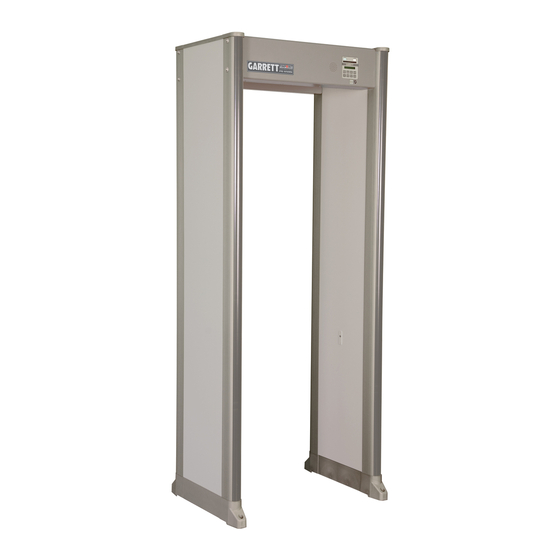
Boasting an enlarged detection field that comprises several horizontal and vertical zones, the Magnascanner PD 6500 can detect weapons within 33 distinct areas of the walk-through. This enlarged detection field increases overall throughput dramatically by revealing the exact locations that need investigation. -
Page 5: Controls, Internal Modules & Alarms Display Panel
Operators should follow the supervisor’s instructions regarding the appropriate response to alarms. Remember that the cause of every alarm must be determined for any detector to be effective in an overall security plan. ©2000 GARRETT METAL DETECTORS, INC. PN 1531100 6/19/00... -
Page 6: Touchpads
(+) and minus (–) touchpads to adjust the volume. 2.2.5. + AND – The plus (+) and minus (–) touchpads are used to change numerical settings, activate certain on/off functions and adjust the volume of the audio alarm. ©2000 GARRETT METAL DETECTORS, INC. PN 1531100 6/19/00... -
Page 7: Pinpoint Lights
Pacing lights located on side panels of the entrance side indicate whether or not a patron may enter the walk-through. The green light indicates walk and the red light indi- cates wait. (See Figure 2-4.) ©2000 GARRETT METAL DETECTORS, INC. PN 1531100 6/19/00... -
Page 8: Internal Modules
DETECTION UNIT (INTERNAL MODULES) Two metal covers protect (from left) the controller module (containing the top circuit board, middle circuit board and the transmitter control board) and the power module. (See Figure 2-5) Figure 2-5 ©2000 GARRETT METAL DETECTORS, INC. PN 1531100 6/19/00... - Page 9 Revert access codes to factory settings (See Section 5.13). 2.5.2. POWER MODULE The power module supplies the power required for operation. Ensure that the power cord is plugged into the connector on the lower left side of the module. PN 1531100 ©2000 GARRETT METAL DETECTORS, INC. 6/19/00...
-
Page 10: Alarms
EVERY ALARM is determined. There are no exceptions. Although no walk-through detector is immune from possible nuisance alarms, if Magnascanner PD 6500 is installed properly, few such alarms should occur. 2.6.2. WARBLE ALARM Occurs when a large metal object, such as a wheelchair, piece of furniture, or metal container, moves through or near the Magnascanner and saturates the detector’s... -
Page 11: Installation Instructions
3.1. SITE SELECTION Before choosing a site for the Magnascanner PD 6500, it is important to consider the volume and throughput of pedestrian traffic, space availability and overall environmen- tal conditions. Position the Magnascanner PD 6500 on a level, stable floor where it remains unaffected by rain, mist or condensation. - Page 12 Step 4 and proceed with the installation adjustments. (See Section 5.) PANELS PANEL A PANEL B DETECTION UNIT FLOOR Styrofoam Packing Insert Figure 3-2 Figure 3-3 CROSSPIECE DETECTION UNIT FLOOR Styrofoam Packing Insert Figure 3-5 Figure 3-4 ©2000 GARRETT METAL DETECTORS, INC. PN 1531100 6/19/00...
-
Page 13: System Information
• AC SYNC or SYNC FAIL • RX A or B ZN # PK FAIL • RX or TX OPTIC FAIL • CABLE MISCONNECT • RX A or B ZN # BAL FAIL ©2000 GARRETT METAL DETECTORS, INC. PN 1531100 6/19/00... - Page 14 Ensure that the cables attached to the top and middle circuit boards are MISCONNECT connected as described in the inside cover of the controller module. Critical failure; PD 6500 cannot operate properly. Correct IMMEDIATELY. ©2000 GARRETT METAL DETECTORS, INC. PN 1531100 6/19/00...
-
Page 15: Installation Adjustments
Each zone adjustment is based on a percentage of the base sensitivity. The top to bottom horizontal zones and their corresponding pinpoint lights are referred to as zones one to six. ©2000 GARRETT METAL DETECTORS, INC. PN 1531100 6/19/00... - Page 16 63% less to 192% greater than the base sensitivity. The installer should consult the supervisor regarding the application requirements of the installation. ©2000 GARRETT METAL DETECTORS, INC. PN 1531100 6/19/00...
- Page 17 (RELAY N/O) or “normally closed” (RELAY N/C) depending on the installation require- ments. Use the + and – touchpads to make a selection. Press ACCESS for next adjustment or OPERATE to resume normal operation. ©2000 GARRETT METAL DETECTORS, INC. PN 1531100 6/19/00...
- Page 18 Press OPERATE to exit the Installation Adjustments mode and resume normal operation. (If ACCESS is pressed, the Installation Adjustments cycle starts over, beginning with the prompt, RX BALANCE.) ©2000 GARRETT METAL DETECTORS, INC. PN 1531100 6/19/00...
-
Page 19: Supervisor Adjustments
Special Note A final decision on program and base sensitivity settings is the sole responsibility of the end user and must be determined by the intent of the security application. ©2000 GARRETT METAL DETECTORS, INC. PN 1531100 6/19/00... - Page 20 Alarm level is an optional tool that helps you determine the lowest level of sensitivity required to activate an alarm for a particular metal object. This information can then be used to determine the desired level of sensitivity. ©2000 GARRETT METAL DETECTORS, INC. PN 1531100 6/19/00...
-
Page 21: Supervisor Responsibilities
Next, select the lowest base sensitivity level at which the smallest forbidden metallic object can be detected. (For helpful tips on selecting base sensitivity, see Section 6.2.) Adjust the zone sensitivity settings as needed. (See Section 5.5.1.) ©2000 GARRETT METAL DETECTORS, INC. PN 1531100 6/19/00... -
Page 22: Operator Responsibilities
LCD and to determine the cause of alarms. The operator should ensure that the: • Magnascanner PD 6500 is always operating properly; • Program and sensitivity settings are accurate by pressing PROGRAM DISPLAY; • LED bar graph shows minimal interference (two lights maximum);... - Page 23 This enables the operator to know from which area(s) objects require removal and to concentrate on the problem areas when hand scanning, resulting in improved overall security and increased throughput. ©2000 GARRETT METAL DETECTORS, INC. PN 1531100 6/19/00...
-
Page 24: Technical Specifications
Operator Responsibilities. Special Note The Magnascanner PD 6500 is a highly-advanced and reliable security metal detector. However, its success ultimately depends on the training and diligence of the men and women who operate it, and the overall security plan of which it is a part. -
Page 25: Traffic Counter
An audible alarm reports any unau- thorized access attempt. 9.13. CONSTRUCTION The PD 6500 is made of attractive scratch- and mar-resistant laminate with resilient end caps, a control panel and heavy-duty aluminum crosspieces. ©2000 GARRETT METAL DETECTORS, INC. PN 1531100 6/19/00... -
Page 26: Regulatory Information
9.14. REGULATORY INFORMATION The Garrett Magnascanner PD 6500 PD meets or exceeds all of the requirements for the 1991 Federal Aviation Administration (FAA) airport applications and specifications, as well as the requirements of the National Institute of Law Enforcement and Criminal Justice (NILECJ) standard # 0601.00, security levels 1–5. -
Page 27: Operating Temperatures
• Passageway interior: Width: 30” (0.76m) Height: 80”(2m) Depth: 23”(0.57m) • Overall Exterior: Width: 35” (0.9m) Height: 87”(2.2m) Depth: 23”(0.57m) • Shipping: Width: 33.5” (232.4cm) Height: 91.5”(15.9cm) Depth: 6.25”(15.9cm) Weight: 149 lbs ©2000 GARRETT METAL DETECTORS, INC. PN 1531100 6/19/00... - Page 28 (e.g., doctor’s orders, etc.), a patron objects to being scanned with a metal detector, it is recommended that an alternative procedure (e.g., manual hand search, non-admit- tance, etc.) be a part of the overall security plan. ©2000 GARRETT METAL DETECTORS, INC. PN 1531100 6/19/00...
-
Page 29: Maintenance & Repair
However, after any component is replaced, the system must be tested thoroughly to confirm that the PD 6500 operates properly. ©2000 GARRETT METAL DETECTORS, INC. PN 1531100 6/19/00... - Page 30 MAGNASCANNER PD 6500 OWNER’S MANUAL CONTROLLER MODULE Figure 10-1 DETECTION UNIT Figure 10-2 ©2000 GARRETT METAL DETECTORS, INC. PN 1531100 6/19/00...
- Page 31 MAGNASCANNER PD 6500 OWNER’S MANUAL Figure 10-3 Figure 10-4 Figure 10-5 ©2000 GARRETT METAL DETECTORS, INC. PN 1531100 6/19/00...
-
Page 32: Replacement Parts
Light Bar Controller Red (Exit) Pcb Ass’y 2338402 Light Bar Slave Set (Exit) Pcb Ass’y 2338502 Light Bar Controller Red/Green (Entrance) Pcb Ass’y 2338412 Hole Plug 9832300 Extrusion Lens 9999200 Cap Panel 9999800 Boot Panel 9999900 ©2000 GARRETT METAL DETECTORS, INC. PN 1531100 6/19/00... -
Page 33: Warranty
OWNER’S MANUAL 10.5. WARRANTY Garrett Electronics, Inc. (“Garrett”) warrants that this Magnascanner PD 6500 Metal Detector is protected by the following limited parts and labor warranty for a period of 24 months (the “Warranty”). During this 24-month period Garrett will inspect and evaluate all security equipment returned to its authorized repair station or factory to determine if the equipment meets Garrett’s performance specifications. -
Page 34: Additional Information
MAGNASCANNER PD 6500 OWNER’S MANUAL ADDITIONAL INFORMATION 11.1. OPERATIONS WORK SHEET Location: Serial Number: Version: Zone Date Seq. Number Prog Base Sens Settings Changes made Initials ©2000 GARRETT METAL DETECTORS, INC. PN 1531100 6/19/00... -
Page 35: Programs
MAGNASCANNER PD 6500 OWNER’S MANUAL 11.2. PROGRAMS The Magnascanner PD 6500 offers several programs designed to help meet specific security needs. Table 11-1 Description/Use(s) PD 6500 General weapons detection programs that Airports provides excellent discrimination against Schools pocket items, such as cigarette packs, coins Courthouse and jewelry. - Page 36 Meets FAA requirements (i.e., three-gun test). Moderate throughput. Figure 11-1 Trends in detection capabili- ties of Loss Prev1 to Loss Prev6. ©2000 GARRETT METAL DETECTORS, INC. PN 1531100 6/19/00...
-
Page 37: Multiple Walk-Through Operation
PD 6500s not plugged into the same AC power line or those with battery back-up option which may be required to operate in the absence of AC power. Setting PD 6500 Controller Board Figure 11-2 PN 1531100 ©2000 GARRETT METAL DETECTORS, INC. 6/19/00... -
Page 38: Ac & Dc Control
Figure 11-4. The optically-isolated triac output con- ducts only when the red ALARM light is illuminated. Control should not exceed 48Vrms and 100mA. The output is electrically isolated from ground. CONTROLLER CIRCUIT BOARD Figure 11-4 PN 1531100 ©2000 GARRETT METAL DETECTORS, INC. 6/19/00... -
Page 39: Battery Pack Module (Optional)
6. Disconnect the power supply module connector from the controller circuit board. (See Figure 11-8.) 7. Reconnect the power supply and battery pack modules. (See Figure 11-9.) 8. Reassemble the system and test. ©2000 GARRETT METAL DETECTORS, INC. PN 1531100 6/19/00... -
Page 40: Electrical Wiring
Green to ground Black to line hot White to line neutral MAGNASCANNER PD 6500 #1167720 (INTERNATIONAL) Includes a European power cord. To replace or remove plug, or to hard wire to an AC junction box, use: Green/Yellow to ground Brown... - Page 41 Garrett PD 6500 Examples of Pinpoint Detection The above graphic shows examples of how pinpoint detection is indicated on the PD 6500. A knife located on the center of a persons body activates pinpoint lights on BOTH sides of the archway. A weapon located either on the right or left side of the body activates pinpoint lights on the right OR left side of the archway respectively.
- Page 42 Copyright ©2001 Garrett Metal Detectors. All rights reserved PN 1531100/0600...