Table of Contents
Advertisement
USER MANUAL
Model 11674xx
USA
Garrett Metal Detectors
Security Division
1881 W. State Street
Garland, Texas 75042-6797 USA
Phone:
1.800.234.6151
Fax:
1.972.494.1881
Email:
security@garrett.com
Website:
garrett.com
International
Garrett Metal Detectors
International Security Division
1881 W. State Street
Garland, Texas 75042-6797 USA
Phone:
1.972.494.6151
Fax:
1.972.494.1881
Email:
international@garrett.com
Website:
garrett.com
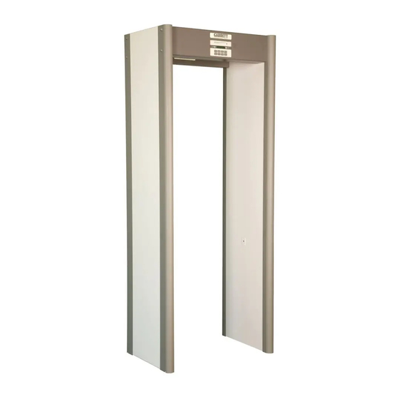
CS 5000
™
Advertisement
Table of Contents

Related Manuals for Garrett CS 5000


Summary of Contents for Garrett CS 5000
-
Page 1: User Manual
USER MANUAL CS 5000 ™ Model 11674xx Garrett Metal Detectors Security Division 1881 W. State Street Garland, Texas 75042-6797 USA Phone: 1.800.234.6151 Fax: 1.972.494.1881 Email: security@garrett.com Website: garrett.com International Garrett Metal Detectors International Security Division 1881 W. State Street Garland, Texas 75042-6797 USA Phone: 1.972.494.6151... - Page 3 Maximum Altitude: 3000 meters CAUTION! CS 5000 must be firmly anchored to the floor to reduce the risk of injury to persons or property damage due to accidental knock down. Warning! Battery Safety: The optional Battery Backup Module and the CMA Interface module contain recharge- able batteries that may contain small amounts of harmful substances.
- Page 4 User Manual MEDICAL SAFETY Garrett Metal Detectors makes every effort to ensure its products are safe for use. Extensive research by Garrett has produced no information which would indicate that its products have any adverse effects on medical implants, pregnancy, recording media or magnetic strips. Garrett makes every effort to cooperate with medical device manufacturers and to communicate with agencies such as the United States Food and Drug Administration and Health Canada as a means of assuring product safety.
-
Page 5: Table Of Contents
MULTIPLE UNIT OPERATION ................38 11.4 AC & DC CONTROL ................... 39 11.5 REMOTE CONSOLES ..................40 11.6 BATTERY BACK-UP MODULE ................41 11.7 STABILIZER BASE ..................... 42 11.8 ELECTRICAL WIRING ..................43 ©2009 GARRETT METAL DETECTORS PN 1530100 REV H... -
Page 6: General Description
Two levels of codes eliminate the need for bothersome keys for locked doors or other protective devices, while the CS 5000 circuitry provides precise accuracy of calibration. Access Code #1 is used by supervisors for selecting programs and sensitivity with Access Code #2 designed for initial set up and overall control. -
Page 7: Controls & Modules
Program and Sensitivity levels that have been selected. Operators should be instructed to respond to all alarms. For any detector to be effective in a security system it is absolutely necessary that the cause of EVERY ALARM be determined. ©2009 GARRETT METAL DETECTORS PN 1530100 REV H... -
Page 8: Touchpads
2.2.2 OPERATE Whenever this touchpad is pressed, the CS 5000 activates all circuits, initiates a self-diagnosis pro- gram and places the unit in the Operate Mode within fifteen (15) seconds. This diagnostic program for instant fault detection can be activated at any time by touching this OPERATE pad. If any faults are ever found, they will be immediately reported on the LCD display. -
Page 9: Internal Modules
This module contains all circuitry that relates to the power required for operation of the detector. The Power Cord should be plugged into the Power Supply Module at the connector on the lower left side. ©2009 GARRETT METAL DETECTORS PN 1530100 REV H... - Page 10 This switch need be placed in the OFF position only during storage or when the unit is not being used and is not connected to AC power for more than 24 hours. See Section 11.6.1 for installation instructions. © 2009 GARRETT METAL DETECTORS PN 1530100 REV H...
-
Page 11: Installation Instructions
INSTALLATION INSTRUCTIONS SITE SELECTION The Garrett CS 5000 should be located on a level, stable floor with no large metal items within three (3) feet. Any nearby large metallic object can interfere with operation of the detector. Moving metallic objects, such as an escalator or revolving door, close to the detector can cause false alarms. Such alarms can also be caused by electrical interference from radio telephones, television monitors, power- ful electronic motors and transformers, power cables and control circuits. - Page 12 Open door of the Detection Unit and, first, connect Power Cord. Then, connect Cable A and Cable B to the Panels as shown. PANEL A PANEL B CABLE A CABLE B POWER CORD OR CORD SET © 2009 GARRETT METAL DETECTORS PN 1530100 REV H...
- Page 13 Detection Unit and Overhead Crosspiece to the Side Panels and adjust as necessary. 3.3.9 Connect to the power line, and proceed with Installation Adjustments (See Section 5.) ©2009 GARRETT METAL DETECTORS PN 1530100 REV H...
-
Page 14: Self-Diagnostic Tests
CS 5000 User Manual SELF-DIAGNOSTIC TESTS The Garrett CS 5000 LCD panel provides valuable information concerning the operation of this unit and the self-diagnostic program of which it is capable. OPERATING INFORMATION When the unit is placed into operation from the Standby Mode, the following information is reported: 1. - Page 15 If this sound is heard, the operator should see that the problem object is moved away, and the person being inspected should be required to pass through the archway again after the green READY light appears. ©2009 GARRETT METAL DETECTORS PN 1530100 REV H...
-
Page 16: Installation Adjustments
The Installation Adjustment Mode, which can be accessed only through use of a four-digit code (Access Code #2), permits the CS 5000 to be set up properly for best performance in a given opera- tional environment. Various options permit setting the unit for proper operation in conjunction with other walk-through units or for dealing with typical operation problems. - Page 17 • With power connected and the unit in its Operate Mode press the Access Code Reset button in the upper center of the circuit board. • ACCESS CODE #1 will again be 1234 and ACCESS CODE #2 will be 5678. ©2009 GARRETT METAL DETECTORS PN 1530100 REV H...
-
Page 18: Supervisor Adjustments
The + or - touchpad is used to turn the IR Analysis off and on. Whenever this is done, it is necessary to press ACCESS for the next adjustment or OPERATE to return to normal operation. Utilization of the Infrared Sensor is not required for operation of the CS 5000 and may be disabled if desired. - Page 19 4. The IR Analysis enables the detector to count the number of individuals passing through it. ALARM LEVEL READING Computerized circuitry of the Garrett CS 5000 permits the unit to report the minimum sensitivity level required to cause an alarm for the particular metallic target that is being passed through the archway.
-
Page 20: Supervisor Responsibilities
NOTE: Types of Audio Alarms Understanding the audio alarms the CS 5000 can sound will enable both supervisors and operators to understand the detector better and help assure totally accurate screening. Each of three unique audio alarms is designed to call the operator’s attention to current circumstances:... - Page 21 “clean” of extraneous metallic items. ANKLE BOOST The CS 5000 (Version 2.60 or greater, as displayed in Self-Test, Page 10) incorporates the ability to adjust the sensitivity at ankle level without increasing sensitivity throughout the passageway. The fac- tory setting is with standard ankle boost to allow easier passage of shoes containing metal shanks.
-
Page 22: Technical Specifications
8.10 REGULATORY STANDARDS The Garrett CS 5000 programs have been designed specifically to meet (or exceed) all 1991 Federal Aviation Administration airport applications specifications as well as all requirements of National Institute of Law Enforcement and Criminal Justice (NILECJ) standard 0601.00, security levels 1-5. - Page 23 Width: 35” (0.9m) / Height: 87” (2.2m) / Depth: 23” (0.57m) • Shipping: Width: 33.5” (85.1cm) / Height: 91.5” (223.4cm) / Depth: 6.25” (15.9cm) / Weight: 129 lbs. (58.6 kg) • Throughput Rate: Not limited by electronics; 50-60 detections/minute is reasonable. • Optional features: Remote operating capability (indicators and/or console); battery back-up module (built-in for portability); Magnadolly (for easy movement of assembled unit). ©2009 GARRETT METAL DETECTORS PN 1530100 REV H...
-
Page 24: Maintenance & Repair
It is necessary to test the system carefully to verify operation and the suitability of the product after any component replacement. © 2009 GARRETT METAL DETECTORS PN 1530100 REV H... - Page 25 User Manual POWER SUPPLY & BATTERY BACK-UP CONNECTORS ACCESS CODE RESET FRONT TOUCHPAD CONNECTOR (BOTTOM OF PC BOARD) RIBBON CABLE CONNECTOR (BOTTOM OF PC BOARD CONNECTOR) CABLE B CONNECTOR CABLE A CONNECTOR ©2009 GARRETT METAL DETECTORS PN 1530100 REV H...
- Page 26 CS 5000 User Manual © 2009 GARRETT METAL DETECTORS PN 1530100 REV H...
-
Page 27: Replacement Parts
Ribbon Cable-16 conductor, 6” 9504700 Screw 1/4-20x3” 9820400 Finishing Washer 9820500 Screw 4-40-3/8 flat head, light beige 9822980 Crosspiece 9968800 Cover with window 9969570 Controller Cover 9984500 Cord - 10' Jumper 9424900 ©2009 GARRETT METAL DETECTORS PN 1530100 REV H... -
Page 28: Warranty
CS 5000 User Manual WARRANTY Garrett Electronics, Inc. (“Garrett”) warrants that this CS 5000 weapons/metal detector is pro- tected by the following limited parts and labor warranty for a period of 24 (twenty-four) months (the “Warranty”). During this 24-month period Garrett will inspect and evaluate all security equipment returned to its authorized repair station or factory to determine if the equipment meets performance specifications. -
Page 29: Operating Instructions
5000 walk-through metal detector. It contains four sections: • Description of the detector; • Description of all controls; • Operators’ responsibilities; • Basic operating instructions. 10.1 BASIC INSTRUCTIONS In addition to following all operating procedures as directed by supervisors the operator of a CS 5000 detector has only these responsibilities: • Assure that the detector is always operating properly; • Select Off and Operate / On modes; • Regulate volume of the alarm; • Read and/or reset the counter; • Respond to all alarms. - Page 30 It is absolutely necessary that the cause of EVERY ALARM be determined. 10.6 TYPES OF AUDIO ALARMS The CS 5000 has three types of alarms. Each of these unique alarms is designed to call the operator’s attention to current circumstances: 10.6.1 SET-UP ALARM Produces two short beeps as a person is walking through the unit.
- Page 31 10.8.3 COUNTER Since the current traffic count of the CS 5000 is usually displayed, this touchpad will be needed only for resetting the counter. Pressing and holding this touchpad for ten (10) seconds causes the counter to return to zero (0). Whenever the LCD displays information other than the current traffic count, pressing this touchpad will cause the count to appear.
- Page 32 10.12 READY LIGHT The green READY light, located at the top center of the Control Panel indicates that the CS 5000 is operating. When the green light is showing, power has been turned on and the unit is prepared to detect metal.
- Page 33 It is important to remember that after power has been turned on, the CS 5000 is operating at all times. Its IR Sensor capability inhibits the alarm only when there is no object or person within the archway.
- Page 34 The CS 5000 is a fine walk-through metal detector. But, in the end, even an electronic device as sophisticated as this is only a tool. Ultimate success of its operation is dependent upon: • The training and diligence of the men and women who operate it;...
-
Page 35: Additional Information
_____ _______________________________ _______ _________ __________ _____ _____ _______________________________ _______ _________ __________ _____ _____ _______________________________ _______ _________ __________ _____ _____ _______________________________ _______ _________ __________ _____ _____ _______________________________ _______ _________ __________ _____ _____ _______________________________ _______ ©2009 GARRETT METAL DETECTORS PN 1530100 REV H... -
Page 36: Programs
• Programs 14 and 15 provide a balanced response to ferrous and conductive objects. • Immunity to external noise is poor, making these programs difficult to use in noisy environments. • Overall discrimination is moderate. • Recommended applications include loss prevention and installations where specific objects need to be emphasized or ignored. 11.2.3 PROGRAM A • Custom program designed to detect the broadest range of objects. • Emphasis of detection is on conductive objects. This program provides the highest level of security available in the CS 5000. • Immunity to external noise is moderate, making this program usable in most environments. • Discrimination is poor. • Recommended applications include prisons and other installations where volume requirements allow thorough inspection of each individual. 11.2.4 PROGRAM B • Custom program designed to detect ferrous and conductive objects equally. • Immunity to external noise is moderate, making this program usable in most environments. • Discrimination is moderate. - Page 37 Maximum security screening prevention, law enforcement non-ferrous (Low throughput) Alternative when A, C, D cannot be used due to FAA 3 gun, ferrous, Mild All applications extreme environmental non-ferrous Low Throughput conditions ©2009 GARRETT METAL DETECTORS PN 1530100 REV H...
-
Page 38: Multiple Unit Operation
Repeat pattern of CHANNELS A,C, and D for any additional units. 11.3.3 CASE III: Description: • Three (3) or more units that interfere with each other; • Units not plugged into the same power line or units with battery back-up option which may be required to operate in the absence of AC power. • With the exception of the first and last units, the SH-3 jumper must be removed. This jumper is located on the Controller Board Assembly. Refer to the drawing for exact location. © 2009 GARRETT METAL DETECTORS PN 1530100 REV H... -
Page 39: Ac & Dc Control
The output is an open collector configuration capable of switching 15V at 100mA or less, which includes connections to computing devices and other equipment requiring low level DC. ©2009 GARRETT METAL DETECTORS PN 1530100 REV H... -
Page 40: Remote Consoles
A complete remote console with all control functions that are available on the overhead panel is avail- able for monitoring and controlling functions of the Magnascanner CS 5000 from a location apart from the archway. This remote console is connected to the overhead... -
Page 41: Battery Back-Up Module
This optional module is a field-installable assembly that provides power to operate the Magnascanner CS 5000 for up to twenty (20) hours on a fully charged battery. System software includes an alarm feature that alerts the operator to a low-battery condition. This ensures that the unit continues to operate at its peak performance level. -
Page 42: Stabilizer Base
DO NOT PINCH the cord between the panel and the plate. Ensure that the head of the screw is tight against the plate to prevent the panels from sliding. 11.7.5 Assemble the unit. 11.7.6 Place unit in upright position at selected operating location. © 2009 GARRETT METAL DETECTORS PN 1530100 REV H... -
Page 43: Electrical Wiring
Comes with a European power cord. If the plug must be replaced or removed to hardwire to an AC junction box, use the following wiring list: Green/Yellow To Ground Brown To Line Hot Blue To Line Neutral ©2009 GARRETT METAL DETECTORS PN 1530100 REV H...