Table of Contents
Advertisement
Safe Operation Practices • Set-Up • Operation • Maintenance • Service • Troubleshooting • Warranty
O
'
M
peratOr
s
anual
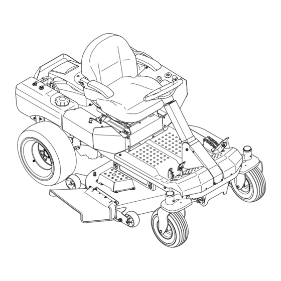
Z-Force S60 & Z-Force S48 Commercial
WARNING
READ AND FOLLOW ALL SAFETY RULES AND INSTRUCTIONS IN THIS MANUAL
BEFORE ATTEMPTING TO OPERATE THIS MACHINE.
FAILURE TO COMPLY WITH THESE INSTRUCTIONS MAY RESULT IN PERSONAL INJURY.
CUB CADET LLC, P.O. BOX 361131 CLEVELAND, OHIO 44136-0019
Printed In USA
Form No. 769-08661
(November 12, 2012)
Advertisement
Table of Contents

Related Manuals for Cub Cadet Z-Force S Commercial 48


Summary of Contents for Cub Cadet Z-Force S Commercial 48
- Page 1 READ AND FOLLOW ALL SAFETY RULES AND INSTRUCTIONS IN THIS MANUAL BEFORE ATTEMPTING TO OPERATE THIS MACHINE. FAILURE TO COMPLY WITH THESE INSTRUCTIONS MAY RESULT IN PERSONAL INJURY. CUB CADET LLC, P.O. BOX 361131 CLEVELAND, OHIO 44136-0019 Printed In USA Form No. 769-08661...
-
Page 2: Table Of Contents
Visit us on the web at www.cubcadet.com See How-to Maintenance and Parts Installation Videos at www.cubcadet.com/tutorials ◊ Locate your nearest Cub Cadet Dealer at (877) 282-8684 ◊ Write to Cub Cadet LLC • P.O. Box 361131 • Cleveland, OH • 44136-0019... -
Page 3: Safe Operation Practices
Important Safe Operation Practices WARNING! This symbol points out important safety instructions which, if not followed, could endanger the personal safety and/or property of yourself and others. Read and follow all instructions in this manual before attempting to operate this machine. Failure to comply with these instructions may result in personal injury. - Page 4 A missing or damaged discharge cover can cause blade If situations occur which are not covered in this manual, use contact or thrown object injuries. care and good judgment. Contact your customer service representative for assistance. Stop the blade(s) when crossing gravel drives, walks, or roads and while not cutting grass.
- Page 5 Children • The fore/aft single-locking adjustment tracks operate on roller-bearings for smooth and almost effortless operation. Tragic accidents can occur if the operator is not alert to the The lever for seat track actuation is near the right front presence of children. Children are often attracted to the corner of the seat bottom, and allows fore/aft adjustment machine and the mowing activity.
-
Page 6: Spark Arrestor
General Service Do not change the engine governor settings or over-speed the engine. The governor controls the maximum safe Never run an engine indoors or in a poorly ventilated area. operating speed of the engine. Engine exhaust contains carbon monoxide, an odorless, Maintain or replace safety and instruction labels, as and deadly gas. -
Page 7: Safety Symbols
Safety Symbols This page depicts and describes safety symbols that may appear on this product. Read, understand, and follow all instructions on the machine before attempting to assemble and operate. Symbol Description READ THE OPERATOR’S MANUAL(S) Read, understand, and follow all instructions in the manual(s) before attempting to assemble and operate WARNING—... - Page 8 2 — S ection peration racticeS...
-
Page 9: Assembly & Set-Up
Assembly & Set-Up Contents of Crate • One Deck Wash Hose Coupler • One Lawn Tractor • One Oil Drain Hose • One Z-Force S Operator’s Manual • One Engine Operator’s Manual Tractor Preparation Steering Wheel Remove the hardware for attaching the steering wheel Remove the upper crating material from the shipping pallet, from beneath the steering wheel cap. - Page 10 Adjusting the Seat Remove the two shoulder bolts and lock nuts in the seat pan as shown in Figure 3-3. To adjust the position of the seat, push the seat adjustment lever to the left. Slide the seat forward or rearward to the desired position;...
- Page 11 Connecting the Battery Cables Install the hitch bracket and muffler mount bracket as shown in Figure 3-7 and secure with the hex flange screws CALIFORNIA PROPOSITION 65 WARNING and flange lock nuts removed in step 1. Battery posts, terminals, and related accessories contain lead and lead compounds, chemicals known to the State of California to cause cancer and reproductive harm.
-
Page 12: Controls & Features
Controls & Features Cup Holder Ignition Switch Hour Meter/ Indicator Panel Fuel Tank Cap Parking Break PTO Switch Engagement Lever Choke Control Index Plate Deck Lift Pedal Throttle Control Seat Adjustment Lever Drive Pedal Reverse Pedal Ignition Switch NOTE: References to LEFT, RIGHT, FRONT, and REAR indicate that position on the tractor when facing forward while seated in the The ignition switch is located on the LH console operator’s seat. -
Page 13: Throttle Control
If this indicator and display come on during downward to disengage the clutch. operation, check the battery and charging system for possible causes and/or contact your Cub Cadet dealer. The PTO switch must be in the “disengaged” position when starting the engine. -
Page 14: Choke Control
Choke Control Transmission Oil Expansion Reservoir (Not Shown) The choke knob controls the position of the The transmission oil expansion reservoir is connected by hoses engine choke and is located on the RH console. to the RH and LH transmission assemblies, and is located behind CHOKE Pull the knob out to choke the engine;... -
Page 15: Operation
This tractor is equipped with a safety interlock system for the extreme caution if the surface is slippery. protection of the operator. If the interlock system should ever malfunction, do not operate the tractor. Contact your Cub Cadet • Slow down before turning and come to a complete stop dealer. -
Page 16: Starting The Engine
Engaging the PTO Operator must be sitting in the tractor seat. Engage the parking brake. Refer to Figure 5-2. Engaging the PTO transfers power to the cutting deck or other (separately available) attachments. To engage the PTO: Move the throttle control lever to the FAST position. -
Page 17: Driving The Tractor
Driving The Tractor Allow the engine to run for a few minutes at mid-throttle before putting the engine under load. WARNING! Avoid sudden starts, excessive speed Observe the hour meter/indicator panel. If the battery and sudden stops. indicator light or oil pressure light come on, immediately stop the engine. - Page 18 Driving On Slopes Refer to the SLOPE GAUGE on page 8 to help determine slopes where you may operate the tractor safely. WARNING! Do not mow on inclines with a slope in excess of 15 degrees (a rise of approximately 2-1⁄2 feet every 10 feet).
-
Page 19: Maintenance & Adjustment
Recharge the battery before returning to service. Although be performed by any engine repair establishment or individual. the tractor may start, the engine charging system may not Warranty repairs must be performed by a Cub Cadet Dealer. fully recharge the battery. Battery... - Page 20 Using a fuel stabilizer such as STA-BIL® for storage Pivot the operator’s seat forward and clean the reservoir between 30 and 90 days: cap and the area around the cap to prevent debris from contaminating the transmission oil. See Figure 6-1. •...
- Page 21 Lubrication Attach the hose coupler to the water port on your decks surface. See Figure 6-2. WARNING! Before lubricating, repairing, or inspecting, always disengage PTO, set parking brake, stop engine and remove key to prevent unintended starting. Nozzle Adapter Front Wheels Deck Wash Nozzle Each of the front wheel spindles and rims is equipped with a grease Adapter Lock Collar...
- Page 22 Adjustments Deck Spindle Grease fittings can be found on top of each spindle bolt. See NOTE: Check the tractor’s tire pressure before performing Figure 6-4 for the Z-Force S60 and Figure 6-5 for the Z-Force any deck leveling adjustments. Refer to Tires on page 22 for S48.
- Page 23 Leveling the Deck (Front To Rear) Setting the Deck Wheels NOTE: Check the tractor’s tire pressure before performing Move the tractor on a firm and level surface, preferably any deck leveling adjustments. Refer to Tires on page 22 for pavement, and proceed as follows information regarding tire pressure.
- Page 24 Rear Deck Rollers The rear deck rollers can be placed in two positions. To change the height of the rear deck rollers Refer to Figure 6-9 and proceed as follows: Lower Hex Upper Hex Screw Screw Upper Flange Lock Nut Figure 6-9 Loosen —...
-
Page 25: Service
If you have a recurring problem with blown fuses, have the tractor’s electrical system checked by your Cub Cadet Service Dealer. Relays and Switches There are several safety switches in the electrical system. If a... -
Page 26: Deck Removal
Deck Removal Idler Pulley Remove the mower deck from the tractor as follows: Bracket Move the tractor to a level surface, disengage the PTO, stop the engine, and set the parking brake. Remove the lock rod by pressing the pedal forward to release tension then rotate the lock rod until the end of the rod points upward and slide it out of the deck height bracket. -
Page 27: Deck Installation
Deck Installation After all four cotter pins are secure, slide the deck forward and hook the deck to the U-rod. Install the deck on the tractor as follows: Route the belt as shown in Figure 7-9 for Z-Force S60 and Place the deck lift pedal in the highest mowing position and Figure 7-10 for the Z-Force S48. -
Page 28: Replacing The Belt
Replacing the Belt Mower Blade Care Remove the deck from beneath the tractor, (refer to Deck WARNING! Protect your hands by using heavy Removal on page 26). gloves when handling the blades. When servicing the mower deck, be careful not to cut yourself on Pull the four draw latches up and away from the deck the sharpened blades. - Page 29 Changing the Transmission Drive Belt Several components must be removed and special tools used in order to change the tractor’s transmission drive belt. See your Cub Cadet dealer to have the transmission drive belt replaced. 7 — S ection ervice...
-
Page 30: Troubleshooting
Troubleshooting Problem Cause Remedy Excessive vibration 1. Cutting blade loose or unbalanced. 1. Tighten blade and spindle. 2. Damaged or bent cutting blade. 2. Replace blade. Uneven cut 1. Deck not leveled properly. 1. Perform side-to-side deck adjustment. 2. Dull blade. 2. -
Page 31: Replacement Parts
Replacement Parts Component Part Number and Description 01005376 Deck Belt (Z-Force S60) 954-04262 PTO Belt (Z-Force S60) 954-3092A Drive Belt 954-04044A Deck Belt (Z-Force S48) 942-04415 Mowing Blade (Z-Force S60) 942-04417 Mowing Blade (Z-Force S48) 918-3129C Deck Spindle 634-3159 Deck Wheel (Z-Force S60) 734-04155 Deck Wheel (Z-Force S48) 925-1707D... - Page 32 Component Part Number and Description 946-1086 Throttle Control Cable 946-04752 Choke Control Cable 925-2054A Ignition Key 01006693P Chute Deflector 634-04698 Wheel Assembly 634-04623 Caster Wheel Assembly 9 — R ection eplacement aRtS...
-
Page 33: Attachments & Accessories
Attachments & Accessories Part No. Part 19A70011100 * 48” Triple Bagger 19A70012100 * 60” Triple Bagger 59A30034150 Twin Bagger, Power Assist 59A30034150 Power Assist Twin Bagger 19A70018100 Headlight Kit 19A70016100 Mulch Kit (Z-Force S48) 19A70017100 Mulch Kit (Z-Force S460 19A70024100 58”... -
Page 34: Warranties
FEDERAL and/or CALIFORNIA EMISSION CONTROL WARRANTY STATEMENT YOUR WARRANTY RIGHTS AND OBLIGATIONS MTD Consumer Group Inc, the United States Environmental Protection Agency (EPA), and, for those products certified for sale in the state of California, the California Air Resources Board (CARB) are pleased to explain the emission (evaporative and/or exhaust) control system (ECS) warranty on your outdoor 2006 and later small off-road spark-ignited engine and equipment (outdoor equipment engine) In California, new outdoor equipment engines must be designed, built and equipped to meet the State’s stringent anti-smog standards (in other states, 1997 and later model year equipment must be designed, built, and equipped to meet the U.S. - Page 35 Add-on or modified parts that are not exempted by the Air Resources Board may not be used. The use of any non-exempted add-on or modified parts by the ultimate purchaser will be grounds for disallowing a warranty claims. MTD Consumer Group Inc will not be liable to warrant failures of warranted parts caused by the use of a non-exempted add-on or modified part.
- Page 36 Without limiting the foregoing, this limited warranty does not provide coverage in the following cases: The limited warranty set forth below is given by Cub Cadet LLC with respect to new merchandise purchased or leased and used in the a. Routine maintenance items such as lubricants, filters, blade...