Husqvarna 850 Operator's Manual
Husqvarna zero turn riding mower operator's manual
Hide thumbs
Also See for 850:
- Operator's manual (40 pages) ,
- Operator's manual (13 pages) ,
- Operator's manual (40 pages)

Related Manuals for Husqvarna 850


Summary of Contents for Husqvarna 850
- Page 1 Rider 850/970 Operator´s manual Please read these instructions carefully and make sure you understand them before using the machine. 101 89 35-26...
-
Page 3: Table Of Contents
CONTENTS Operator’s Manual for Rider 850 Rider 970 Dismantling of the machine hoods ... 20 Checking the engine’s oil level ... 21 Checking the engine’s cooling air intake ... 21 Checking the fuel pump’s air filter ... 21 Checking and adjustment of steering wires ... -
Page 4: Safety Instructions
SAFETY INSTRUCTIONS 1. Safety rules, USA nomenclature Safe operation practices for ride-on mowers IMPORTANT! This cutting machine is capable of amputating hands and feet and throwing objects. Failure to ob- serve the following safety instructions could result in serious injury or death. General operation 1. - Page 5 SAFETY INSTRUCTIONS IV. Service 1. Use extra care in handling gasoline and other fuels. They are flammable and vapours are explosive. a) Use only an approved container. b) Never remove gas cap or add fuel with the engine running. Allow engine to cool before refuelling.
-
Page 6: Explanation Of Symbols
EXPLANATION OF SYMBOLS These symbols are on the machine and in the operator´s manual. Study them carefully so that you know what they mean. Reverse Neutral Fast Oil pressure Cutting height Use eye and hearing protection Clutch in Sound level Warning! Rotating blades Never use the machine if persons, especially children, or animals, are in the vicinity... -
Page 7: Safety Instructions
SAFETY INSTRUCTIONS These instructions are for your safety. Read them carefully. This symbol implies that important safety rules are applicable. This is for your safety and the operating reliability of the machine. General use: • Make yourself familiar with the controls and how to stop quickly. -
Page 8: Driving On Slopes
SAFETY INSTRUCTIONS • Watch out for traffic when working close to a road, or crossing one. • Be careful when rounding a fixed object so that the blades do not hit it. Never drive intentionally over a foreign object. • The machine is heavy and can cause very severe crush injuries. -
Page 9: Children
SAFETY INSTRUCTIONS • Do not cut close to edges, ditches or banks. The machine can suddenly tip over if a wheel goes over the edge of a drop or a ditch, or if a bank gives way. • Do not cut wet grass. It is slippery and the tyres can loose their grip so that the machine slides. - Page 10 SAFETY INSTRUCTIONS • Avoid overfilling. If fuel has been spilt on the machine wipe it up and wait until it has evapor- ated before starting the engine. If fuel is spilt on clothes, change them. • Be extra careful when handling battery acid. Spilling acid on the skin can cause severe burn injuries.
-
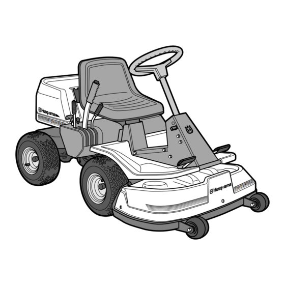
Page 11: Presentation
Both models are fitted with engines from Briggs & Stratton of 10.5, 12.5 and 15.5 hp. Rider 850 has a cutting unit which throws out the grass at the rear and a cutting width of 850 mm. Location of the controls 1. Ignition lock 2. -
Page 12: Throttle/Choke Lever
PRESENTATION Throttle and Choke lever The engine speed is adjusted with the throttle control, and thereby also the rotation speed of the blades. The control is also used to activate the choke function. When the choke is used the engine receives a richer mixture of fuel and air, which simplifies cold start. -
Page 13: Parking Brake
When engaging reverse gear the lock button on the gear shift must be pressed. Cutting unit Rider 850 has a cutting unit with rear ejection, i.e. the grass cuttings are thrown out behind the cutting unit. Rider 970 can be delivered with a cutting unit which has rear or side ejection. -
Page 14: Lift Lever For Cutting Unit
Lift lever for cutting unit The lift lever is used to set the cutting unit in trans- port or cutting position. If the lever is pulled back the unit will lift up and the blades stop rotating (transport position). If the lock button is pressed and the lever is moved forward the unit will lower down and the blades begin rotating (cutting position). -
Page 15: Seat
Seat The seat has a jointed attachment on the front edge and can be tipped forward. The seat can also be adjusted lengthways. Release the wheels under the seat and adjust it forwards or backwards to the required position. Lock the adjustment with the wheels. Fuelling The engine should be run on at least 92 octane leaded or unleaded petrol/gasoline (not oil mixed). -
Page 16: Driving
Before starting • Read the safety instructions and information on the location and function of the controls before starting (see pages 5–13). • Conduct daily maintenance before starting (see maintenance schedule on page 19). Adjust the seat to the required position. Starting the engine 1. - Page 17 Cold engine: 4. Push the throttle control to position 3 (choke position). In this position the engine receives a richer mixture so that the engine starts more easily. Warm engine: 5. Set the throttle control midway between position 1 and 2. 6.
-
Page 18: Driving The Machine
Driving the machine 1. Release the parking brake by pressing the brake pedal. 2. Press the clutch and engage the required gear. The gearbox has five forward drive positions, neutral, and reverse. To engage reverse gear the lock button must be pressed down. •... -
Page 19: Cutting Tips
3. Select the required cutting height (1–9) with the cutting height lever. To obtain a uniform cutting height it is important that the tyre pressures are equal on both front wheels (60 kPa). 4. Push in the lock button on the lift lever and lower down the cutting unit. -
Page 20: Starting On Slopes
Starting on slopes 1. Apply the parking brake. 2. Push the throttle control to 3/4 position to full throttle position. 3. Push down the clutch and engage first gear. 4. Carefully release the clutch. 5. When the engine begins to drive, release the parking brake. -
Page 21: Maintenance
The following is a list of the maintenance which should be conducted on the machine. For the items which are not described in these instructions go to an authorised service workshop. Maintenance Check the engine’s oil level Check the engine’s cooling air inlet Check the fuel pump’s air filter Check the steering wires Check the brakes... -
Page 22: Dismantling Of The Machine Hoods
MAINTENANCE Dismantling of the machine hoods Engine hood The engine is accessible for servicing when the engine hood is lifted up. Tilt the seat forward, release the rubber strap under the seat, and tilt the hood backwards. Front hood Release the screws in the front hood (3) and lift off the hood. -
Page 23: Checking The Engine's Oil Level
Check the engine’s oil level Check the oil level in the engine when the machine is horizontal. Dismantle the engine hood as per the description on page 20. Release the dip stick and pull out. Wipe off the oil and insert again. The dip stick must be fully screwed down. -
Page 24: Checking And Adjustment Of Steering Wires
Checking and adjustment of the steering wires The steering is controlled by means of wires. These can in time become slack, which implies that the adjustment of the steering becomes altered. Check and adjust the steering as follows: 1. Dismantle the frame-plate by releasing the screws (two on each side). -
Page 25: Checking The Brake
Checking the brake The brake is of the disc brake type and is fitted on the gearbox. Check that the brake is correctly adjusted by meas- uring the distance between the brake lever and the front edge of the recess on the chassis. The distance should be 0–1 mm when the brake is not applied. -
Page 26: Replacement Of Air Filter
Replacing the air filter If the engine seems to lack power or goes irregu- larly the reason may be that the air filter is clogged. It is therefore important to replace the air filter at regular intervals (see maintenance schedule on page 19 for correct service interval). -
Page 27: Checking And Adjustment Of Cutting Unit's Ground Pressure Rider 970
Checking and adjustment of the cutting unit’s ground pressure Rider 970 To achieve the best cutting results the cutting unit should follow the underlying surface without press- ing too hard against it. The pressure is adjusted with a screw on each side of the machine. -
Page 28: Adjusting The Parallelism Of The Cutting Unit
Adjustment of the cutting unit’s parallelism Adjustment of Rider 850 1. Dismantle the front hood and right-hand fender as described on page 20. 2. Vertical adjustment of the cutting unit is made with the adjusting nuts on the back edge of the lift-strut. -
Page 29: Dismantling The Cutting Unit
The cutting unit can be released from the machine for cleaning or checking of the blades and screws. Dismantle the cutting unit on Rider 850 as follows: 1. Dismantle the front hood and right-hand and left- hand fenders as described on page 20. -
Page 30: Checking The Blades
IMPORTANT INFORMATION Replacing or sharpening the blades should be conducted by an authorised service workshop. Cutting unit on Rider 850 (rear ejection) Checking the tyre pressure The tyre pressure should be 60 kPa (0.6 kp/cm round. To improve driving the pressure on the rear tyres can be reduced to 40 kPa (0.4 kp/cm... -
Page 31: Changing The Oil
1.2 litres. 6. Run the engine warm and then check that there is no leakage from the drain plug. Lubrication (850) All joints and bearings are lubricated on manufac- ture with molybdenum sulphide grease. Re-grease with same type of grease. -
Page 32: Checking And Adjustment Of Throttle Wire
Checking and adjustment of the throttle wire If the engine does not respond as it should do when the throttle lever is moved or if the top speed is not reached, the throttle wire may need adjust- ing. 1. Release the clamping screw (see arrow) and push the throttle control to full throttle position. -
Page 33: Trouble Shooting Schedule
TROUBLE SHOOTING SCHEDULE Problem Engine will not start. Starter does not pull round engine. Engine does not run smoothly. Engine seems to have no power. Engine overheats. Battery does not charge. Machine vibrates. Uneven mowing. Procedure • Fuel tank empty. •... -
Page 34: Storage
Winter storage At the end of the season the machine should immediately be put in order for storage, also if it is going to stand idle for more than 30 days. Fuel which is left to stand for long periods (30 days or more) can leave tacky deposits which can block the carburettor and interfere with the engine. -
Page 35: Technical Data
Tyre pressure, front & rear 60 kPa (0.6 kp/cm Max. gradient 15° Engine Manufacture Briggs & Stratton model 28B707 type 0139, trim 01 (850-10.5) Briggs & Stratton model 286707 type 0184, trim 01 (850-12.5) Power 7.7/10.5 kW/h.p.(850-10.5) 9.2/12.5 kW/h.p. (850-12.5) Displacement... - Page 36 ´*2}T¶6B¨...