Table of Contents
Advertisement
Quick Links
Advertisement
Table of Contents

Related Manuals for SOYO SY-P4IS2


Summary of Contents for SOYO SY-P4IS2
- Page 1 SY-P4IS2 Motherboard **************************************************** mPGA Socket 478 Processor supported Intel i845 AGP/PCI/CNR 400 MHz Front Side Bus supported ATX Form Factor **************************************************** User's Manual...
- Page 2 It is the policy of Soyo Computer Inc. to respect the valid patent rights of third parties and not to infringe upon or to cause others to infringe upon such rights.
-
Page 3: Table Of Contents
Quick BIOS Setup ............43 2-3.7 Troubleshooting at First Start........44 2-3.8 Power Off ................ 48 CHAPTER 3 BIOS SETUP UTILITY ............49 SOYO COMBO SETUP ............52 STANDARD CMOS SETUP ..........56 BIOS F ........... 59 DVANCED EATURES ..........64... - Page 4 Table of Contents SY-P4IS2 PNP/PCI CONFIGURATION SETUP ......... 75 PC H ..............78 EALTH TATUS LOAD F DEFAULTS..........80 SAFE 3-10 LOAD O DEFAULTS..........81 PTIMIZED 3-11 SUPERVISOR PASSWORD..........82 3-12 USER PASSWORD ..............83 CHAPTER 4 DRIVERS INSTALLATION..........85...
-
Page 5: Chapter 1 Motherboard Description
Ø The SY-P4IS2 AGP/PCI/CNR Motherboard is a high-performance Socket 478 processor supported ATX form-factor system board. SY-P4IS2 uses the Intel i845 Chipset technology. This Motherboard is fully compatible with industry standards Supports Intel® mPGA Socket 478 processors - FSB 400MHz: Pentium® 4 Ø... - Page 6 Motherboard Description SY-P4IS2 AGP Connector supports: - 1.5V only AGP card - 2X/4X data transfer Ø Supports Communication Networking Riser Slot (CNR 1.0 compliant) * Ø Smart Card Reader - Compliant with Personal Computer Smart Card (PC/SC) Working Group standard...
-
Page 7: Handling The Motherboard
Motherboard Description SY-P4IS2 1-2 HANDLING THE MOTHERBOARD To avoid damage to your Motherboard, follow these simple rules while unpacking: Ø Before handling the Motherboard, ground yourself by grasping an unpainted portion of the system's metal chassis. Ø Remove the Motherboard from its anti-static packaging. Hold the Motherboard by the edges and avoid touching its components. -
Page 8: Sy-P4Is2 Motherboard Layout
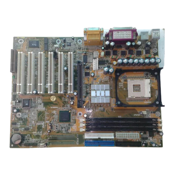
Motherboard Description SY-P4IS2 1-4 SY-P4IS2 MOTHERBOARD LAYOUT PS/2 KB PS/2 Mouse PS/2 Mouse Connector Connector FDC1 ATX Power USB 1 USB 2 COM A COM B AOUT AGP Slot AMIC IDE 2 IDE 1 AGAME PCI#1 Sigmatel C M O S C l e a r... -
Page 9: Sy-P4Is2 Motherboard Components
Motherboard Description SY-P4IS2 1-5 SY-P4IS2 MOTHERBOARD COMPONENTS F G H... - Page 10 Motherboard Description SY-P4IS2 ATX12V 4-Pin(+12V) Connector ATX12V 6-Pin(+3.3V, +5V) Connector Socket 478 Connector Intel i845 North Bridge Chip CPU Cooling Fan Connector DIMM Bank ATX Power Connector Floppy Disk Drive (FDD) Bus Mastering E-IDE/ATAPI Ports CMOS Clear Jumper Intel FW82801BA South Bridge Chip...
-
Page 11: Chipset
Motherboard Description SY-P4IS2 1-6 CHIPSET The Intel® 845 chipset Memory Controller Hub (MCH) is designed for use with the Intel® Pentium 4 processor and Northwood processor in the 478-pin package. The Intel ® 845 chipset MCH role in a system is to manage the flow of information between its four interfaces: the System Bus, the memory interface, the AGP port, and the Hub Interface. - Page 12 Motherboard Description SY-P4IS2 AGTL+ system bus with integrated termination supporting 32-bit system bus addressing Up to 3GB (w/ 512-Mb technology) of PC133 SDRAM 1.5V AGP interface with 4x SBA/Data Transfer and 2x/4x Fast Write capability 8 bit, 66 MHz 4x Hub Interface to Intel ICH2 Distributed arbitration for highly concurrent operation 1-6.2 Intel®...
-
Page 13: Dram Interface
Motherboard Description SY-P4IS2 AGP/PCI using PCI semantics and from the Hub Interface to Dram will be snooped on the system bus. Memory accesses whose addresses lie within the AGP aperture are translated using the AGP address translation table, regardless of the originating interface. - Page 14 Motherboard Description SY-P4IS2 Writes. AGP semantic cycles to DRAM are not snooped on the system bus. PCI semantic cycles to DRAM are snooped on the system bus. The MCH supports PIPE# or SBA[7:0] AGP address mechanisms, but not both simultaneously. Either the PIPE# or the SBA[7:0] mechanism must be selected during system initialization.
-
Page 15: System Interrupts
Motherboard Description SY-P4IS2 system bus target speed is 400MHz. The MCH does not require any relationship between the HCLKIN host clock and the 66MHz clock generated for AGP and Hub Interface; they are totally asynchronous from each other. The AGP and Hub Interface runs at a constant 66MHz base frequency. -
Page 16: Ide Support
Motherboard Description SY-P4IS2 including the ones originating from the MCH. The Intel® 845 chipset MCH supports interrupt re-direction for inter-processor interrupts (IPIs) as well as upstream interrupt memory writes. For message based interrupts, system write buffer coherency is maintained by relying on strict ordering of Memory Writes. The Intel® 845 chipset... -
Page 17: I/O Interface Controller
Motherboard Description SY-P4IS2 diskett’s 2,490 tracks per inch (tpi) containing up to 120MB of data storage. A conventional diskette uses 135 tpi for 1.44MB of data storage. LS-120 drivers are ATAPI-compatible and connect to the motherboard’s IDE interface. (LS-120 drivers are also available with SCSI and parallel port interfaces.) Some versions of Windows 95 and Windows NT... - Page 18 Motherboard Description SY-P4IS2 Keyboard Controller 38 General Purpose I/O Pins External IRQ Input Routing Capability ITE innovative automatic power-failure resume and power button de-bounce The Setup program provides configuration option for the I/O controller. 1-7.1 Low Pin Count Interface Comply with Intel Low Pin Count Interface Specification Rev. 1.0...
- Page 19 Motherboard Description SY-P4IS2 Provides over temperature beep tone warning 1-7.5 Two 16C550 UARTs Supports two standard Serial Ports Supports IrDA 1.0/ASKIR protocols Supports Smart Card Reader protocols 1-7.6 Smart Card Reader Compliant with Personal Computer Smart Card (PC/SC) Working Group standard...
-
Page 20: Wake On Lan Technology
Motherboard Description SY-P4IS2 1-7.10 38 General Purpose I/O Pins Input mode supports either switch de-bounce or programmable external IRQ input routing Output mode supports 2 sets of programmable LED blinking periods 1-7.11 External IRQ Input Routing Capability Provides IRQ input routing through GPIO input mode Programmable registers for IRQ routing ¿... - Page 21 Motherboard Description SY-P4IS2 capable of delivering +5V ±5 % at 720 mA. Failure to provide adequate standby current when implementing Wake on LAN can damage the power supply.
-
Page 22: Chapter 2 Hardware Installation
SY-P4IS2 Chapter 2 HARDWARE INSTALLATION Congratulations on your purchase of SY-P4IS2 Motherboard. You are about to install and connect your new Motherboard. Note: Do not unpack the Motherboard from its protective anti-static packaging until you have made the following preparations. -
Page 23: Unpacking The Motherboard
Hardware Installation SY-P4IS2 2-2 UNPACKING THE MOTHERBOARD When unpacking the Motherboard, check for the following items: u The SY-P4IS2 Intel i845 AGP/PCI/CNR Motherboard u The Quick Start Guide u The Installation CD-ROM u SOYO Bonus Pack CD-ROM u One IDE Device ATA 100 Flat Cable... -
Page 24: Installation Guide
Hardware Installation SY-P4IS2 2-3 INSTALLATION GUIDE We will now begin the installation of the Motherboard. Please follow the step-by-step procedure designed to lead you to a complete and correct installation. Warning: Turn off the power to the Motherboard, system chassis, and peripheral devices before performing any work on the Motherboard or system. -
Page 25: Cpu Installation
Hardware Installation SY-P4IS2 2-3.1 CPU Installation To perform the installation of your new SY-P4IS2 Motherboard, follow the steps below: Mark your CPU Frequency: Record the working frequency of your mPGA CPU that should be clearly marked on the CPU cover. - Page 26 Hardware Installation SY-P4IS2 Align the blunt edge of the CPU with the matching pinhole distinctive edge on the socket. Seat the processor in the socket completely and without forcing.
- Page 27 Hardware Installation SY-P4IS2 Then close the socket handle to secure the CPU in place. Remember to connect the CPU Cooling Fan to the appropriate power connector on the Motherboard. The fan is a key component that will ensure system stability. The fan prevents overheating,...
-
Page 28: Sdram Memory Module Installation
Hardware Installation SY-P4IS2 2-3.2 SDRAM Memory Module Installation Directly supports one SDR SDRAM channel, 64b wide (72b with ECC), providing support max of 3 Double-Sided DIMMs with unbuffered PC133, No reqistered DIMM support. The largest memory capacity possible is 3GB. -
Page 29: Motherboard Connector
Hardware Installation SY-P4IS2 Memory Configuration Table Number of Memory DIMM 1 DIMM 2 DIMM 3 Modules RAM Type SDRAM Memory Module Size (MB) 32/64/128/256/512 MB/1 GB 2-3.3 Motherboard Connector 2-3.3.1 IDE Device Installation (HDD, CD-ROM) Pin-1 IDE 2 IDE 1... - Page 30 Hardware Installation SY-P4IS2 2-3.3.2 Floppy Drive Installation Pin -1 Floppy Drive Connector The system supports 5 possible floppy drive types: 720 KB, 1.2 MB, 1.44 MB, 2.88 MB, and LS-120. In addition, this Motherboard supports a 3-mode (720KB/1.2MB/1.44MB) floppy commonly used in Japan.
- Page 31 Hardware Installation SY-P4IS2 2-3.3.3 Front Panel Connections Power Reset PWRBT Keylock ACPI Speaker Plug the computer case's front panel devices to the corresponding headers on the Motherboard. 1. Power LED & KeyLock Plug the Power LED cable into the 5-pin Keylock header.
- Page 32 Hardware Installation SY-P4IS2 2. Reset Plug the Reset push-button cable into the 2-pin Reset header on the Motherboard. Pushing the Reset button on the front panel will cause the system to restart the boot-up sequence. Reset Pin Assignment Power Good 3.
- Page 33 Hardware Installation SY-P4IS2 5. IDE LED Attach the 2-pin IDE device LED cable to the corresponding IDE LED header on the Motherboard. This will cause the LED to lighten when an IDE (HDD, CD-ROM) device is active. HDD LED Pin Assignment LED Anode LED Cathode 6.
-
Page 34: Back Panel Connections
Hardware Installation SY-P4IS2 2-3.3.4 Back Panel Connections All external devices such as the PS/2 keyboard, PS/2 mouse, printer, modem, USB can be plugged directly onto the Motherboard back panel. Only after you have fixed and locked the Motherboard to the computer case can you start connecting the external peripheral devices. - Page 35 Hardware Installation SY-P4IS2 1. Onboard Serial Ports COMA/COMB External peripherals that use serial transmission scheme include: serial mouse, and modem. Plug the serial device cables directly into the COMA/COMB 9-pin male connectors located at the rear panel of the Motherboard.
-
Page 36: Usb3 Usb
Hardware Installation SY-P4IS2 5. Universal Serial Bus USB1/USB2/(USB3, USB4) This Motherboard provides four USB ports for your additional devices. Plug the USB device jack into the available USB connector USB1 or USB2. Standard device drivers come with the Win98 for commonly used USB devices. - Page 37 Hardware Installation SY-P4IS2 2-3.3.5 Other Connections 1. Wake-On-LAN (WOL) Attach the 3-pin connector from the LAN card which supports the Wake-On-LAN (WOL) function to the JP10 header on the Motherboard. This WOL function lets users wake up the connected computer through the LAN card.
- Page 38 Hardware Installation SY-P4IS2 2. Standard Infrared (SIRCON) Plug the 5-pin infrared device cable to the SIRCON header. This will enable the infrared transfer function. This Motherboard meets both the ASKIR and HPSIR specifications. Please install according to the following pin assignment:...
- Page 39 CPUFAN connector on the Motherboard. The fan will stop when the system enters into Suspend Mode. (Suspend mode can be enabled from the BIOS Setup Utility, [SOYO COMBO] menu.) To avoid damage to the system, install according to the following pin...
-
Page 40: System Fan
Hardware Installation SY-P4IS2 (2) Chassis Cooling Fan Some chassis also feature a cooling fan. This Motherboard features a CHAFAN connector to provide 12V power to the chassis fan. Connect the cable from the chassis fan to the CHAFAN 3-pin connector. Install according... - Page 41 Hardware Installation SY-P4IS2 4. Smart Card Reader 2-3.3.6 AGP VGA Card Insert VGA card into the AGP or PCI expansion slots according to card specifications.
-
Page 42: Atx Power
Hardware Installation SY-P4IS2 2-3.3.7 ATX12V Power Supply The ATX12V power supply includes a 20-pin ATX connector that comply with the ATX specification, Version 2.03 for M/B specification, a new 4-pin receptacle/header combination--the +12V power connector--has been defined. The presence of the +12V power connector indicates that a power supply is ATX12V;... -
Page 43: Atx Power
Hardware Installation SY-P4IS2 specification. * Note: If you use the Wake-On-LAN (WOL) function, make sure the ATX power supply can support at least 720 mA on the 5V Standby lead (5VSB). Please install the ATX power according to the following pin assignment:... - Page 44 Hardware Installation SY-P4IS2 2-3.3.8 CNR (Communication Networking Riser)Connector This motherboard supports CNR (Communication Networking Riser) slot...
-
Page 45: Jumper Setting
Hardware Installation SY-P4IS2 2-3.4 Jumper Setting On Board Audio Codec Enable/Disable (SW1) Step 1. Pin 1 Pin 2 Enable Disable CNR MR Card-CODEC OPTION (JP4) Step 2. CNR MR Card-CODEC Primary Secondary OPTION Open JP4 Setting Short JP4 CMOS Clear (JP5) In some cases the CMOS memory may contain wrong data, follow the steps below to clear the CMOS memory. -
Page 46: Power On
Hardware Installation SY-P4IS2 Note: You must unplug the ATX power cable from the ATX power connector when performing the CMOS Clear operation. 2-3.5 Power On You have now completed the hardware installation of your Motherboard successfully. 1. Turn the power on 2. -
Page 47: Quick Bios Setup
This Motherboard does not use any hardware jumpers to set the CPU frequency. Instead, CPU settings are software configurable with the BIOS [SOYO COMBO SETUP]. The [SOYO COMBO SETUP] combines the main parameters that you need to configure, all in one menu, for a quick setup in BIOS. -
Page 48: Troubleshooting At First Start
2-3.7 Troubleshooting at First Start Video (no display) related issues I built a new computer system using a Soyo board and nothing happens when turning it on, no video and no beeps from the PC speaker. What is happening and how can it be fixed? No screen and no beeps mean that your CPU and motherboard do not work at all. -
Page 49: Bios Issues
5EH_2CA1 (meaning revision 2CA1 for the SY-5EH board) or 6BA+ IV_2AA2 which means SY-6BA+ IV motherboard with 2AA2 bios. Where can I find the latest BIOS of my motherboard? Please go to the technical support page of one of the SOYO websites www.soyo.com.tw (Taiwan: ), and look up your motherboard to find the latest BIOS revision. -
Page 50: Audio Issues
Why? If you are sure that the modem driver has been installed correctly, then you need to install the south bridge driver from the SOYO CD, this is because Windows does not properly recognize relatively new chipsets. - Page 51 Then put back the peripherals one by one to identify which one causes the lockup. I can not get my board to run properly. Please make sure you have the latest bios and driver from the SOYO web site at: http://www.soyo.com Note on Over-clocking Capability The SY-P4IS2 provides over-clocking capability.
-
Page 52: Power Off
Hardware Installation SY-P4IS2 Note: SOYO does not guarantee system stability if the user over clocks the system. Any malfunctions due to over-clocking are not covered by the warranty. 2-3.8 Power Off There are two possible ways to turn off the system: Use the Shutdown command in the Start Menu of Windows 95/98 to turn off your computer. -
Page 53: Chapter 3 Bios Setup Utility
BIOS Setup Utility SY-P4IS2 Chapter 3 BIOS SETUP UTILITY This Motherboard's BIOS setup program uses the ROM PCI BIOS program from Award Software Inc. To enter the Award BIOS program's Main Menu: Turn on or reboot the system. After the diagnostic checks, press the [Del] key to enter the Award BIOS Setup Utility. - Page 54 BIOS Setup Utility SY-P4IS2 Hot Keys: Function keys give you access to a group of commands throughout the BIOS utility. Function Command Description Gives the list of options available for each General Help item. Previous Restore the old values. These are the values Values that the user started the current session with.
- Page 55 BIOS Setup Utility SY-P4IS2 SAVE AND EXIT SETUP Select the [SAVE & EXIT SETUP] option from the Main Menu to save data to CMOS and exit the setup utility. This option saves all your changes and causes the system to reboot.
-
Page 56: Soyo Combo Setup
<DEL> key during the system diagnostic checks to enter the Award BIOS Setup program. The CMOS SETUP UTILITY will display on screen. Then, select the [SOYO COMBO SETUP] option from the main menu and press the <Enter> key. - Page 57 BIOS Setup Utility SY-P4IS2 3-1.1 Quick CPU Frequency Setup Setting Description Note Set the [CPU Frequency Select] Default Auto Frequency field to “Manual”, to be able to Manual Select change the CPU frequency 1 MHz stepping. Frequency Min=100 Press “Page Up”/”Page Down” key to Over...
- Page 58 BIOS Setup Utility SY-P4IS2 3-1.3 CPU Vcore Select Setting Description Note CPU Vcore Default This function adjust Default Select the CPU voltage. 1.100V, 1.125V, 1.150V, 1.175V, 1.200V, 1.225V, 1.250V, 1.275V, 1.300V, 1.325V, 1.350V, 1.375V, 1.400V, 1.425V, 1.450V, 1.475V, 1.500V, 1.525V, 1.550V, 1.575V, 1.600V,...
- Page 59 BIOS Setup Utility SY-P4IS2 DRAM RAS# This item allows you to control to CAS# DRAM RAS to CAS delay time. Default Delay DRAM RAS# This item allow you to control DRAM Precharge RAS precharge time. Default 3-1.5 System Boot Control Settings...
-
Page 60: Standard Cmos Setup
BIOS Setup Utility SY-P4IS2 3-2 STANDARD CMOS SETUP Select the [STANDARD CMOS SETUP] option from the Main Menu and press [Enter] key. CMOS Setup Utility – Copyright ( C ) 1984-2001 Award Software Standard CMOS Features Date (mm:dd:yy) Mon, May 7 2001... - Page 61 BIOS Setup Utility SY-P4IS2 3-2.2 Hard Disks Type & Mode Choose the type and mode for the hard disks that you have already installed. Primary Setting Description Note (Secondary) Master & Slave IDE HDD Press To auto-detect the HDD’s size,...
- Page 62 BIOS Setup Utility SY-P4IS2 3-2.4 Others Optional Setting Description Note Video EGA/VGA Select the video mode. Default CGA 40 CGA 80 MONO (Monochrome) Halt On ALL Errors When the BIOS detects system Default errors, this function will stop the No Errors system.
-
Page 63: Advanced Bios Features
BIOS Setup Utility SY-P4IS2 3-3 ADVANCED BIOS FEATURES Select the [Advanced BIOS Features] option from the Main Menu and press [Enter] key. CMOS Setup Utility – Copyright ( C ) 1984-2001 Award Software Advanced BIOS Features Virus Warning Disabled Item Help CPU L1 &... - Page 64 BIOS Setup Utility SY-P4IS2 3-3.1 Virus Warning Setting Description Note Virus Warning Disabled Allows you to choose the Default VIRUS warning feature for Enabled IDE Hard Disk boot sector protection. If this function is enabled and someone attempt to write data into this area,...
- Page 65 BIOS Setup Utility SY-P4IS2 3-3.6 Gate A20 Options Setting Description Note Gate A20 Normal A pin in the keyboard controller Options controls GateA20. Fast Lets chipset control GateA20. Default 3-3.7 Typematic Settings Typematic Settings Setting Description Note Typematic Disabled Keystrokes repeat at a rate...
- Page 66 BIOS Setup Utility SY-P4IS2 3-3.8 Security Option Use this feature to prevent unauthorized system boot-up or use of BIOS Setup. The following table describes the security settings. Setting Description Note Security Option System Each time the system is booted, the password prompt appears.
- Page 67 BIOS Setup Utility SY-P4IS2 Small Logo(EPA) Show Setting Description Note EPA LOGO LOG0 Allows user to display SOYO Default SELECT logo or own logo. Logo-0 shows LOG1 SOYO logo, Logo-1 shows user logo. Small Disabled Set Enabled to Show Logo(EPA).
-
Page 68: Advanced Chipset Features
BIOS Setup Utility SY-P4IS2 3-4 ADVANCED CHIPSET FEATURES Caution: Change these settings only if you are already familiar with the Chipset. The [Advanced Chipset Features] option changes the values of the chipset registers. These registers control the system options in the computer. - Page 69 BIOS Setup Utility SY-P4IS2 3-4.1 CHIPSET FEATURES SETUP CHIPSET Setting Description Note FEATURES System BIOS Disabled Default Cacheable Enabled The ROM area F0000H-FFFFFH is cacheable. Video BIOS Disabled Default Cacheable Enabled The video BIOS C0000H-C7FFFH is cacheable. Video RAM Disabled...
-
Page 70: Integrated Peripherals
BIOS Setup Utility SY-P4IS2 3-5 INTEGRATED PERIPHERALS Caution: Change these settings only if you are already familiar with the Chipset. The [INTEGRATED PERIPHERALS] option changes the values of the chipset registers. These registers control the system options in the computer. - Page 71 BIOS Setup Utility SY-P4IS2 The following tables describe each field in the INTEGRATED PERIPHERALS Menu and provide instructions on how to configure the IDE controls, FDC controls, and the onboard serial and parallel ports. 3-5.1 IDE Device Controls IDE Controls...
- Page 72 BIOS Setup Utility SY-P4IS2 3-5.3 IDE HDD Block Mode Setting Description Note IDE HDD Block Mode Disabled Enabled Invokes multi-sector Default transfer instead of one sector per transfer. Not all HDDs support this function. 3-5.4 Others Optional Setting Description Note...
- Page 73 BIOS Setup Utility SY-P4IS2 3-5.6 Onboard Serial Ports Onboard Serial Setting Description Note Ports Onboard Disabled Serial Port 1 / 3F8/IRQ4 Choose serial port 1 & 2's I/O Default Serial Port 2 address. (port 1) Do not set port 1 & 2 to the...
- Page 74 BIOS Setup Utility SY-P4IS2 3-5.8 Others Optional Setting Description Note PWRON After The system will switch on PWR-Fail when power comes back after a power failure. The system will remain off Default when power comes back after a power failure.
-
Page 75: Power Management Setup
BIOS Setup Utility SY-P4IS2 3-6 POWER MANAGEMENT SETUP The [POWER MANAGEMENT SETUP] sets the system's power saving functions. CMOS Setup Utility – Copyright ( C ) 1984-2001 Award Software Power Management Setup ACPI Suspend Type S1(POS) Item Help Power Management... - Page 76 BIOS Setup Utility SY-P4IS2 3-6.1 Power Management Controls Power Setting Description Note Management Controls ACPI Suspend S1(POS) The system will enter the S1 Default Type state during suspend. (Low S3(STR) latency wake up) Power User Define Lets you define the HDD and...
- Page 77 BIOS Setup Utility SY-P4IS2 Power Management Controls (Continued) Power Setting Description Note Management Controls HDD Power Disabled Default Some older Down 1-15Min When the set time has model HDDs elapsed, BIOS sends a may not support command to the HDD to this advanced power down.
- Page 78 BIOS Setup Utility SY-P4IS2 3-6.2 Reload Global Timer Events Power Down Setting Description Note & Resume Events IDE0, IDE1 Disabled Default Ø Primary Enabled In effect, the system remains alert Ø Secondary for anything which occurs to a device which is configured as Enabled.
-
Page 79: Pnp/Pci Configuration Setup
BIOS Setup Utility SY-P4IS2 3-7 PNP/PCI CONFIGURATION SETUP This option sets the Motherboard's PCI Slots. CMOS Setup Utility – Copyright ( C ) 1984-2001 Award Software PnP/PCI Configurations Reset Configuration Data Disabled Item Help Resources Controlled By Auto (ESCD) Menu Level 4... - Page 80 BIOS Setup Utility SY-P4IS2 3-7.1 PNP/PCI Configuration Controls PNP/PCI Setting Description Note Controls Reset Disabled Retain PnP configuration Default Configuration data in BIOS. Data Enabled Reset PnP configuration data in BIOS. Resources Manual BIOS does not manage PCI/ISA PnP Controlled By card IRQ assignment.
- Page 81 BIOS Setup Utility SY-P4IS2 PNP/PCI Configuration Setup (Continued) PNP/PCI Setting Description Note Setup Interrupt How to set the BIOS to release the IRQ to the PnP Interrupt pool: Line PnP / PCI configuration Integrated Peripherals IRQ 15 IRQ 15: PCI / ISA PnP On-Chip Secondary PCI IDE: disabled...
-
Page 82: Pc Health Status
BIOS Setup Utility SY-P4IS2 3-8 PC HEALTH STATUS This option sets the Motherboard's PC Health Status. CMOS Setup Utility – Copyright ( C ) 1984-2001 Award Software PC Health Status Shutdown Temperature Disabled Item Help Vcore 1.66 V VCC 1.8V 1.79 V... - Page 83 BIOS Setup Utility SY-P4IS2 3-8.1 CPU Device Monitoring CPU Device Setting Description Note Monitoring Shutdown Disabled This item allows you to set up Default Temperature the CPU shutdown Temperature. 40°C/104°F, This item only effective under 45°C/113°F, Windows 98 ACPI mode.
-
Page 84: Load Fail-Safe Defaults
BIOS Setup Utility SY-P4IS2 3-9 LOAD FAIL-SAFE DEFAULTS Select the [Load Fail-Safe Defaults] option from the Main Menu to load the system values you have previously saved. This option is recommended if you need to reset the system setup and to retrieve the old values. -
Page 85: Load Optimized Defaults
BIOS Setup Utility SY-P4IS2 3-10 LOAD OPTIMIZED DEFAULTS Select the [Load Optimized Defaults] option from the Main Menu to load the system values you have previously saved. This option is recommended if you need to reset the system setup and to retrieve the old values. -
Page 86: Supervisor Password
BIOS Setup Utility SY-P4IS2 3-11 SUPERVISOR PASSWORD Based on the setting you have made in the [Security Option] of the [BIOS FEATURES SETUP] section, the password prevents access to the system or the setup program by unauthorized users. Follow this procedure to set a... -
Page 87: User Password
BIOS Setup Utility SY-P4IS2 Enter your new password and press [Enter]. The following message appears, prompting to confirm the new password: Confirm Password: Re-enter your password and then press [Enter] to exit to the Main Menu. This diagram outlines the password selection procedure: «... -
Page 88: Boot Menu
BIOS Setup Utility SY-P4IS2 Boot Menu Boot Menu enables user to boot-up on different boot device without going into the BIOS setup. To enable boot Menu, press “ESC” after memory initialization, user will see a device menu, in which user can choose on which device they wish to boot from. -
Page 89: Chapter 4 Drivers Installation
System other than Windows 95/98/98SE/ME. Your SY-P4IS2 Motherboard comes with a CD-ROM labeled "SOYO CD." The SOYO CD contains (1) the user's manual file for your new Motherboard, (2) the drivers software available for installation, and (3) a database in HTML format with information on SOYO Motherboards and other products. - Page 90 Drivers installation SY-P4IS2 The user's manual files included on the SOYO CD are in PDF (Postscript Document) format. In order to read a PDF file, the appropriate Acrobat Reader software must be installed in your system. Note: The Start Up program automatically detects if the Acrobat Reader utility is already present in your system, and otherwise prompts you on whether or not you want to install it.
- Page 91 Drivers installation SY-P4IS2 Step 2. Install Drivers and Utilities Click the Install Drivers button to display the list of drivers software that can be installed with your Motherboard. The Start Up program displays the drivers available for the particular model of Motherboard you own. We recommend that you only install those drivers.
- Page 92 Step 3. Check the Latest Releases Click the 'Check the latest Releases' button to go the SOYO Website to automatically find the latest BIOS, manual and driver releases for your motherboard. This button will only work if your computer is connected to the internet through a network or modem connection.