Table of Contents
Advertisement
Advertisement
Table of Contents

Related Manuals for Foxconn 45CMX


Summary of Contents for Foxconn 45CMX
- Page 1 45CMX/45GMX Series Motherboard User’s Manual...
- Page 2 Statement: This manual is the intellectual property of Foxconn, Inc. Although the information in this manual may be changed or modified at any time, Foxconn does not obligate itself to inform the user of these changes. Trademark: All trademarks are the property of their respective owners.
-
Page 3: Declaration Of Conformity
HON HAI PRECISION INDUSTRY COMPANY LTD 66 , CHUNG SHAN RD., TU-CHENG INDUSTRIAL DISTRICT, TAIPEI HSIEN, TAIWAN, R.O.C. declares that the product Motherboard 45CMX/45CMX-K/45GMX is in conformity with (reference to the specification under which conformity is declared in accordance with 89/336 EEC-EMC Directive) ■... - Page 4 Declaration of conformity Trade Name: FOXCONN Model Name: 45CMX/45CMX-K/45GMX 45CMX/45CMX-K/45GMX Responsible Party: PCE Industry Inc. Address: 458 E. Lambert Rd. Fullerton, CA 92835 Telephone: 714-738-8868 Facsimile: 714-738-8838 Equipment Classification: FCC Class B Subassembly Type of Product: Motherboard Manufacturer: HON HAI PRECISION INDUSTRY...
-
Page 5: Installation Precautions
Installation Precautions ■ Electrostatic discharge (ESD) is the sudden and momentary electric current that flows between two objects at different electrical potentials. Normally it comes out as a spark which will quickly damage your electronic equipment. Please wear an electrostatic discharge (ESD) wrist strap when handling components such as a motherboard, CPU or memory. -
Page 6: Table Of Contents
TAble of CoNTeNTS Chapter 1 Product Introduction Product Specifications ..............2 Layout ................... 4 Back Panel Connectors ..............5 Chapter 2 Hardware Install Install the CPU and CPU Cooler ..........8 Install the Memory ..............11 Install an Expansion Card ............13 Install other Internal Connectors .......... - Page 7 About & Help ................. 64 FOX LOGO ................. 65 FOX DMI ..................66 Technical Support : Support Website : http://www.foxconnchannel.com Support Website : http://www.foxconnchannel.com/support/online.aspx or http://www.foxconnsupport.com Worldwide e-mail Support : pcebg-cisg-support@foxconn.com CPU, Memory, VGA Compatibility Supporting Website : http://www.foxconnchannel.com/product/Motherboards/compatibility. aspx...
- Page 8 Thank you for buying Foxconn 45CMX/45GMX series motherboard. Foxconn products are engineered to maximi�e computing power, providing only what you need for break-through performance. With advanced overclocking capability and a range of connectivity features for today multi-media computing requirements, 45CMX/ 45GMX enables you to unleash more power from your computer.
-
Page 9: Product Specifications
1-1 Product Specifications Support LGA775 socket Intel ® CPU: 2 Duo / Pentium ® 4 Extreme Edition / Core Pentium ® D / Pentium ® 4 / Celeron ® / Celeron ® D processors processors Front Side Bus 1333(oc�)/1066/800/533 M��� FSB 1333(oc�)/1066/800/533 M���... - Page 10 Back Panel 1 x PS/2 Keyboard port Connectors 1 x PS/2 Mouse port 1 x Serial port 1 x Parallel port 4 x USB 2.0 ports 1 x RJ-45 LAN port 1 x VGA port 6-channel audio ports (Refer Realtek Audio Driver) Hardware Monitor System voltage detection CPU/System/NB temperature detection...
-
Page 11: Layout
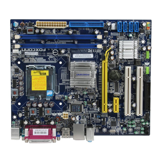
1-2 layout 1. 4-pin ATX 12V Power Connector 4-pin ATX 12V Power Connector 14. USBPWR1 Jumper 14. USBPWR1 Jumper USBPWR1 Jumper 2. IrDA Connector 15. Chassis Intruder Connector 15. Chassis Intruder Connector 3. SPDIF OUT Connector 3. SPDIF OUT Connector 16. -
Page 12: Back Panel Connectors
1-3 back Panel Connectors PS/2 Mouse Port Parallel Port Port LAN Port Line In Line Out Microphone In PS/2 Keyboard Serial Port VGA Port USB 2.0 Ports Audio Ports Port 1. PS/2 Mouse Port Use the upper port (green) to connect a PS/2 mouse. 2. - Page 13 No Link 100M Green Data Activity Orange 10/100Mb/s Connection Blinking No Link No Link 10Mb/s Connection 1000M Green Data Activity Green 100Mb/s Connection Blinking Orange 1000Mb/s Connection Active Link 45CMX supports 10/100 Mb/s Ethernet. 45CMX-K / 45GMX support 1Gb/s Ethernet.
- Page 14 This chapter introduces the hardware installation process, including the installation of the CPU, memory, power supply, slots, pin headers and the mounting of jumpers. Caution should be exercised during the installation of these modules. Please refer to the motherboard layout prior to any installation and read the contents in this chapter carefully.
-
Page 15: Install The Cpu And Cpu Cooler
2-1 Install the CPU and CPU Cooler Read the following guidelines before you begin to install the CPU : ■ Make sure that the motherboard supports the CPU. ■ Always turn off the computer and unplug the power cord from the power supply before installing the CPU to prevent hardware damage. - Page 16 Follow the steps to install the CPU onto the CPU socket : Before installing the CPU, make sure to turn off the computer and unplug the power cord from the power outlet to prevent damage to the CPU. 1. Remove protective socket cover. Remove protective socket cover.
-
Page 17: Install The Cpu Cooler
Install the CPU Cooler Follow the steps below to correctly install the CPU cooler on the motherboard. (The following procedures use Foxconn ® cooler as the example.) 1. Apply and spread an even thermal 2. Place the four bolts of the CPU grease on the surface of CPU. -
Page 18: Install The Memory
2-2 Install the Memory Read the following guidelines before you begin to install the memory : ■ Make sure that the motherboard supports the memory. It is recommended that memory of the same capacity, brand, speed, and chips be used. ■... -
Page 19: Installing A Memory
Installing a Memory Before installing a memory module, make sure to turn off the computer and unplug the power cord from the power outlet to prevent damage to the memory module. Be sure to install DDR2 DIMMs on this motherboard. Notch If you take a look at front side of memory module, it has asymmetric pin counts on both sides separated by a notch in the middle, so it can only fit in one direction. -
Page 20: Install An Expansion Card
2-3 Install an expansion Card ■ Make sure the motherboard supports the expansion card. Carefully read the manual that came with your expansion card. ■ Always turn off the computer and unplug the power cord from the power outlet before installing an expansion card to prevent hardware damage. -
Page 21: Install Other Internal Connectors
2-4 Install other Internal Connectors Power Connectors This motherboard uses an ATX power supply. In order not to damage any device, make sure all the devices have been installed properly before applying the power supply. 24-pin ATX power connector : PWR1 PWR1 is the ATX power supply connector. - Page 22 Audio Connector : CD_IN CD_L GND CD_R CD_IN is a Sony standard audio connector, it can be connected to a CD/DVD-ROM drive through a CD/DVD audio cable. CD_IN PORT1_L AUD_GND PORT1_R PRESENCEJ Audio Connector : f_AUDIo PORT2_R SENSE1_RETURN The audio connector supports HD Audio standard. SENSE_SEND EMPTY PORT2_L...
-
Page 23: Front Panel Connector
front Panel Connector : fP1 This motherboard includes one connector for connecting the front panel switch and LED Indicators. HDD-LED PWR-LED Hard Disk leD Connector (HDD-leD) RESET-SW PWR-SW Connect to the chassis front panel IDE indicator LED. It EMPTY indicates the active status of the hard disks. This 2-pin connector is directional with +/- sign. -
Page 24: Jumpers
2-5 Jumpers For some features needed, users can change the jumper settings on this motherboard to modify them. This section explains how to use the various functions of this motherboard by changing the jumper settings. Users should read the following content carefully prior to modifying any jumper setting. Description of Jumpers 1. - Page 25 ■ Disconnect the power cable before adjusting the jumper settings. ■ Do not clear the CMOS while the system is turned on. USb device wake-up Jumper: USbPWR1 / USbPWR2 1. Set the jumper to pins 1-2 (+5V) to wake up the computer from S1 sleep mode using the connected USB devices.
- Page 26 This chapter tells how to change system settings through the BIOS Setup menus. Detailed descriptions of the BIOS parameters are also provided. You have to run the Setup Program when the following cases occur : 1. An error message appears on the screen during the system Power On Self Test (POST) process.
-
Page 27: Enter Bios Setup
enter bIoS Setup The BIOS is the communication bridge between hardware and software, correctly setting up the BIOS parameters is critical to maintain optimal system performance. Power on the computer, when the message "Press TAb to show PoST screen, Del to enter SeTUP, eSC to enter boot Menu"... - Page 28 ► Power Management Setup All the items related with Green function features can be set up through this menu. ► PC Health Status This setup enables you to read/change Fan speeds, and displays temperatures and voltages of your CPU/System. ► Load Optimized Defaults The optimal performance settings can be loaded through this menu.
-
Page 29: Standard Cmos Features
Standard CMoS features This submenu is used to set up the standard BI�S features, such as the date, time, floppy drive and so on. Use the arrow up/down keys to select an item, then use the <+> or <-> keys to change the setting. - Page 30 Award (Phoenix) bIoS is supporting 3 HDD modes : CHS, lbA and large. For HDD <528MB For HDD >528MB & Supporting LBA (Logical Block Addressing) Large For HDD>528MB but not supporting LBA Note: Set to [Auto] , the system can detect the hard disk and select the HDD mode automatically.
-
Page 31: Fox Central Control Unit
fox Central Control Unit Phoenix - AwardBIOS CMOS Setup Utility Fox Central Control Unit [SuperBIOS-Protect] Item Help Help SuperBIOS-Protect [Disabled] Disabled Menu Level ► [SuperSpeed] Current CPU Frequency 2134MH� Current FSB Frequency 1066M��� Current DRAM Frequency 533MH� CPU Clock Ratio [ 8 X] Auto detect PCI Clk [Enabled]... - Page 32 [Manual] - It means you can manually select a CPU clock to run your system. Any selected setting must be saved and exit BIOS to activate it. More detailed descriptions of FIS feature can be found in FOX One utility of Chapter 4. ►...
- Page 33 The following 5 settings are valid only when the DRAM Timing Selectable is set to [Manual]. ► CAS Latency Time (tCL) This item controls the CAS latency The CAS Latency is the number of clock cycles that elapse from the time the request for data is sent to the actual memory location until the data is transmitted from the module.
-
Page 34: Advanced Bios Features
Advanced bIoS features Phoenix - AwardBIOS CMOS Setup Utility Advanced BIOS Features ► CPU Feature [Press Enter] Item Help Press Enter ► Removable Device Priority [Press Enter] ► �ard Disk Boot Priority [Press Enter] Menu Level ► CPU L1 & L2 Cache [Enabled] First Boot Device [Hard Disk]... -
Page 35: Cpu Feature
This item is used to enable or disable APIC function. APIC interrupt subsystems can have as many IRQs as are required in a specific machine. APICs are beneficial for the following reasons : • APICs can contribute to resolving resource conflicts in the PC platform. •... - Page 36 Generally, the Thermal Monitor should not be activated immediately on booting as the processor will be under a heavy load during the booting process. Lower delay time unnecessarily reduces the processor's performance during the booting up process. Therefore, to ensure optimal booting performance, the activation of the Thermal Monitor must be delayed for a set period of time.
-
Page 37: Advanced Chipset Features Advanced Chipset Features
Advanced Chipset features Phoenix - AwardBIOS CMOS Setup Utility Advanced Chipset Features Enabled System BIOS Cacheable [Enabled] Item Help Video BIOS Cacheable [Disabled] Menu Level ► ** VGA Setting ** PEG/Onchip VGA Control [Auto] On-Chip Frame Buffer Si�e [ 8MB] DVMT Mode [DVMT] DVMT/FIXED Memory Si�e... - Page 38 initiali��ation. This fixed amount of memory will provide the user with a guaranteed graphics memory at all times, and will no longer be available to the OS. DVMT is an enhancement of the UMA concept, wherein the graphics driver allocates memory as needed for running graphics applications.
-
Page 39: Integrated Peripherals
Integrated Peripherals Phoenix - AwardBIOS CMOS Setup Utility Integrated Peripherals ► OnChip IDE Device [Press Enter] Press Enter Item Help ► �nboard Device [Press Enter] ► SuperI� Device [Press Enter] Menu Level ► ► USB Device Setting [Press Enter] ↑↓→←:Move Enter:Select +/-/PU/PD:Value F10:Save ESC:Exit F1:General �elp F5: Previous Values... - Page 40 it for troubleshooting purposes. For example, certain IDE devices may not run properly using DMA transfers when the PCI bus is overclocked. Disabling DMA support will force the drive to use the slower PIO transfer mode. This may allow the drive to work properly with the higher PCI bus speed.
-
Page 41: Onboard Device
onboard Device Phoenix - AwardBIOS CMOS Setup Utility Onboard Device A��alia/AC97 Audio Select [Auto] Auto Item Help Onboard LAN Controller [Enabled] Onboard LAN Boot ROM [Disabled] ↑↓→←:Move Enter:Select +/-/PU/PD:Value F10:Save ESC:Exit F1:General �elp F5: Previous Values F7: �ptimi��ed Defaults ► Azalia/AC97 Audio Select This item is used to select the operation of your audio controller. -
Page 42: Usb Device Setting
► Onboard FDC Controller This item is used to enable or disable the onboard FDC controller. ► Onboard Serial Port 1 This item is used to assign the I/O address and interrupt request (IRQ) for the onboard serial port 1. ►... - Page 43 ► USB Operation Mode This item is used to set the USB operation mode. If you select the [High Speed], then the USB operation mode is determined by the USB device; select [Full/Low Speed], the USB device operates on full/low speed. ►...
-
Page 44: Power Management Setup
Power Management Setup Phoenix - AwardBIOS CMOS Setup Utility Power Management Setup ACPI Function [Enabled] Enabled Item Help ACPI Suspend Type [S3(STR)] Soft-Off by PWR-BTTN [Instant-off] Menu Level ► HPET Support [Enabled] HPET Mode [32-bit mode] ► Power Management Events [Press Enter] ↑↓→←:Move Enter:Select +/-/PU/PD:Value F10:Save... -
Page 45: Acpi Function
► ACPI Function This item is used to enable or disable the ACPI function. ► ACPI Suspend Type This item is used to set the energy saving mode of the ACPI function. When you select “S1 (POS)” mode, the power is always on and computer can be resumed at any time. When you select “S3 (STR)”... - Page 46 ► Wake-Up by PCI card This item is used to set the system to wake up by PCI card. ► Wake-Up on LAN This item is used to set the system to wake up by LAN. ► USB KB Wake-Up from S3 This item is used to set the system to wake up by USB keyboard when it is staying at S3 (Suspend to RAM) state.
-
Page 47: Pc Health Status
PC Health Status Phoenix - AwardBIOS CMOS Setup Utility PC Health Status Case Open Warning [Disabled] ▲ Item �elp Disabled Shutdown Temperature [Disabled] █ Warning Temperature [Disabled] █ Menu Level ► CPU Vcore 1.37 V █ +3.3V 3.34 V █ 4.99 V █... - Page 48 This option is used to enable or disable smart fan function. Only when this option is enabled, you can set some correlative parameters. "Smart Fan Automatic Mode" is the principle figure of CPU smart fan function for your reference. Start 1 Temp( o C) It allows you set a temperature value from which smart fan starts its operation.
-
Page 49: Load Optimi�Ed Defaults Optimi�Ed Defaults Defaults
Load Optimized Defaults Select this option and press <Enter>. A dialogue pops out, select <Y> then press <Enter> to load the defaults; press <N> to skip. Load Optimi�ed Defaults (Y/N)? N By this default, BIOS have set the optimi�ed performance parameters of system to improve the performances of system components. - Page 50 The utility CD that came with the motherboard contains useful software and several utility drivers that enhance the motherboard features. This chapter includes the following information: ■ Utility CD content ■ Install driver and utility ■ FOX ONE ■ FOX LiveUpdate ■...
-
Page 51: Chapter 4 Cd Instruction Utility Cd Content Utility Cd Content
Utility CD content This motherboard comes with one Utility CD. You can simply put it into your CD/DVD-ROM drive, and the main menu will be displayed on your PC screen to guide you how to install. 1. Install Driver Use these options to install all the drivers for your system. You should install the drivers in order, and you need to restart your computer after all the drivers have been installed. -
Page 52: Install Driver And Utility
Step by Step Automatic Installation by One Click. Exit the program Click to visit Select to Install Select to Browse CD Foxconn's Utilities Install Drivers Drop to System website Tray 2. Install Utility You can select the specific utility to install. -
Page 53: Fox One
foX oNe FOX ONE is a powerful utility for easily modifying system settings. It also allows users to monitor various temperature values, voltage values, frequencies and fan speeds at any time. With FOX ONE, you can : ■ Modify system performance settings, such as the CPU and memory bus speeds, CPU voltages, fan speeds, and other system performance options. -
Page 54: Main Page
1. Main Page Show CPU Toolbar Information Alert Lamp Switch Button Skin Button Exit Minimum Configuration Homepage Monitor Frequency/Voltage/Fan speed/Temperature value Toolbar Use the toolbar to navigate to other pages. Alert lamp When the system is in healthy state, the alert lamp color is green. When the system is in abnormal state, the alert lamp color is red. - Page 55 Click this button to exit the program. Minimum Click this button to drop the FOX ONE to Windows system tray located at the lower right corner of your screen. Homepage Click this button to visit Foxconn motherboard website : http://www.foxconnchannel.com...
- Page 56 Configuration This menu allows you to configure : 1). Monitor interval (ms) : This is to define the interval of which different messages of system settings are to be displayed on Simple Mode screen. Minimum value is 1 second. 2). Simple Mode : To select which message of system settings are to be displayed in the Simple Mode.
- Page 57 what the CPU clock should be. Step 1 : Click Calibration icon, a message pops out to ask for continue. Select Yes. Step 2 : After data is collected, it will ask you to restart your computer now. Later on, when the FOX ONE program is activated, and F.I.S. feature (in CPU Page) is also enabled, FOX ONE will automatically adjust your CPU clock according to your system loadings.
-
Page 58: Cpu Control
2. CPU Page - CPU Control This page lets you select (or overclock) CPU clock to meet the current performance level of the system. The fastest and suitable CPU clock running for current system can be calculated by FOX ONE automatically or manually input by yourselves. Manual : You can press the up/down button to adjust your CPU clock. - Page 59 You can see the system is raising CPU clock until the system hangs. Push RESET button on the front panel of your system to restart the computer. Run FOX ONE program again, it will inform you the previous test found that 255MH�...
-
Page 60: Frequency Control
foX Intelligent Stepping (f.I.S., optional) Select FOX Intelligent Stepping will allow your system to automatically adjust your CPU clock rate based on different system loadings. For example, if you select Power Gaming, CPU clock will be driven to run at its maximum speed. While in Energy Saving, CPU will lower down its speed to a minimum. -
Page 61: Limit Setting
4. limit Setting 4.1 limit Setting - CPU Temperature This page lets you to set CPU high limit temperature and enable the alert function. Go to Limit Setting Show current CPU page temperature value Enable alert function when the CPU temperature is higher than high limit value Show current high... - Page 62 4.3 limit Setting - CPU fan This page lets you to set CPU fan low limit rpm and enable the alert function. Show current CPU fan rpm value Enable alert function when the CPU fan runs slower than the low limit rpm value Show current low limit rpm value of CPU fan...
-
Page 63: Voltage Control
4.5 limit Setting - fAN1 fan This page lets you to set FAN1 fan low limit rpm and enable the alert function. Show current FAN1 fan rpm value Enable alert function when the FAN1 fan runs slower than low limit rpm value Show current low limit rpm value of FAN1 fan Set low limit rpm by... -
Page 64: Fan Control
6. fan Page - fan Control This page lets you enable Smart Fan function or set the fan speed by manual. When Smart Fan is selected, you must use a 4-pin CPU cooler in your system. Go to Fan page Enable or disable smart fan function Set fan speed by... -
Page 65: Fox Liveupdate
foX liveUpdate FOX LiveUpdate is a useful utility to backup and update your system BIOS, drivers and utilities by local or online. Supporting Operating Systems : ■ �indows 2000 ■ Windows XP (32-bit and 64-bit) ■ �indows 2003 (32-bit and 64-bit) ■... - Page 66 1-2 local Update - backup This page can backup your system BI�S. You can click “Backup”, and key in a file name, then click “Save” to finish the backup operation. The extension of this backup file is ".BIN" for Award BIOS and ".ROM"...
-
Page 67: Online Update
2. online Update 2-1 online Update - Update bIoS This page lets you update your system BIOS from Internet. Click “start”, it will search the new BI�S from Internet. Then follow the wi��ard to finish the update operation. Click here Current information Search new BIOS from Internet... - Page 68 Select the driver to update Browse detailed information Install the selected drivers Close the window 2-3 online Update - Update Utility This page lets you update utilities from Internet. Click “start”, it will search the new utilities from Internet. Then follow the wi��ard to finish the update operation. Click here Current information Search new utilities...
-
Page 69: Configure
3. Configure 3-1 Configure - option This page lets you set auto search options. After you enable the auto search function, Fox LiveUpdate will start its searching from Internet and if any qualified item found, it will pop out a message on the task bar to inform you to do the next step. - Page 70 3-2 Configure - System This page lets you set the backup BIOS location and change different skin of the Fox LiveUpdate utility. Click here Set the location of download files or auto backup BIOS Select different skin of the software Reset to default value Determine if the FOX LiveUpdate can Apply the changes...
-
Page 71: About & Help
4. About & Help This page shows some information about FOX LiveUpdate. Click here Show information about FOX LiveUpdate... -
Page 72: Fox Logo
foX loGo FOX LOGO is a simple and useful utility to backup, change and delete the boot time Logo. The boot Logo is the image that appears on screen during POST (Power-On Self-Test). You can prepare a bitmap image (640x480) file, then use F�X L�G� to open it and change the boot time Logo. -
Page 73: Fox Dmi
foX DMI FOX DMI is a full Desktop Management Interface viewer, and it provides three DMI data formats : Report, Data Fields and Memory Dump. With DMI information, system maker can easily analy�e and troubleshoot your mother- board if there is any problem occurred. Supporting Operating Systems : ■...