Nexus NX2 Installation And Operation Manual
Hide thumbs
Also See for NX2:
- Installation and operation manual (42 pages) ,
- Installation manual (28 pages) ,
- Installation and operation manual (68 pages)

Related Manuals for Nexus NX2


Summary of Contents for Nexus NX2
- Page 1 GPS Navigator - Instrument - Installation and Operation Manual Installation and Operation Manual English English...
- Page 2 GPS NAVIGATOR...
- Page 3 If the instrument are to be used in a Nexus Network, there are some systems settings that are dependent on where the transducers are installed, i.e. at the instrument or at the Server.
-
Page 4: Table Of Contents
2.1.4 Route (ROUTE) ..................... 8 2.1.5 MAN OVER BOARD....................8 2.1.6 TIME ........................8 EXTRA NEXUS FEATURES ..................9 Installation..........................10 Mounting the instrument ....................11 Installation alternatives ....................13 CABLE CONNECTIONS ....................16 FIRST START ........................17 DEFAULT SETTINGS FROM FACTORY..............18 GPS STATUS and OPERATION.................. - Page 5 NMEA DATA ...........................46 SPECIAL NMEA AND NEXUS APPLICATIONS..............49 FAULT FINDING .......................53 TECHNICAL DATA ......................54 MAINTENANCE ........................55 WARRANTY ........................55 ABBREVIATIONS ......................56 Specifications ........................57 15.1 Technical specifications ....................57 15.2 Nexus Network introduction and user policy ..............57 Optional Accessories ......................58 Abbreviations ........................60 Warranty ........................... 61...
-
Page 6: Part Specifications
GPS NAVIGATOR Part specifications NX2 GPS Navigator is delivered with all parts for mounting. Check prior to installation. Wind Data instrument Qty. Description Reference Instrument, NX2 GPS Navigator Instrument front cover Drill template Installation and user manual Warranty card Pin bolts for instrument mounting... - Page 7 GPS NAVIGATOR...
-
Page 8: Introduction
TRUE operating, ONLY ONE WP database is in use for the whole NEXUS system. Therefore, you may store or delete waypoints, create or call up a route on any NEXUS GPS or Multi Center instruments. By adding this GPS navigator into the NEXUS series of instruments, you will benefit... -
Page 9: Basic Features
GPS NAVIGATOR Basic Features 2.1.1 Position (POS) Position is given in latitude and longitude to 3 decimal places with selectable set-up for minutes and seconds or minutes and 1 000ths of minute. Altitude in METRES or FEET can also be displayed. 2.1.2 Navigation (NAV) Course and Speed Over Ground (COG/SOG) in knots, km/h or miles/h. -
Page 10: Extra Nexus Features
1 8h and down to the last second (hh:mm:ss) before the actual start. • With the PC-interface and software, you may transmit receive waypoints; log selected data to a file; monitor NEXUS information in real time, using a GOOD LUCK AND HAPPY SAILING! -
Page 11: Installation
• The GPS antenna connected directly to the NX2 GPS Navigator instrument • The installation may also include a NX2 Server where all transducers may be connected. All data including power will pass along one cable. • The installation includes 6 major steps: 1. -
Page 12: Mounting The Instrument
Run the Nexus Network cable from the Server to the instrument. • If you want to cut the Nexus Network cable to length, disconnect 4-pole jack plug and cut the cable. Peel off about 35 mm (1,4") of the cable insulation. Remove about 6 mm (1/4") from the 3 isolated wires (the 4th wire is an earth / screen). - Page 13 GPS NAVIGATOR • Apply silicon paste to the instrument connection pins at the back of the instrument. Press the jack plug onto the instrument pins. Press the cable in to the cable leads. • Mount the connection back cover with the screw.
-
Page 14: Installation Alternatives
COMPLETE STANDALONE NX2 GPS NAVIGATOR INSTALLATION The NX2 GPS Navigator may be used stand alone without a Nexus Network. Connect the NX2 GPS Antenna or other NMEA GPS direct to the instrument. Power is also connected according to figure below. - Page 15 GPS NAVIGATOR IN A NEXUS NETWORK The NX2 GPS Navigator may be used in a Nexus Network. Connect the NX2 GPS Antenna or other NMEA GPS direct to the Server. Connect the Nexus Network cable to the instrument. Power will be supplied via the Nexus Network Cable...
- Page 16 GPS NAVIGATOR AS A REPEATER IN A NEXUS NETWORK If you already have a NX2 GPS Navigator or another GPS in the Nexus Network that is Navigating (storing the waypoints and calculates Bearing and Distance to WP etc.) you may use an other NX2 GPS Navigator as a repeater.
-
Page 17: Cable Connections
GPS NAVIGATOR CABLE CONNECTIONS The 3 m red and black power cables connect 12 V supply, ALWAYS USE WITH 3A FUSE. Cable wiring on the instruments backside. NEXUS databus and power. +12V GREEN DATA YELLOW DATA WHITE GROUND SCREEN NMEA 0183 output A. -
Page 18: First Start
If the instruments are accessed in random order, you may reset the ID numbers for all NEXUS instruments and then start again by pressing SET in preferred number (remote access) order. Just press Clear during the time when VER ID is displayed. Then press the SET in preferred number order (always wait for the OK text before pressing the SET on the next instrument). -
Page 19: Default Settings From Factory
TRUE bearing and course over ground. MAGNETIC course can be set as an alternative. Local magnetic variation must then be set. CONFIGuration is set for this instrument and the NX2 GPS Antenna. For repeaters or other combinations, please see settings... -
Page 20: Gps Status And Operation
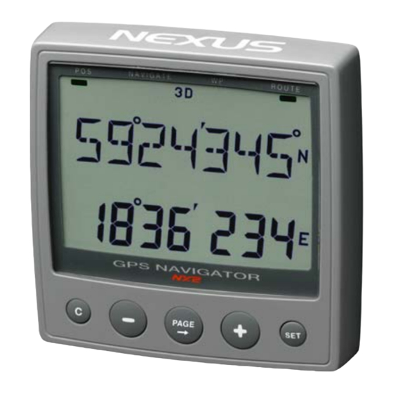
GPS NAVIGATOR GPS STATUS and OPERATION Non of the 2D or 3D flag will be lit during satellite search before navigation can start. When the GPS is tracking satellites, the status symbols 2D or 3D will be displayed at the top of the LCD, as online information If a DGPS receiver is connected and working correctly, the symbol text DGPS will also be displayed. -
Page 21: How To Use The 5 Push Buttons
GPS NAVIGATOR HOW TO USE THE 5 PUSH BUTTONS PAGE BUTTON Is used for selecting main function. Each press on this key will change to a new main function (from left to right). The selected main function will be indicated with the LCD arrow. When editing any value, this key will also move cursor key to edit numbers or text characters with the same functions as above. -
Page 22: Access To Settings
GPS NAVIGATOR ACCESS TO SETTINGS Press minimum 2 secs. on the SET button. 2 sec CLEAR (or ERASE) a WP or value. MAN OVER BOARD To engage Man Over Board, press the two outer keys. & ESCAPE (or ABORT) from edit mode. Press the Cursor key (PAGE) for minimum 2 seconds. - Page 23 GPS NAVIGATOR The display shows ex. "BUOY" no:022. This is the last stored waypoint. Scroll MINUS for other waypoints to EDIT or PLUS to create a new waypoint from a FREE number. Press SET and proceed with the editing. See chapter 6.2.2. regarding editing of WP's. 2.
-
Page 24: Navigation Functions
GPS NAVIGATOR Finding a WP by entering the WP number. If we use the same example as before, there are two ways of moving the cursor to the three digit position (no:nnn). Repeated press on the PAGE button until the left hand digit is flashing. -
Page 25: Pos
GPS NAVIGATOR Access levels and summary of the POS functions. "FIRST SHOWN" POSITION and ALTITUDE, ch. 6.1.1. "Press DOWN" DATE and TIME (local or UTC), ch.6.1 .2. "Press DOWN" BATTERY VOLTAGE (inside the instrument), ch. 6.1.3. "Press DOWN" SATELLITE STATUS and SIGNAL to NOISE, ch. -
Page 26: Battery Voltage
GPS NAVIGATOR 6.1.3 BATTERY VOLTAGE The battery voltage is measured inside the instrument and will differ from the NEXUS Multi Control instrument, where the battery voltage is measured in the Server. 6.1.4 SATELLITE STATUS and SIGNAL to NOISE. HDOP (Horizontal Dilution Of Precision) has normally a low value. If... -
Page 27: Mark Wp
GPS NAVIGATOR Note! This page is only accessible when the NX2 GPS Navigator is in MASTER or SLAVE mode. Not accessible when operating as a REPEATER. See 7.7. Access levels and summary of the WP functions "FIRST SHOWN" MARK WP (Marks a waypoint from pre sent position), chapter 6.2.1. -
Page 28: Copy Wp
GPS NAVIGATOR Press SET and the text FREE is displayed with the WP number flashing. Accept this free WP by pressing the SET. Note! When editing an "old" WP you may search for it by scrolling through the numbers with PLUS or MINUS button. You may also use the GENERAL WAYPOINT SEARCH, see ch 5.11. -
Page 29: Move Wp
GPS NAVIGATOR Select the TO WP number for the WP block 012-123 Set this WP for example "address" to 200 and press SET DONE! 6.2.4 MOVE WP MOVE WP Is the same as COPY with the difference that it will first copy the selected WP's to the new block position before the original waypoints will be erased. -
Page 30: Nav
GPS NAVIGATOR Access levels and summary of the NAV functions "FIRST SHOWN" COMBI VIEW and X-TRACK ERROR, chapter 6.3.1 "Press MINUS" ETA and TTG (Arrival time or time to go to WP), chapter 6.3.2 "Press MINUS " DRIFT (Tidal and boat drift), chapter 6.3.4. "Press MINUS "... -
Page 31: Wcv And Cts
GPS NAVIGATOR example, the boat is drifting on a bearing 234~ with the speed 0,8 knots. Press SET to set the damping of SET/DRIFT and CTS (please see below). Note! The dampening setting will affect all instruments and is not local, as with boat speed and compass. -
Page 32: Goto Wp
GPS NAVIGATOR 6.3.5 GOTO WP The GOTO WP function is the fastest way of selecting a WP to go to and it is normally accessed by pressing the SET button once wherever you are in the NAV page except in DRIFT (where SET sets the dampening) in the Nav function. -
Page 33: Route
GPS NAVIGATOR ROUTE Note! This page is only accessible when the NX2 GPS Navigator is in MASTER or SLAVE mode. Not accessible when operating as a REPEATER. See 7.7. Access levels and summary of the ROUTE functions "FIRST SHOWN" SAIL PLAN (Create, or edit the sail plan), chapter 6.4.1... - Page 34 GPS NAVIGATOR Normally, WP 000 (current position/present position) is accepted as the "START" WP. Press the PLUS button (LEG 01) and press SET. The last edited WP is displayed flashing. Use the GENERAL WAYPOINT SEARCH, chapter 5.11 for finding the first WP to go to and press SET.
- Page 35 GPS NAVIGATOR Repeat until a maximum of 24 WP's (LEG's) have been included in the SAIL PLAN. Also, make it a habit to always VERIFY the Distance and Rearing for all LEG's in the SAIL PLAN, especially if stored as a ROUTE Important! You will affect the ROUTE if you change the lat/ long position for a waypoint that is used within that route.
-
Page 36: Route Call
GPS NAVIGATOR DELETE A LEG Example; Delete WP 1 27 in LEG 2 without any other effect in the SAIL PLAN Use PLUS and MINUS buttons for scrolling through the different LEG's LEG 2 is first displayed, then distance and bearing; DELETE WP 1 27 in this LEG by pressing both PLUS and MINUS buttons simultaneously at the preferred "LEG"... -
Page 37: Reverse Call
GPS NAVIGATOR 6.4.3 REVERSE CALL At least one ROUTE must have been stored to be able to use this function. The selected ROUTE will be copied to the SAIL PLAN in reverse order. It is ADDED to the SAIL PLAN as in the ROUTE CALL. Press SET, "012 flashing"... - Page 38 GPS NAVIGATOR The first free ROUTE is no 001, press SET and give the route a name by using the PLUS, MINUS and PAGE buttons Press and the number of stored WP's are displayed...
-
Page 39: Settings
GPS NAVIGATOR SETTINGS Enter the SETTINGS by pressing the SET button minimum 2 secs. 2 sec There are seven groups of SETTINGS UNITS ALARMS DGPS NMEA OPTIONS CONFIG RETURN Scroll between the main settings with PLUS or MINUS, press the in any of the main settings to enter the submenu Then select from the submenu with PLUS or MINUS and press SET. -
Page 40: Alarms
Ex. shows alarm value entered, 2.5 NM. Note! The XTE Alarm MUST be in Nautical Mile 7.2.4 start time Set actual start time (within 18 hrs) to be used to trig the NX2 Multi Control start timer. RETURN from ALARM set-up. -
Page 41: Gps Settings
This dampening affects Speed Over Ground and Course Over Ground. 7.3.2 latitude correction Note! This is only possible for older Nexus GPS Antennas that are Nexus network compatible (Art no. 21000 Manual latitude correction from WGS-84 in Nautical 0'205 Miles, Note! Only in 1/1000ths of a minute. -
Page 42: Dgps
GPS NAVIGATOR DGPS This is a special POP UP feature for future differential receivers. NMEA Receive NMEA 0183 waypoints ON/OFF. Send out internal WP's once via the NMEA port. Select an individual WP or a group of WP's. 7.5.1 Select NMEA output. Select NMEA output for the 8 channels Each one of the 8 channels can also be set to -, meaning, no output. -
Page 43: Options
This is a special function for transfer (import) of WP's FROM a NEXUS MASTER GPS Navigator instrument TO a NEXUS repeater instrument, Important! IMPORT can only be done from a NEXUS repeater instrument. You must also select WP-BANK since IMPORT will transfer in blocks of 100 WP's. -
Page 44: Chart Page
You are now able to use the Servers waypoints 1 99 as WP's 300-399. Example 2. Move WP 100 to 200 from NEXUS GPS navigator "A" to NEXUS GPS navigator instrument "B" (into memory position). -instrument the same Do as follows, Set to MASTER in the CONFIG for NEXUS GPS "A". -
Page 45: Config
GPS NAVIGATOR CONFIG MASTER, NEXUS-REPEATER or NMEA-REPEATER. NEXUS POS or NMEA P0S. NMEA input or RTCM input. RETURN from CONFIG setup. Important! Always switch POWER OFF then ON to activate a mode change. MASTER Primary navigation is performed in the MASTER instrument. Only one MASTER instrument is allowed. -
Page 46: Choice Of Position Source
7.7.3 NX2 REPEATER SETUP New CONFIG: NEXUS REPEATER and NEXUS P0S. All additional GPS Navigator instruments (for multiple Nav-stations) must be set as NEXUS REPEATERS. There can be only ONE MASTER in the system. 7.7.4 NMEA REPEATER SETUP New CONFIG: NMEA REPEATER and NMEA POS. -
Page 47: Nmea Data
HDC (Heading Comppass) and BSP (Boat speed) is also sent out on NMEA when available from the NEXUS Network. When used as a NMEA repeater, all data will be retransmitted on to the NEXUS Network. Note! In the CONFIG SETUP there is a choice between NMEA-01i83 and , RTCM Input. - Page 48 GPS NAVIGATOR The following sentences can be selected (in the SETUP in the sending Instrument: Sentence: Contents: No sentence sent Autopilot "B" Bearing, origin to destination Bearing & Distance to Waypoint Geographic position Global Positioning System Fix Data Heading Coarse (True) Minimum Navigation data Minimum Specific GPSI TRANSIT data...
- Page 49 Waypoint. All other Waypoints will be sent out when the SEND- WP function is activated in the SETUP. Waypoint ID's are equal to the true (none banked) WP number in the NEXUS Network (with digits). There is no Waypoint Base Number as in the Server- Unit.
-
Page 50: Special Nmea And Nexus Applications
SPECIAL NMEA AND NEXUS APPLICATIONS In some applications, you might need an EXTRA NMEA input port. This is possible by using the NEXUS Server (with one Multi Control instrument) together with one NEXUS GPS navigator instrument. This CONFIGuration will convert NMEA position to NEXUS Network and the NEXUS GPS Navigator instrument will do the Navigation. - Page 51 GPS NAVIGATOR NMEA INPUT The NEXUS GPS NAVIGATOR input port (normally used as the NMEA 0183 input) can also be set to receive the RTCM 104 messages for the SILVA GPS COMPASS. It is preferable to use 4800 baud on the RTCM data to utilise the NMEA 0183 standard output data specified at this baud-rate.
- Page 52 NEXUS NAVIGATOR's memory. SPECIAL USE TO GET EXTRA WP's. When two or more navigator instruments are connected to the NEXUS Network and if more than one "skipper" or family are using the boat, it is sometimes practical to utilise two completely separate WP bank's.
- Page 53 EXTRA FEATURES WITH SILVA NEXUS NETWORK Integrate the navigator with the NEXUS Multi Control and Server by adding compass and speed transducers. You will then get compass heading, boat speed, drift and tidal data (its speed and direction).
-
Page 54: Fault Finding
Cables for damage. Faulty contact in connectors. Connector corrosion caused by poor protection. Short circuit on the NEXUS Network. The following error messages can appear on the display: Some errors are made by improper connections or when calling for unconnected functions (missing transducers). -
Page 55: Technical Data
GPS NAVIGATOR 11 TECHNICAL DATA Dimensions: 113 x 113 x 23 mm Data cable: 8 m. Battery cable 3 m. Battery voltage: Mm. 6.0 V, max. 16.5 V. Power consumption: Without light 0,1 W, With light 0,8 W. Temperature range: Operation -20C to +70C. -
Page 56: Maintenance
GPS NAVIGATOR 12 MAINTENANCE Clean the instrument with mild soap solution only Do not use high-pressure washing equipment! It is advisable to remove the instrument during long cold periods. Put silicon grease on each contact. Check terminals and use wire protection. 13 WARRANTY SILVA SWEDEN AB gives a two year warranty against manufacturing faults or faulty components. -
Page 57: Abbreviations
GPS NAVIGATOR 14 ABBREVIATIONS 2-dimensional navigation 3-dimensional navigation Altitude Acquisition Bearing origin destination (the FROM WP) Bearing Bearing To Waypoint Course Over Ground Correction of LATILON from WG584 Course To Steer DGPS Differential GPS Department of Defence Distance To Waypoint EDIT Programme /enter or alter a value or a name Estimated Time of Arrival... -
Page 58: Specifications
Waypoints to PC-file or to Server and/or to the NX2 GPS. The interface is sPLUSplied with a cable for connection from PC to the Server or NX2 instruments and/or the NX2 GPS. A 9-pole D-sub... -
Page 59: Optional Accessories
GPS NAVIGATOR 16 Optional Accessories Below find a selection of optional accessories available. Please contact your local NX2 dealer for more information. NX2 Completes 22118-3 Multi Control instrument and Server, 8m cable 22118-2 Multi Control and Server with Speed Log and depth transducer, 8m cable... - Page 60 Multi XL instrument, 4m cable (RCI or Multi Center needed to control Multi XL) 21684-1 Multi XL Set, Multi XL instrument and Remote Control instrument 69995 Mast bracket XL, in aluminium for Multi XL and Nexus / Star 110x110mm instr. NX2 GPS 22118-6 GPS Navigator, with GPS Antenna, 8+10m cable...
-
Page 61: Abbreviations
GPS NAVIGATOR 17 Abbreviations Boat Speed Bearing To Waypoint Celsius Fahrenheit KiloMetre KnoTS Miles per Hour Liquid Crystal Display RETurn Speed Over Ground TRiP Minus Plus... -
Page 62: Warranty
GPS NAVIGATOR WARRANTY GENERAL All our products are designed and built to comply to the highest class industry standards. If the products are correctly installed, maintained and operated, as described in the installation and operation manual, they will provide long and reliable service. Our international Network of distributors can provide you with the information and assistance you may require virtually anywhere in the world. - Page 63 GPS NAVIGATOR File id: WARRANTY CARD TO BE RETURNED TO YOUR NATIONAL DISTRIBUTOR OWNER: Name: Street : City/Zip Code : Country: Product name: Serial number: Date of purchase: _______________Date installed ________________ Dealers stamp: Tick here if you do not wish to receive news about future products...
- Page 64 GPS NAVIGATOR Copyright ©: Nexus Marine AB Kuskvägen 4, 191 62 Sollentuna, Sweden Tel: +46 -(0) 8 – 506 939 00. Fax: +46 -(0) 8 -506 939 01 www.nexusmarine.se...