Table of Contents
Advertisement
Quick Links
Advertisement
Table of Contents

Related Manuals for LevelOne PLI-3410


Summary of Contents for LevelOne PLI-3410
-
Page 1: User Manual
LevelOne PLI-3410 200Mbps HomePlug AV Wireless Combo Adapter User Manual V1.0... -
Page 2: Safety Warnings
Safety Warnings 1. Do not use the adapter in high humidity or high temperature environment. 2. Do not open or repair the case yourself. 3. Avoid using this product and all its accessories outdoor. 4. Place the adapter on a stable surface. 5. -
Page 3: Table Of Contents
Table of Contents CHAPTER 1: PRODUCT ................................4 Introduction ..................................4 Features ....................................6 Specifications ..................................7 CHAPTER 2: INSTALLING THE ADAPTER ..........................8 Language Setting ................................8 Package Content ................................. 8 Device Overview ................................10 Hardware Installation ............................... 12 Connecting the HomePlug Adapter .......................... -
Page 4: Chapter 1: Product
Just plug PLI-3410 into any wall power socket, and you can easily set up a secure wireless network by pressing the Wi -Fi Protected Setup (WPS) button. - Page 5 • Quality of Service (QoS) over PowerLine Quality of Service control guarantees the transmission quality by automatically prioritizing data. PLI-3410 automatically recognizes the bandwidth needs of voice and video applications. QoS prioritizes the data to guarantee optimal transmission quality. TV and video images are received and displayed with absolute smoothness.
-
Page 6: Features
Features • Provides physical layer data rate of up to 200Mbps over existing in-home power lines • Extended wireless coverage of up to 3 times the range of 802.11g products • WPS (Wi-Fi Protected Setup) for easy setup • Auto channel select •... -
Page 7: Specifications
Specifications Protocol TDMA, CSMA/CA Standard Ethernet specification: IEEE 802.3, IEEE 802.3x, IEEE 802.3u, Auto MDI/MDIX Transmission Speed 200Mbps Modulation Supports OFDM - 1155 carriers,1024 / 256 / 64 / 16 / 8 QAM, QPSK, BPSK and ROBO Frequency Band 2MHz ~ 30MHz Security 128-bit AES Link Encryption with key management for secure power line communications... -
Page 8: Chapter 2: Installing The Adapter
Chapter 2: Installing the Adapter Language Setting Package Content • PLI-3410 200Mbps HomePlug AV Wireless Combo Adapter • Quick Start Guide • CD User Manual • Ethernet Cable... -
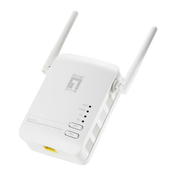
Page 10: Device Overview
Device Overview WLAN LED Clip Socket Power LED PLC LED ETH LED WPS Button SYNC Button Ethernet Port Reset Button Power Plug The Description of each labeled part is described in the table below. WLAN LED Lit green when the wireless function is enabled. Blinking when data is transmitted or received via WLAN. - Page 11 Reset Button Press this button 1~3 second(s) to reset device to factory default settings. Ethernet Port Connect the HomePlug AV device with an Ethernet device (e.g. computer, router, hub/switch, IP pone, IPTV set-top-box, gaming consoles…), using the RJ-45 Ethernet cable included. Power Plug / AC Plug into an AC outlet for power supply and to build a PowerLine network Power Cord...
-
Page 12: Hardware Installation
Hardware Installation Refer to the following diagrams and instructions to install the clip with PLI-3410: Example 1: EU clip • Please check the lock instruction on your clip. • If you got the “Triangle Lock”, refer to right diagram. - Page 13 Example 2: UK clip • Please check the lock instruction on your clip. • If you got the “Circle Lock”, refer to right diagram.
-
Page 14: Connecting The Homeplug Adapter
Plug PLI-3410 into the wall outlet/socket. LAN & Wireless Connection Connect the supplied RJ-45 Ethernet cable to the Ethernet port on PLI-3410 and the other side to the device’s Ethernet interface. You can enable wireless function to connect to the Wi-Fi devices through WPS configuration... -
Page 15: Wps Configuration
WPS configuration. Keep pushing the WPS button of PLI-3410. Then push WPS button of your wireless IP device, and the Wi-Fi protection will be set up automatically. Likewise, do same steps for other wireless devices having WPS button. Example: Wireless IP Devices... -
Page 16: Networking Setup
Networking Setup Refer to the following steps: 1. Connect a network cable to the bridge and then plug PLI-3410 into a power socket. 2. Then connect PLI-3410 to a laptop, modem, router or a set-top-box. 3. Create a secure network by simply pushing the SYNC button for 1~3 seconds. -
Page 17: Quick Start (Setup Powerline Network)
Quick Start (Setup PowerLine Network) Push Button usage Sync Button is used to add a HomePlug device to a PowerLine network or enable it to join a network by pressing the Sync Button of the device to turn it into Broadcast state or Join state. There are 3 types of Sync Button trigger states: 1. - Page 18 Example: 1. Press the Sync Button of device A for more than 10 seconds to make sure that it is detached completely from any possible network group. 2. Press the Sync Button of device B or C of the BC network group for 1~3 seconds to turn it into Broadcast State, you should find the Power LED blinks steadily signifying it is in Broadcast state.
- Page 19 PowerLine Network Illustration...
-
Page 20: Chapter 3: Basic Network Installation
Chapter 3: Basic Network Installation The HomePlug adapter can be configured through your web browser. A web browser is included as a standard application in the following operating systems: Linux, Mac OS, Windows 98/NT/2000/XP/ Me/Vista, etc. The product provides an easy and user-friendly interface for configuration. Please check your PC network components. -
Page 21: Network Configuration
Network Configuration Configuring PC in Windows Vista / 7 1. Go to Start. Click on Network. 2. Then click on Network and Sharing Center at the top bar. 3. When the Network and Sharing Center window pops up, select and click on Manage network connections on the left window column. - Page 22 5. Select Internet Protocol Version 4 (TCP/IPv4) then click Properties. 6. In the TCP/IPv4 properties window, click Use the following IP address and Use the following DNS server address radio buttons. Then click OK to exit the setting. 7. Click OK again in the Local Area Connection Properties window to apply the new configuration.
- Page 23 Configuring PC in Windows XP 1. Go to Start > Control Panel (in Classic View). In the Control Panel, double-click on Network Connections 2. Double-click Local Area Connection. 3. In the Local Area Connection Status window, click Properties. 4. Select Internet Protocol (TCP/IP) and click Properties.
-
Page 24: Factory Default Settings
Factory Default Settings Before configuring your adapter, you need to know the following default settings. Web Interface (Username and Password) Username: admin Password: admin The default username and password are “admin” and “admin” respectively. Group Name: HomePlugAV Device LAN IP settings IP Address: 192.168.1.1 Subnet Mask: 255.255.255.0 DHCP server... -
Page 25: Configuring With Your Web Browser
192.168.1.1, and click “Go”. A user name and password window prompt will appear. The default username and password are “admin” and “admin”. Congratulations! You are now successfully logon to the PLI-3410 200Mbps HomePlug AV Wireless Combo Adapter! If the authentication succeeds, the homepage will appear on the screen. -
Page 26: Chapter 3: Utility Installation
Chapter 3: Utility Installation The utility can be used on the following Windows platform: Windows 2000/XP/Vista/7. 1. Place the LevelOne PLI-3410 HomePlug AV 200 Utility auto-installation CD into your CD- ROM/DVD-ROM drive. 2. Click on Utility for Easy Installation to install the utility. -
Page 27: Utility Installation
Utility Installation 1. After clicking on Utility for Easy Installation, the installation wizard will appear. Click Next. - Page 28 In addition, you can also choose to install PLI-3410 200Mbps HomePlug AV Wireless Combo Adapter Utility only for yourself or for all the users who share your PC. When all necessary items are properly selected, press Next to proceed.
- Page 30 4. While the utility installation is in progress, the system will automatically prompt you to install the WinPcap program in a separate window pop-up. Install this program in order for the utility to work well. 5. While the utility installation is in progress, the system will automatically prompt you to install the WinPcap program in a separate window pop-up.
- Page 31 6. When the WinPcap installation window pops up, click Next to proceed with the installation. 7. Click on Next to proceed to the next step.
- Page 32 8. Read through the license agreement then click on I Agree button to accept the agreement term. 9. If you want the WinPcap driver run automatically when booting, please tick Automatically start the WinPcap driver at boot time. Then click on install to continue the installation.
- Page 33 10. When the WinPcap installation is done, click on Finish to close the window.
- Page 34 11. When the WinPcap installation is done, you will have also completed the LevelOne PLI-3410 200Mbps HomePlug AV Wireless Combo Adapter Utility installation as well. You may now click on the close button of the Utility installation window to finish the process.
-
Page 35: Utility Configuration
Accessing LevelOne PLI-3410 HomePlug AV 200 Utility Click the icon of PLI-3410 on desktop LevelOne PLI-3410 200Mbps HomePlug AV Wireless Combo Adapter Utility consists of 6 screens accessed through these panel tabs. The 5 panels are Main, Privacy, QoS, Diagnostics and About... -
Page 36: Main Tab
Main Tab The Main Tab screen lists all the PowerLine devices that are connected to the host computer when the utility is running. The top left window panel shows all the local HomePlug AV devices that are connected to the computer’s NIC (Network Interface Card). Normally, only one device will be seen on the list. - Page 37 detail information on password setup, please refer to section on Password Setup Instruction. Each device comes with a unique password and it can be found at the back of the device itself. Quality: Display the overall quality of the data transmission rate. When the transmission rate is good, the number of line appear will increase.
- Page 38 1. To enter a password for a specific device, select the device and click on the Enter Password button at the bottom of the lower panel to call up the Set Device Password dialog box. 2. Then type in the password in the blank provided and press OK. Note: The password of each HomePlug device can be found at the back of the device.
- Page 39 3. If the password entered is not recognized or unacceptable, an error message box will pop up prompting user to change the password. Click OK then re-enter the password again. 4. If the password entered is correct, you will see that the password will be displayed next to the device.
-
Page 40: Privacy Tab
Privacy Tab Privacy Tab allows user the convenience to manage the security of the private PowerLine network. In addition, user can also utilize this feature to add a new HomePlug device to the private network instead of manually adding the device using its SYNC button. In order to add devices to the network through the utility GUI, Private Network Name of each device is required to be the same with the local device. -
Page 41: Qos Tab
QoS Tab This function allows user the flexibility to manage the bandwidth usage for each HomePlug device. The higher the QoS priority the more bandwidth usage is allocated to that particular device. To set the QoS priority of each device: 1. -
Page 42: Diagnostic Tab
Diagnostic Tab The Diagnostics Tab screen shows System information and a history of all remote devices seen over a period of time. This screen is available for OEM/ODM Customization. The Upper panel shows technical data concerning software and hardware present on the host computer which were used for communication via HomePlug device on the PowerLine network. - Page 43 • Transfer rate • Device Last Known Network name • Vendor name • Date device last seen on the network • MAC Firmware version The diagnostics information displayed may be saved as a text file for later use, or it can be printed for reference.
-
Page 44: About Tab
About Tab The About screen shows the software version. Under the Preferences panel, user can check the AutoScan box to turn on the Auto Scan function or check off the box to turn off the Auto Scan function. -
Page 45: Chapter 4: Ui Configuration
Chapter 4: UI Configuration Once you have logged on to your adapter GUI via your web browser, you can begin to configure the device according to your needs. On the configuration homepage, the left navigation pane provides the links to different setup pages. ♣... -
Page 46: Status
Status System Information Model Name: Displays the model name. Firmware Version: Displays the firmware version for this device. System Up Time: Records system up-time. LAN IP Address: The current IP on this device. LAN Netmask: The current subnet mask on this device. Note: Click the LAN IP Address or LAN Netmask link to change the settings. -
Page 47: Statistic
Connected Device: Displays the number of the remote power line device(s). Note: Click the Power Line Service or Connected Device link to display the power line information. Statistic Memory Memory total: Displays the total memory size of the device (in bytes). Memory left: Displays the amount of memory left (in bytes). -
Page 48: Internet Setting
Internet Setting IP Address: Enter the preferred IP address. Default is 192.168.1.1. Subnet Mask: Enter the preferred subnet mask. Default is 255.255.255.0. LAN2: This function enables the creation of multiple virtual IP interfaces for this device. It helps to connect two or more local networks to the ISP or remote node. In this case, an internal device is not required. - Page 49 DHCP Server DHCP allows networked devices to obtain information on the parameters of IP, Netmask, and so forth through the Ethernet Address of the device. DHCP Type: To configure the device’s DHCP Server, select Server from the DHCP Type drop- down menu and you can then configure parameters of the DHCP Server.
-
Page 50: Wireless Settings
Wireless Settings When you click this item, the column will expand to display the sub-items that will allow you to configure your wireless settings. Basic, Security, Advanced, WPS and Station List The function of each configuration sub-item is described in the following sections. Basic Wireless Settings Wireless Network WLAN Service: Default setting is Enable. - Page 51 a wireless client searches for a network, the device can be discovered and recognized. Default setting is Disable. ♣ Enable: When enabled, the SSID is broadcast for wireless users to use. ♣ Disable: When disabled, prevents the SSID broadcast from being seen by wireless users. Frequency Channel: Select the wireless connection ID channel that you would like to use.
- Page 52 Bridge Mode WDS Mode: Select Bridge Mode from the drop-down menu. In this case, AP adapter acts as a wireless bridge and will not respond to wireless requests. Phy Mode: Select the appropriate mode from the drop-down menu. There are 4 options: CCK, OFDM, HTMIX and GREENFIELD.
-
Page 53: Wireless Security/Encryption Settings
Wireless Security/Encryption Settings Security Mode: You can disable or enable the wireless security function using WEP or WPA for wireless network protection. The default mode of wireless security is disabled. Please refer to the Security Mode section for detail description. Access Policy Policy: Select from the drop-down menu to choose whether the entered MAC Address should be allowed to pass (Allow) or to be blocked (Reject). - Page 54 Security Mode WEP OPEN / WEP SHARED / WEP AUTO Security Mode: Select WEP OPEN, WEP SHARED or WEP AUTO from the drop-down menu. Wire Equivalence Protection (WEP) Default Key: Select the encryption key ID. WEP Keys (1~4): Enter the key to encrypt wireless data. To allow encrypted data transmission, the WEP Encryption Key values on all wireless stations must be the same as the device.
- Page 55 WPA-PSK / WPA2-PSK / WPAPSK/WPA2PSK mix mode Security Mode: Select WPA-PSK or WPA2-PSK from the drop-down menu. WPA Algorithms: There are 3 types of the TKIP, AES & TKIPAES (not available in WPA-PSK mode). Pass Phrase: Enter a pass phrase to access the network. It can be a password like “12345678” or a pass phrase, from 8 to 63 case-sensitive characters.
-
Page 56: Advanced Wireless Settings
Advanced Wireless Settings Advanced Settings TX Power: TX Power measurement that enhances the wireless transmission signal strength. You can adjust this power level from minimum (0) to maximum (100). Default is 100. Tx Burst: This feature is used to activate the transmitted time slot to increase transmission throughput. -
Page 57: Wi-Fi Protected Setup
Wi-Fi Protected Setup WPS feature is designed to ease setup of security enabled WiFi networks in small offices or home. It supports methods to you to set a network and enable security by entering a PIN or pushing a button. WPS Config WPS: Default setting is Enable. - Page 58 WPS Summary WPS Current Status: Displays the WPS status. WPS Configured: Displays the current WPS configuration status WPS SSID: Displays the WPS network name. WPS Authentication Mode: Displays the authentication mode for WPS. WPS Encryption Type: Displays the encryption type for WPS. WPS Default Key Index: Displays the Default Key Index.
-
Page 59: Station List
Station List The Station List displays the Wireless Network information. Wireless Network MAC Address: The Media Access Control (MAC) addresses for each device on your WLAN. Aid: The association ID. PSM: The power save mode. MimoPS: The MIMO power save mode. MIMO, Multiple-input and multiple-output, is the use of multiple antennas at both the transmitter and receiver to improve communication performance. - Page 60 Power Line Settings Status Local Device Model: Displays the model name for the local power line device. Firmware: Displays the version number of firmware on the local power line device. MAC Address: Displays the MAC address of the local power line device. When you have successfully synchronized two HomePlug AV adapters through the PowerLine, the information of both adapters will display on the Power Line Status screen.
- Page 61 Security Security Settings New Network Password (Name): Enter the new network password (name) to apply to the local HomePlug adapter. This allows the HomePlug adapters that have the same network password in the PowerLine network to communicate with each other. Click Apply to confirm the setting.
- Page 62 default settings when you click on Apply button. Note: When there is no QoS policy on the device, a warming message will pop-up as below after clicking Apply. QoS example: The above illustration is an example for QoS topology, commonly in the home and small office environment.
- Page 63 Enter “ipconfig/all” here 00:11:2F:23:23:42 Your MAC address 3. Go back to Power Line QoS Settings screen, enter you network card MAC address and choose the priority. Click Add button to add this new rule. You will see the new address(s) displayed in the QoS Policy table.
- Page 64 Note: Do NOT perform any more actions in QoS setting process. 6. Once the setting is complete, you will be returned to the Power Line QoS Settings page.
-
Page 65: Administration
Administration System Management Administrator Settings Account: You are allowed to set your own account name. Default is admin. Password: You are allowed to set your own password. Default is admin. Click Apply to save the changes. -
Page 66: Firmware Upgrade
Firmware Upgrade Upgrading the newly improved version of the firmware allows you to get the advantage to use newly integrated features. Update Firmware Location: Click on Browse to select the new firmware image file you have downloaded to your PC. Once the correct file is selected, click Apply to update the firmware to your device. -
Page 67: Settings Management
Settings Management These functions allow you to save a backup of the current configuration of your device to a defined location on your PC, to restore a previously saved configuration, or to restart your device with the factory default settings. This is useful if you wish to experiment with different settings, knowing that you have a backup in hand in case any mistakes occur. -
Page 68: Chapter 5: Troubleshooting
Chapter 5: Troubleshooting If your device is not functioning properly, please refer to the suggested solutions provided in this chapter. If your problems persist or the suggested solutions do not meet your needs, please kindly contact your service provider for support. Problems with the device Problem Suggested Solution... -
Page 69: Appendix: Product Support & Contact
This may due to the accidental change of the device password. My HomePlug device is unable to detect my other Access the HomePlug AV web interface and select Power Line HomePlug device. Settings > Privacy. Fill in the password (case sensitive) in the blank.