
Related Manuals for Tokyo Hy-Power HL-350VDX


Summary of Contents for Tokyo Hy-Power HL-350VDX
- Page 1 User’s Manual 144MHz Band 330W Power Amplifier Model HL-350V TOKYO HY-POWER LABS., INC.
- Page 2 Introduction The HL-350VDX is a 144MHz Band Linear Power Amplifier with the maximum output power of 300W (nominal, 330W max.), designed with Tokyo Hy-Power’s accumulated VHF technologies. This is a completely solid-state amplifier capable of handling all transmission modes. There are built in such new functions as an automatic VSWR meter, a new type DC-operated line-flow fan and a GaAs FET RX Pre-amp with a selectable RX gain.
- Page 3 Specifications Frequency Band : 144MHz Band (available for 144-148 MHz) Mode: FM, SSB and CW RF Output Power: 300W nominal (330W max.) RF Input Power: 10/25/50 W (manually selectable) DC Power Supply: 13.8 VDC Power Consumption: 42A max. (at 250W output) Input/Output Impedance: 50Ω...
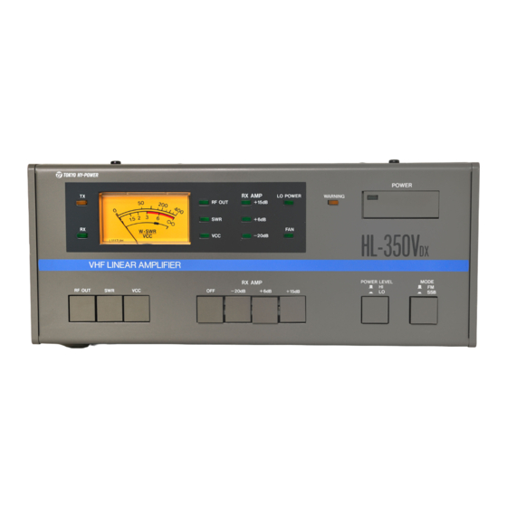
- Page 4 Explanation of Features <FRONT PANEL> ‚ P POWER (MAIN DC POWER SUPPLY SWITCH): A power switch for the TX amp unit. With the first push, the switch will be locked, turning the power ON. With the second push, the knob will be released to turn the power OFF.
- Page 5 starts to run at its full speed. When the heat sink temperature exceeds 70• Ž to a long continuous transmission or any other reasons, the built-in thermo-sensor will halt the transmission automatically. In that case, do not turn OFF 1 POWER SWITCH. This is because the fan has to be kept running in order to cool down the heat sink.
- Page 6 readings. ‚ P ‚ Q RX AMP OFF/-20dB/+6dB/+15dB (SELECTION SWITCH): Selects the gain of the RX pre-amp. Select the proper gain so that the signal can be copied most clearly. ‚ P ‚ R POWER LEVEL HI/LO (SELECTION SWITCH): At 10W and 25W inputs, the power level can be switched to either HI or LO. At the LO mode, the output power becomes approx.
- Page 7 <REAR PANEL> Red Black ‚ P ‚ T 13.8VDC (POWER SUPPLY TERMINAL): Use the included power supply cable for the connection with a stabilized DC power supply. Connect the red wire to + and black wire to - . Make sure to use a power supply with a capacity of 50A minimum. ‚...
- Page 8 REMOTE (REMOTE CONTROLLER JACK): With the use of the optional external remote head (Model No. HRC-60), the following functions can be remotely controlled: 1) Turning ON/OFF of POWER (DC power), 2) Turning ON/OFF of RX AMP (RX pre-amp), 3) Switching of HI/LO (TX output power level), and 4) Resetting of WARNING CIRCUIT shut down.
- Page 9 *Wiring Details for REMOTE TERMINAL (remote controller connection jack) are as follows: (Don’t connect ACC CONNECTOR here!) When viewed from the outside of the rear panel•¨ Terminal No. Noun Connection Details ‡ @ RX SW This is connected to the switch of RX pre-amp. When 13.8VDC is applied, the RX pre-amp will be turned ON.
- Page 10 CONNECTION Optional Remote Controller (HRC-60) 13.8VDC/50A Power Supply PTT (Hard Key) Cable red(+) 50Ω Coaxial Cable (Use included cable.) black(-) Power Supply Lead (Use included cables.) *Our HP-450 144MHz Band (63A DC power supply) is Transceiver available as option. black 50Ω...
- Page 11 b) Pull off the center wire. Center Conductor Braid c) Peel off the sheath of the center wire tip. 2mm (1/12 inch) Sheath ‡ A Disassemble DIN Plug: a) Remove the plastic case from the plug. Use a screw driver to raise this thin part. b) Remove cylindrical metallic parts.
- Page 12 Solder to DIN Plug. (When viewed from the rear end.) ‡ E + DC Solder the tip of the center conductor. ‡ F S H O R T ‡ B G ND Solder the braid to the GND pin. *Note: If the transceiver externally supplies no voltage (0V, =TX Gnd.) during the TX, solder the center conductor to Pin ‡...
- Page 13 TX OPERATION (1) Before keying the radio, set the switches on the front and rear panel as follows: ‡ @ POWER (Power Switch) → OFF ‡ A RX AMP (RX Pre-Amp Switch) → OFF ‡ B METER SELECT SWITCH → VCC ‡...
- Page 14 Cautions 1. Power Supply: (1) This amplifier is designed to work from 13.8VDC power supply. Never connect to an AC line such as 115/120/220/240 VAC. Such inadvertent connection will kill the amplifier. (2) Higher supply voltage above 14VDC will lead to damage of the amp. Keep the power supply at the designed voltage of 13.8VDC.
- Page 15 4. Transceiver: If this amplifier is driven with more than 50W, final power transistors may be killed due to over-drive. Check if the output power of the driving transceiver is within the designed input power ranges of this amplifier. 5. Access To Internal Parts: This amplifier is carefully assembled and adjusted with sophisticated RF measurement instruments.
- Page 16 Outline of Each Unit 1. TX Unit: Part of the output power of the transceiver is detected at J101, so that the carrier controlled solid-state switching circuit turns ON/OFF IC201 (NJM2072D) and Q202 (2SC1959Y), activating the TX/RX change-over relay. The RF signal inputted from J101 is amplified from 10W to 80W through DRIVER AMP Q1 (MRF247), and further amplified to the designed power of 250W to330W through MAIN AMP Q1•...
- Page 17 70• Ž . The HL-350VDX utilizes an indirect DC main power control circuit where the power is turned ON/OFF by the Power Relays (RL6 and RL7). Diode D24...
- Page 18 If 24VDC is inadvertently connected, Zener Diode (05Z16A) will not turn ON Relay Controlling Transistor Q203 (2SC3419Y) preventing Power Relays (RL6 and RL7) from being activated.
- Page 20 Trouble Shooting Following symptoms are not a sign of trouble. Please refer to the treatment column for correction. If you still cannot fix the situation, then please call our distributor or contact us for further technical advice. Symptoms Causes Treatments DC Power won’t 1) Power connector Properly connect it again.
- Page 21 MAJOR PARTS LIST Marks Q’ty Part No. / Description D2,D5,D7,D8,D18,D19, 1S2076A, silicon diode D25,D26,D27,D28, D201,D203,D204,D205, D206,D209• ` 216,D219 1K60, germanium diode D9,D15,D16,D22,D23 1N4002, silicon diode 1N4002, silicon diode D6,D20,D21,D220 1SS97, shottky barrier diode D217 05AZ16, zener diode D218 CR02AM, thyristor D14,D202 HZ5A1, zener diode D10,D11,D12,D13...
- Page 22 SSSP12L1118VH G7018699M, 2-cir. 3-cont. slide S/W VR1,VR2,VR202 1K ohms, semi-fixed variable resistors, horizontal VR203,VR203,VR205 10K ohms, semi-fixed variable resistors, horizontal VR201 100K ohms, semi-fixed variable resistors, horizontal 500 ohms, semi-fixed variable resistors, vertical ECVIZW10X53T 10PF/250VDC, trimmer capacitor, ceramic ECVIZW20X53T 20PF/250VDC, trimmer capacitor, ceramic 22222-808-11229 22PF/250VDC, film trimmer capacitor...
- Page 23 Extension Cable for HRC-60, HRC-6L (4m long, Sold separately): 8-Pin DIN Plug ÿ 4m long cable ÿ 8-Pin DIN Jack TOKYO HY-POWER LABS., INC. TOKYO HY-POWER LABS., INC. - (USA Office) 1-1 Hatanaka 3-chome, Niiza, 6046 FM 2920 Rd...