Carrier 48ES Installation Instructions Manual
Single-packaged gas furnace/air conditioner system with puron (r-410a) refrigerant single- and three-phase units
Hide thumbs
Also See for 48ES:
- Owner's information manual (10 pages) ,
- Installation instructions manual (36 pages)
Table of Contents
Advertisement
48ES
Single- -Packaged Gas Furnace/Air Conditioner
System with PuronR (R- -410A) Refrigerant
Single- - And Three- -Phase Units Sizes 018- -060
NOTE: Read the entire instruction manual before starting the
installation.
NOTE: Installer: Make sure the Owner's Manual and Service
Instructions are left with the unit after installation.
TABLE OF CONTENTS
. . . . . . . . . . . . . . . . . . . . . . . . . . . . . . . . . .
. . . . . . . . . . . . . . . . . . . . . . . . . . . . . . . . .
. . . . . . . . . . . . . . . . . . . . . . . . . . . . . . . . . . .
. . . . . . . . . . . . . . . . . . . . . . . . . . . . . . . .
. . . . . . . . . . . . . . . . . . . . . . . . . . . . . .
. . . . . . . . . . . . . . . . . . . . . . . . . . . . . . . . . . . . .
. . . . . . . . . . . . . . . . . . . . . . . . . . . . . . . . . . . .
. . . . . . . . . . . . . . . . . . . . . . . . . . . . . . . . .
. . . . . . . . . . . . . . . . . . . . . . . . . . .
. . . . . . . . . . . . . . . . . . . . . . . . . . . . . . . .
. . . . . . . . . . . . . . . . . . . . . . . . . . . . . . . .
. . . . . . . . . . . . . . . . . . . . . . . . . . . . . . . . . . . . .
. . . . . . . . . . . . . . . . . . . . . . . . . . .
. . . . . . . . . . . . . . . . . . . . . . . . . . . . . . . . . .
. . . . . . . . . . . . . . . . . . . . . . . . . . . . . . . . .
. . . . . . . . . . . . . . . . . . . . . . . . . . . .
. . . . . . . . . . . . . . . . . . . . . . . . . . . . . . . . . .
. . . . . . . . . . . . . . . . . . . . . . . . . .
. . . . . . . . . . . . . . . . . . . . . . . . . . . . . . .
. . . . . . . . . . . . . . . . . . . . . . . . . . . . . . . . . . . .
. . . . . . . . . . . . . . . . . . . . . . . . . .
. . . . . . . . . . . . . . . . . . . . . . . . . . . . . . .
. . . . . . . . . . . . . . . . . . . . . . . . . . . . . . .
. . . . . . . . . . . . . . . . . . . . . . . . . . . .
. . . . . . . . . . . . . . . . . . . . . . . . . . . . . . . .
. . . . . . . . . . . . . . . . . . . . . . . . . . . . . . . .
. . . . . . . . . . . . . . . . . . . . . . . . . . . . . . .
. . . . . . . . . . . . . . . . . . . . . . . . . . . . . . . . . . . . .
. . . . . . . . . . . . . . . . . . . . . . . . . . .
Installation Instructions
. . . . . . . . . . . . . . . . . . . . . . . .
. . . . . . . . . . . . . . . .
. . . . . . . . . . . . . . . . . . . . . . . . . .
. . . . . . . . . . . . . . . . . . . . . . .
. . . . . . . . . . . . . . . . . . . . . . .
. . . . . . . . . . . . .
. . . . . . . . . . . . . . . . . . . . . .
. . . . . . . . . . . . . . . . . . . . . . . . .
12- -13
13- -19
. . . . . . . . . . . . . . . . . . . . . . . .
. . . . . . . . . . . . . . .
. . . . . . . . . . . . . . . . . . . . .
. . . . . . . . . . . . . . . . . . . .
. . . . . . . . . . . . . . .
. . . . . . . . . . . . . . .
. . . . . . . . . . .
. . . . . . . . . . . .
. . . . . . . . . . . . . . . . . . . .
23- -26
. . . . . . . . . . . . . . . . . . . . . . . .
Page
1
2
2- -12
2
2
2
2
2
2
2
2
6
6
6
6
8
8
9
9
9- -10
11
11
11
11
12
12
13
13
13
13
Installation and servicing of this equipment can be hazardous due to
14
mechanical and electrical components. Only trained and qualified
14
personnel should install, repair, or service this equipment.
14
Untrained personnel can perform basic maintenance functions such
18
as cleaning and replacing air filters. All other operations must be
18
performed by trained service personnel. When working on this
18
equipment, observe precautions in the literature, on tags, and on
18
labels attached to or shipped with the unit and other safety
18
precautions that may apply.
18
19
Follow all safety codes. Installation must be in compliance with
19
local and national building codes. Wear safety glasses, protective
clothing, and work gloves. Have fire extinguisher available. Read
23
these instructions thoroughly and follow all warnings or cautions
23
included in literature and attached to the unit.
23
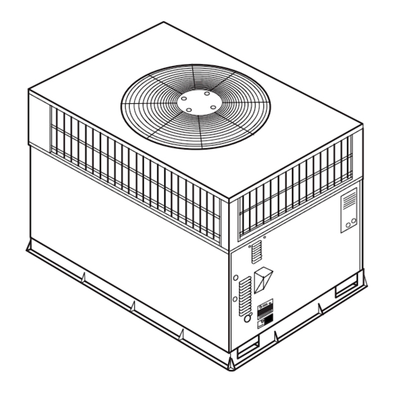
1
Fig. 1 - - Unit 48ES
(Low NOx Model Available)
. . . . . . . . . . . . . . . . . . . . . . . . . . . . . . . . . .
. . . . . . . . . . . . . . . . . . . . . . . . . . . . . . . .
. . . . . . . . . . . . . . . . . . . . . . . . . . . . . . . . . .
. . . . . . . . . . . . . . . . . . . . . . . . . . . . . . . . . .
. . . . . . . . . . . . . . . . . . . .
. . . . . . . . . . . . . . . . . . . . . . . . . . . . . .
. . . . . . . . . . . . . . . . . . . . . . . . . . . . . . . . . . . . .
. . . . . . . . . . . . . . . . . . . . . . . . . . . . .
. . . . . . . . . . . . . . . . . . . . . . . . . . . . . . . .
. . . . . . . . . . . . . . . . . . . . . . . . . . . . .
. . . . . . . . . . . . . . . . . . . . . . . . . . .
SAFETY CONSIDERATIONS
A99338
. . . . . . . . . . . . .
24
24
24
24
. . .
24
25
25
25
25
25
25- -26
27
27
Advertisement
Table of Contents

Related Manuals for Carrier 48ES


Summary of Contents for Carrier 48ES
-
Page 1: Table Of Contents
........Fig. 1 - - Unit 48ES Use of Rigging Bracket . -
Page 2: Introduction
OPENING OPENING INTRODUCTION The 48ES unit (see Fig. 1) is a fully self- -contained, combination Category I gas heating/electric cooling unit designed for outdoor installation (See Fig. 3 and 4 for unit dimensions). All unit sizes have return and discharge openings for both horizontal and 2"... - Page 3 REQUIRED CLEARANCE TO COMBUSTIBLE MATL. REQUIRED CLEARANCE FOR OPERATION AND SERVICING INCHES [mm] (R efer to M aximum O perating C learances ) EVAP. COIL ACCESS SIDE............36.00 [914.0] INCHES [mm] TOP OF UNIT...................14.00 [355.6] POWER ENTRY SIDE..............42.00 [1066.8] DUCT SIDE OF UNIT.................2.00 [50.8] (EXCEPT FOR NEC REQUIREMENTS) UNIT TOP ..................48.00 [1219.2] SIDE OPPOSITE DUCTS ..............14.00 [355.6]...
- Page 4 REQUIRED CLEARANCE TO COMBUSTIBLE MATL. REQUIRED CLEARANCE FOR OPERATION AND SERVICING INCHES [mm] INCHES [mm] EVAP. COIL ACCESS SIDE............36.00 [914.0] TOP OF UNIT...................14.00 [355.6] POWER ENTRY SIDE..............42.00 [1066.8] DUCT SIDE OF UNIT.................2.00 [50.8] (EXCEPT FOR NEC REQUIREMENTS) SIDE OPPOSITE DUCTS ..............14.00 [355.6] UNIT TOP ..................48.00 [1219.2] BOTTOM OF UNIT ................0.50 [12.7] SIDE OPPOSITE DUCTS ..............36.00 [914.0]...
- Page 5 HVAC unit HVAC unit base base Gask eting inner flange* Scre w Scre w Gask eting (NO TE A) (NO TE A) inner flange* *Gask eting *Gask eting outer flange outer flange Wood nailer* Wood nailer* Flashing field Flashing field supplied supplied Roof curb*...
-
Page 6: Provide Clearances
Step 4—Provide Clearances WARNING The required minimum operating and service clearances are shown in Fig. 3 and 4. Adequate combustion, ventilation and condenser air PROPERTY DAMAGE HAZARD must be provided in accordance with section 5.3, Air for Combustion and Ventilation, of the National Fuel Gas Code ANSI Failure to follow this warning could result in personal (American National Standards Institute) Z223.1 or applicable injury/death or property damage. - Page 7 - out Reset (auto) RETURN--- AIR FILTERS†} 20x24x1 24x30x1 24x36x1 Throwaway Size (in.) 508x610x25 (mm) 610x762x25 (mm) 610x914x25 (mm) Table 1—Physical Data Con’t - - Unit 48ES UNIT SIZE 048090 048115 048130 060090 060115 060130 NOMINAL CAPACITY (ton) OPERATING WEIGHT lb OPERATING WEIGHT kg 189.6...
-
Page 8: Connect Condensate Drain
217.7 230.4 Weight Weight Fig. 6 - - 48ES Unit Corner Weights (in Pounds) and Suggested Rigging Step 6—Connect Condensate Drain Step 7—Install Flue Hood The flue assembly is secured and shipped in the return air duct. NOTE: When installing condensate drain connection be sure to Remove duct cover to locate the assembly (See Fig. -
Page 9: Install Gas Piping
2. Remove flue hood from shipping location (inside the return section of the blower compartment- -see Fig. 9 & 10). Re- move the return duct cover to locate the flue hood. Place flue hood assembly over flue panel. Orient screw holes in flue hood with holes in the flue panel. - Page 10 Table 2—Maximum Gas Flow Capacity* NOMINAL INTERNAL LENGTH OF PIPE (FT)† IRON PIPE DIAMETER SIZE (IN.) (IN.) .622 — — .824 1.049 1- - 1/4 1.380 1400 1- - 1/2 1.610 2100 1460 1180 *Capacity of pipe in cu ft of gas per hr for gas pressure of 0.5 psig or less. Pressure drop of 0.5- -in. wc (based on a 0.60 specific gravity gas). Refer to Table, National Fire Protec- tion Association NFPA 54.
-
Page 11: Install Electrical Connections
Step 10—Install Electrical Connections Single phase units: 1. Run the high- -voltage (L1, L2) and ground lead into the WARNING control box. 2. Connect ground lead to chassis ground connection. ELECTRICAL SHOCK HAZARD 3. Locate the black and yellow wires connected to the line side Failure to follow this warning could result in personal injury of the contactor. -
Page 12: Heat Anticipator Setting
PRE- -START- -UP HIGH VOLTAGE WARNING POWER LEADS POWER (SEE UNIT WIRING SUPPLY LABEL) FIRE, EXPLOSION, ELECTRICAL SHOCK HAZARD Failure to follow this warning could result in personal injury or death. FIELD-SUPPLIED FUSED DISCONNECT 1. Follow recognized safety practices and wear protective CONTROL BOX goggles when checking or servicing refrigerant system. -
Page 13: Start- -Up
4. Verify the following conditions: a. Make sure gas line is free of air. Before lighting the unit for the first time, perform the following with the gas valve in the OFF position: NOTE: If the gas supply pipe was not purged before connecting the unit, it will be full of air. -
Page 14: Adjust Gas Input
at 0.65 specific gravity, or propane gas with a heating Observe manifold pressure and proceed as follows to adjust gas value of 2500 Btu/ft at 1.5 specific gravity. input: For elevations above 2000 ft, reduce input 4% for each 1. Remove cover screw over regulator adjustment screw on gas valve. - Page 15 A07230 Fig. 15 - - 208/230- -1- -60 Wiring Diagram...
- Page 16 A07232 Fig. 16 - - 208/230- -3- -60 Wiring Diagram...
- Page 17 A07231 Fig. 17 - - 460- -3- -60 Wiring Diagram...
-
Page 18: Heating Sequence Of Operation
Table 3—Heating Inputs GAS SUPPLY PRESSURE (IN. WC) HEATING INPUT NUMBER OF NUMBER OF MANIFOLD PRESSURE (IN WC) MANIFOLD PRESSURE (IN. WC) Natural{ Propane*{ (BTUH) ORIFICES ORIFICES Natural{ Propane*† 40,000 13.0 13.0 60,000 13.0 13.0 90,000 13.0 13.0 115,000 13.0 13.0 130,000 13.0... -
Page 19: Indoor Airflow And Airflow Adjustments
Airflow can be changed by changing the lead connections of the CAUTION blower motor. All 48ES units are factor wired for low speed except sizes 030 and UNIT DAMAGE HAZARD 048 which are wired for medium speed. Failure to follow this caution may result in unit damage. - Page 20 --- --- --- --- --- --- --- --- --- --- --- --- --- --- Heating Rise 30 --- 60 °C 48ES( ---,N)018040 Watts --- --- --- --- --- --- (17 --- 33) 1064 --- --- --- --- --- --- High Heating Rise °C...
- Page 21 Range F (°C) Speed Watts --- --- --- --- Heating Rise °C Watts 20 --- 50 1195 1155 1100 1028 48ES( ---,N)030040 Medium Heating Rise (11 --- 28) °C Watts 1484 1421 1368 1279 1185 1088 High Heating Rise °C...
- Page 22 High Heating Rise °C * Air delivery values are without air filter and are for dry coil (See Table 15 -- 48ES Wet Coil Pressure Drop table). Factory--shipped heating/cooling speed NA = Not allowed for heating speed Note: Deduct field--supplied air filter pressure drop and wet coil pressure drop to obtain external static pressure available for ducting.
-
Page 23: Maintenance
MAINTENANCE AIR FILTER To ensure continuing high performance and to minimize the IMPORTANT: Never operate the unit without a suitable air filter possibility of premature equipment failure, periodic maintenance in the return- -air duct system. Always replace the filter with the same must be performed on this equipment. -
Page 24: Induced Draft (Combustion Air) Blower
1. Remove the combustion blower wheel and motor assembly OUTDOOR COIL, INDOOR COIL, AND CONDENSATE according to directions in the Combustion- -Air Blower DRAIN PAN section. Inspect the condenser coil, evaporator coil, and condensate drain 2. Remove the 3 screws holding the blower housing to the flue pan at least once each year. -
Page 25: Outdoor Fan
4. If fan needs to be removed, loosen setscrew and slide fan off motor shaft. 5. When replacing fan blade, position blade so that the hub is BLOWER 1/8 in. (3.2 mm) away from the motor end (1/8 in. (3.2 mm) HOUSING of motor shaft will be visible) (See Fig. - Page 26 REFRIGERANT SYSTEM NOTE: Because these switches are attached to refrigeration This information covers the refrigerant system of the 48ES, system under pressure, it is not advisable to remove this device including the compressor oil needed, servicing systems on roofs...
-
Page 27: Troubleshooting
PURON (R- -410A) REFRIGERANT CHARGING TROUBLESHOOTING Refer to unit information plate and charging chart. Some R- -410A Use the Troubleshooting Guides (See Tables 10- -12) if problems refrigerant cylinders contain a dip tube to allow liquid refrigerant occur with these units. to flow from cylinder in upright position. - Page 28 Table 10—Troubleshooting Chart SYMPTOM CAUSE REMEDY Power failure Call power company Fuse blown or circuit breaker tripped Replace fuse or reset circuit breaker Defective contactor, transformer, or high--pressure, Replace component loss--of--charge or low--pressure switch Compressor and condenser fan will not start. Insufficient line voltage Determine cause and correct Incorrect or faulty wiring...
- Page 29 Table 11—Troubleshooting Guide–Heating SYMPTOM CAUSE REMEDY Water in gas line Drain. Install drip leg. No power to furnace Check power supply fuses, wiring or circuit breaker. Check transformer. No 20--v power supply to control circuit NOTE: Some transformers have internal over--current protection that requires a cool--down period to reset.
- Page 30 Catalog No: 48ES---2SI Printed in U.S.A. Edition Date: 04/07 Copyright 2007 Carrier Corp. S 7310 W. Morris St. S Indianapolis, IN 46231 Replaces: 48ES- -1SI Manufacturer reserves the right to change, at any time, specifications and designs without notice and without obligations.