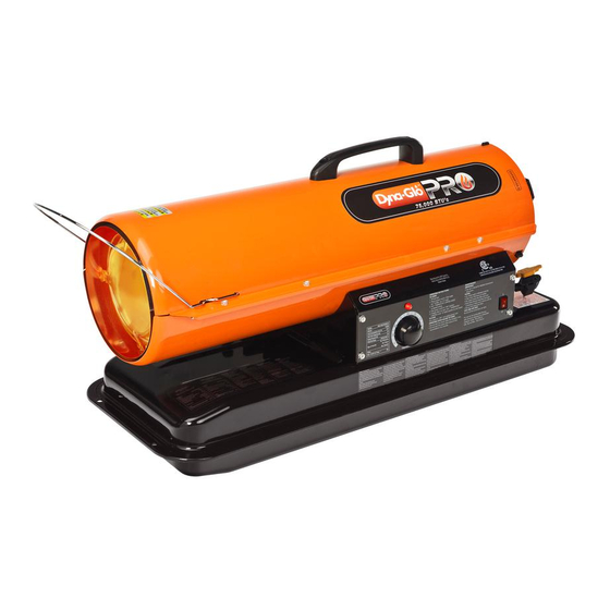
Dyna-Glo KFA50H User's Manual And Operating Instructions
Kerosene portable forced air heaters
Hide thumbs
Also See for KFA50H:
- User's manual and operating instructions (28 pages) ,
- User's manual and operating instructions (27 pages)
Table of Contents
Advertisement
"USER'S MANUAL AND
OPERATING INSTRUCTIONS"
COMPLIES WITH UL733 AND
ANSI A10.10-1998
CAN/CSA/B140.0-03 AND CSA
B140.8-1967
KFA50H, KFA75H, KFA125H, KFA210H
CONSUMER : Retain this manual for future reference.
Questions, problems, missing parts? Before returning to your retailer, call our customer
service department at 877-447-4768 8:30 a.m. - 4:30 pm CST, Monday - Friday.
or email us at customerservice@ghpgroupinc.com
Advertisement
Table of Contents

Related Manuals for Dyna-Glo KFA50H


Summary of Contents for Dyna-Glo KFA50H
-
Page 1: Operating Instructions
ANSI A10.10-1998 CAN/CSA/B140.0-03 AND CSA B140.8-1967 KFA50H, KFA75H, KFA125H, KFA210H CONSUMER : Retain this manual for future reference. Questions, problems, missing parts? Before returning to your retailer, call our customer service department at 877-447-4768 8:30 a.m. - 4:30 pm CST, Monday - Friday. -
Page 2: Risk Of Electric Shock
DANGER: WARNINGS: 1. RISK OF INDOOR AIR POLLUTION! Use this heater only in well ventilated areas. + Carbon monoxide poisoning: Get fresh air at once! 2. RISK OF BURNS/FIRE/EXPLOSION! NEVER NEVER (RISK OF FIRE OR EXPLOSION) NEVER NEVER Minimum Clearances: NEVER NEVER NEVER... - Page 3 Cord Wrap Side Cover (75H Model Only) Pressure Gauge Lamp (75H Model Only) Fuel Gauge Thermostot Knob (75H Model Only) Fuel Cap LED Power/Reset Switch (75H Model Only) Power Cord (Piggy Back,75H Model Only) Figure 1. KFA50H / KFA75H MODELS...
- Page 4 Front Handle Upper Shell Rear Handle Hot Air Outlet Shell Lower Cord Wrap Fuel Gauge Fuel Cap Side Cover Pressure Gauge Lamp Fan Guard Thermostat Knob Room Temp. Display Power Cord LED Power/Reset Switch (Piggy Back) 10” Flat Free Wheel Fuel Drain Bolt Figure 2.
-
Page 5: Unpacking And Assembly
3. UNPACKING AND ASSEMBLY 1. REMOVE THE HEATER AND ALL PACKING MATERIALS FROM THE BOX. (Fig. 4 and 5) KFA50H KFA75H KFA125H KFA210H Figure 4. KFA50H / KFA75H MODELS Cord Wraps Hardware Kit Handle (KFA75H Model Only) HW-KFA1001 Figure 5. KFA125H/KFA210H MODELS... - Page 6 2. ASSEMBLY Screw Frong Guard Handle Tools Required Wedged Portion Slit Hole Cord Wrap Suppotor Side Cover Screw Figure 6. Assembling Handle & Cord Wrap Tools Required...
- Page 7 Screw Front Handle Louver Screw Cap Nut S Rear Handle Hot Air Outlet Cord Wrap Flange Screw Fuel Tank Flange Air Inlet Wheel Support Frame Threaded Axle Wheel Bushing Wheel Cap Nut L Figure 7. Assembling Handle, Wheel and Cord wrap, Louver CAUTION : NOTE : 4.
- Page 8 5. OVERVIEW OF HEATERS DESIGN Fuel System : “Sure Fire Ignition” : The Air System : The Safety System : FUSE TYPE:...
-
Page 9: Fueling Your Heater
Room Temp. Display BTU Control Switch Lamp Push to “HIGH” Lamp Push to “LOW” Thermostat LED Power Thermostat LED Power Control Knob Switch Control Knob Switch (75H Model Only) KFA50H/75H Models KFA125H/210H Models Fan Guard Figure 8. Controls for All Models... - Page 10 NOTICE : The major electrical components of this heater are protected by a safety fuse mounted to the PCB board. If your heater fails to start, check this fuse first and replace as necessary. You should also check your power source to insure that proper voltage and frequency are being supplied to the heater. TO STOP HEATER TO RESTART HEATER Cover...
- Page 11 9. MAINTENANCE WARNING!! : NEVER SERVICE HEATER WHILE IT IS PLUGGED IN OR WHILE HOT! USE ORIGINAL EQUIPMENT REPLACEMENT PARTS. Use of third party or other alternate components will void warranty and may cause unsafe operating conditions. Screw Upper Shell A.) FUEL TANK Air Intake Filter B.) AIR INTAKE FILTER...
- Page 12 E.) NOZZLE Combustion Chamber Screw Ignitor Wire Spark Plug Nozzle Adaptor Burner Head Fuel Line Air Line Nozzle Face Nozzle Adaptor Nozzle Nozzle Adaptor Figure 15. Nozzle Replacement Combustion Chamber Screw Ignitor Wire Spark Plug Nozzle Adaptor Bracket-Burner Fuel Line Air Line Nozzle Face Nozzle Adaptor...
- Page 13 Screw F.) SPARK PLUG Spark Plug Ignitor Wire Nozzle Adaptor Spark Plug Figure 17. Spark Plug Regap Nozzle Adaptor Spark Plug Screw Spark Plug Ignitor Wire Figure 18. Spark Plug Regap Side Cover Power Switch Screw Switch Photocell Wires Wire Bracket Photocell Lens...
-
Page 14: Pump Pressure Adjustment
HIGH BTU setting. End Filter Cover. Pressure Gauge Plug Pressure Gauge Relief Valve KFA50H Model Only Pressure Gauge Relief Valve KFA75H/125H Models Only Pressure Gauge BTU Control Switch NOTE : USE ONLY ORIGINAL EQUIPMENT REPLACEMENT PARTS. -
Page 15: Replacing Fuse
To avoid fire, Do not substitute with a higher or lower current rating. Fuse Holder Fuse NOTE : Specified fuse rating : AC 125/8A KFA75H/125H/210H Models Screw Side Cover Power Switch Fuse Switch Wire Fuse Holder KFA50H Model Figure 22. Replacing Fuse... -
Page 16: Troubleshooting Guide
11. TROUBLE SHOOTING GUIDE Heater ignites but MAIN PCB assembly shuts heater off after a short period of time. (Indicator Lamp is flickering and room temp. display indicates " E1 ") Heater will not ignite but motor runs for a short period of time.(Indicator Lamp is flickering and room temp.display indicates "... -
Page 17: Wiring Diagram
12. WIRING DIAGRAM A) WIRING DIAGRAM (KFA50H Model) 15uF/230VAC B) WIRING DIAGRAM (KFA75H/125H Models) 1/G WIRE MODEL CAPACITOR COLOR BLACK 15uF/230VAC BLACK 125H 20uF/350VAC WHITE C) WIRING DIAGRAM (KFA210H Model) 20uF/350VAC... -
Page 18: Specifications
13. SPECIFICATIONS 32.0"(813mm) 11.7"(297mm) KFA50H / KFA75H Models KFA125H / KFA210H Models MODEL KFA50H KFA75H KFA125H KFA210H... - Page 19 14. EXPLODED PARTS DRAWING (KFA50H/75H/125H Models Only) 23-3 23-8 23-5 23-7 23-2 23-1 23-4 23-6 23 24 26-2 26-5 26-6 26-7 26-9 26-8 26-11 26-1 26-15 26-3 26-16 26-17 26-4 26-18 26-10 26-21 26-12 26-13 26-14 26-20 26-19...
- Page 20 15. PARTS LIST (KFA50H/75H/125H Models Only) KFA50H KFA75H KFA125H...
- Page 21 15. PARTS LIST (KFA50H/75H/125H Models Only) KFA50H KFA75H KFA125H KFA50H KFA75H KFA125H...
- Page 22 14. EXPLODED PARTS DRAWING (KFA 210H Model Only) 21-8 21-3 21-7 21-1 21-5 21-2 21-4 21-6 23 13 24-2 24-5 24-6 24-7 24-9 24-8 24-11 24-1 24-15 24-3 24-16 24-17 24-4 24-18 24-10 24-21 24-12 24-13 24-14 24-20 24-19...
- Page 23 15. PARTS LIST (KFA210H Model Only) KFA210H...
- Page 24 15. PARTS LIST (KFA210H Model Only) KFA210H KFA210H...
- Page 25 15. PARTS LIST (WHEELS AND HANDLE) 1) KFA50H /KFA75H MODELS KFA50H KFA75H 2) KFA125H / KFA210H MODELS KFA125H KFA210H...