Carrier 58MCB Service And Maintenance Instruction
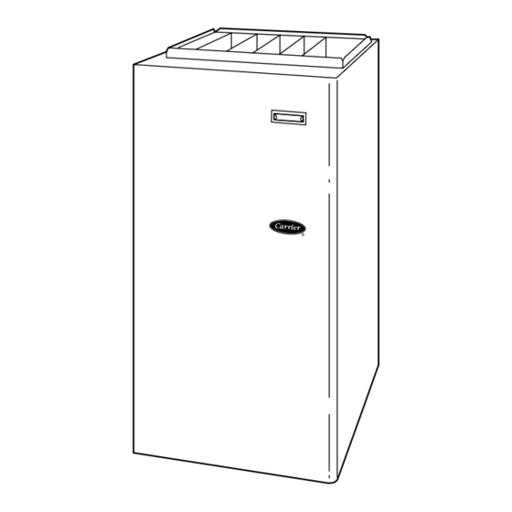
4-way multipoise fixed-capacity condensing gas furnace
Hide thumbs
Also See for 58MCB:
Table of Contents
Advertisement
Quick Links
Visit www.carrier.com
Service and Maintenance Instructions
NOTE: Read the entire instruction manual before starting the
installation.
This symbol → indicates a change since the last issue.
ELECTRICAL SHOCK, FIRE, OR EXPLOSION
HAZARD
Failure to follow safety warnings exactly could result in
dangerous operation, serious injury, death, or property dam-
age.
Improper servicing could result in dangerous operation,
serious injury, death, or property damage.
- Before servicing, disconnect all electrical power to furnace.
- When servicing controls, label all wires prior to disconnect-
ing. Reconnect wires correctly.
- Verify proper operation after servicing.
ELECTRICAL SHOCK, FIRE OR EXPLOSION
HAZARD
Failure to follow this warning could result in possible damage
to this equipment, serious personal injury, or death.
The ability to properly perform maintenance on this equip-
ment requires certain expertise, mechanical skills, tools, and
equipment. If you do not possess these, do not attempt to
perform any maintenance on this equipment other than those
procedures recommended in the User's Manual.
Manufacturer reserves the right to discontinue, or change at any time, specifications or designs without notice and without incurring obligations.
Book 1 4
PC 101
Tab 6a 8a
For Sizes 040-140, Series 100
A93040
Printed in U.S.A.
Catalog No. 58MCB-1SM
4-Way Multipoise
Condensing Gas Furnace
FIRE OR EXPLOSION HAZARD
Failure to follow this warning could cause corrosion of heat
exchanger, fire, personal injury, or death.
Never store anything on, near, or in contact with the furnace,
such as:
1. Spray or aerosol cans, rags, brooms, dust mops, vacuum
cleaners, or other cleaning tools.
2. Soap powders, bleaches, waxes or other cleaning com-
pounds, plastic or plastic containers, gasoline, kerosene,
cigarette lighter fluid, dry cleaning fluids, or other volatile
fluids.
3. Paint thinners and other painting compounds, paper bags,
or other paper products.
SAFETY CONSIDERATIONS .....................................................1
GENERAL......................................................................................2
CARE AND MAINTENANCE.....................................................3
Cleaning and/or Replacing Air Filter.......................................3
Blower Motor and Wheel Maintenance...................................3
Cleaning Burners ......................................................................5
Cleaning Heat Exchangers........................................................6
Primary Heat Exchangers ......................................................6
Secondary Heat Exchangers ..................................................8
Flushing Collector Box and Drainage System ........................8
Servicing Hot Surface Igniter...................................................9
Electrical Controls and Wiring.................................................9
Checking Heat Tape Operation (If Applicable) ....................10
Winterizing..............................................................................10
WIRING DIAGRAM...................................................................11
TROUBLESHOOTING ...............................................................11
Status Codes............................................................................11
Component Tests ....................................................................12
SAFETY CONSIDERATIONS
Recognize safety information. This is the safety-alert symbol
When you see this symbol on the furnace and in instructions or
manuals, be alert to the potential for personal injury.
Understand the signal words DANGER, WARNING, CAUTION,
and NOTE. These words are used with the safety-alert symbol.
DANGER identifies the most serious hazards which will result in
severe personal injury or death. WARNING signifies hazards
which could result in personal injury or death. CAUTION is used
to identify unsafe practices which may result in minor personal
injury or product and property damage. NOTE is used to highlight
suggestions which will result in enhanced installation, reliability,
or operation.
Pg 1
58MCB
Fixed-Capacity
8-05
Replaces: 58MCA-10SM
.
Advertisement
Table of Contents

Related Manuals for Carrier 58MCB


Summary of Contents for Carrier 58MCB
-
Page 1: Table Of Contents
Manufacturer reserves the right to discontinue, or change at any time, specifications or designs without notice and without incurring obligations. Book 1 4 PC 101 Printed in U.S.A. Catalog No. 58MCB-1SM Pg 1 8-05 Replaces: 58MCA-10SM Tab 6a 8a... -
Page 2: General
ELECTRICAL SHOCK AND UNIT DAMAGE HAZARD Failure to follow this caution may result in minor personal injury or damage to furnace. Label all wires prior to disconnection when servicing con- trols. Wiring errors can cause improper and dangerous operation. GENERAL →... -
Page 3: Care And Maintenance
WASHABLE FILTER FILTER RETAINER WASHABLE FILTER FILTER FILTER RETAINER SUPPORT A93045 Fig. 4—Filter Installed for Side Inlet A93046 Fig. 3—Bottom Filter Arrangement NOT move or shuffle your feet, DO NOT touch ungrounded objects, etc.). CUT HAZARD 4. If you touch ungrounded objects (recharge your body with Failure to follow this caution may result in personal injury. - Page 4 → 6. Remove screws securing blower assembly to blower shelf and slide blower assembly out of furnace. Detach ground wire and disconnect blower motor harness plugs from blower motor. → NOTE: Blower wheel is fragile. Use care. PLUG 7. Clean blower wheel and motor by using a vacuum with soft brush attachment.
-
Page 5: Cleaning Burners
13. Reconnect wires. CELL PANEL Refer to furnace wiring diagram, and connect thermostat leads if previously disconnected. (See Fig. 21.) MANIFOLD MOUNTING NOTE: Refer to Table 1 for motor speed lead reconnection if SCREW leads were not identified before disconnection. UNIT DAMAGE HAZARD Failure to adjust the heating speed may shorten heat ex- changer life. -
Page 6: Cleaning Heat Exchangers
A93087 Fig. 9—Combustion-Air Intake Housing Gasket Repair 22. Replace main furnace door. Step 4—Cleaning Heat Exchangers The following items should be performed by a qualified service technician. IGNIT ER WIRES MUST PRIMARY HEAT EXCHANGERS BE PLACED IN THIS SLOT A05074 If the heat exchangers get an accumulation of light dirt or dust on the inside, they may be cleaned by the following procedure: →... -
Page 7: Furnace Pressure And Drain Tubing Diagram
TUBE ROUTING Furnace is shipped from factory in upflow configuration. Pressure tube and drain tube routing MUST match the diagrams below. Tube location when used in UPFLOW application Condensate Trap on LEFT Condensate Trap; Factory Installed Side Optional in Blower Shelf BURNER ENCLOSURE (Blower access panel removed) BURNER ENCLOSURE... -
Page 8: Secondary Heat Exchangers
burners. Burner flames should be clear blue, almost transpar- ent. (See Fig. 11.) → UNIT DAMAGE HAZARD Failure to follow this caution may result in furnace compo- nent damage. → Do not use wire brush or other sharp object to inspect or FIRE OR EXPLOSION HAZARD dislodge materials in secondary heat exchangers as cutting the Failure to follow the safety warnings exactly could result in... -
Page 9: Servicing Hot Surface Igniter
IGNITER EXTENDED IGNITER BRACKET HANDLE BRACKET 9/16˝ IGNITER BRACKET 11/16˝ MOUNTING SCREW A05075 2-5/32˝ → Fig. 13—Igniter Bracket A04181 → Fig. 14—Igniter 16. Replace main furnace door. 6. To replace igniter and bracket assembly, reverse items 5a Step 6—Servicing Hot Surface Igniter through 5d. -
Page 10: Checking Heat Tape Operation (If Applicable)
FIELD 24-V WIRING FIELD 115-, 208/230-, 460-V WIRING FACTORY 24-V WIRING FACTORY 115-V WIRING NOTE 2 THERMOSTAT FIVE WIRE FIELD-SUPPLIED TERMINALS DISCONNECT THREE-WIRE HEATING-ONLY 208/230- OR BLOWER DOOR SWITCH 460-V THREE PHASE 208/230-V SINGLE PHASE AUXILIARY 115-V FIELD- J-BOX SUPPLIED NOTE 1 DISCONNECT CONDENSING... -
Page 11: Wiring Diagram
TWINNING AND/OR COMPONENT TEST BLOWER OFF-DELAY TERMINAL J2 JUMPER BLOWER OFF-DELAY HUMIDIFIER TERMINAL (24-VAC 0.5 AMP MAX.) 24-V THERMOSTAT TERMINALS TRANSFORMER 24-VAC CONNECTIONS TEST/TWIN 0.5 AMP@24VAC 3-AMP FUSE FUSE 3-AMP SEC-2 SEC-1 LED OPERATION & EAC-2 DIAGNOSTIC LIGHT PL1-LOW VOLTAGE MAIN HARNESS CONNECTOR 115-VAC(L2)NEUTRAL CONNECTIONS... -
Page 12: Component Tests
respond with blower operation.) This places the control in the status recall mode and displays the first code stored in memory. Record the code. After the last code is displayed the control will perform the component test, and then return to normal standby mode. -
Page 13: Component Test
SERVICE If status code recall is needed, briefly remove then reconnect one main limit wire to display stored status code. On RED LED boards do not remove power or blower door before initiat- ing status code recall. After one status code recall is completed component test will occur. LED CODE STATUS CONTINUOUS OFF - Check for 115VAC at L1 &... - Page 14 PRINTED CIRCIUT BOARD TRAN NEUTRAL NOTE PRINTED CIRCIUT BOARD...
-
Page 20: Book.
[ ] Packaged Service Training [ ] Classroom Service Training A94328 Copyright 2005 CARRIER Corp. • 7310 W. Morris St. • Indianapolis, IN 46231 Manufacturer reserves the right to discontinue, or change at any time, specifications or designs without notice and without incurring obligations.