
Related Manuals for Great Dane Super Surfer Series II GSKH2352S


Summary of Contents for Great Dane Super Surfer Series II GSKH2352S
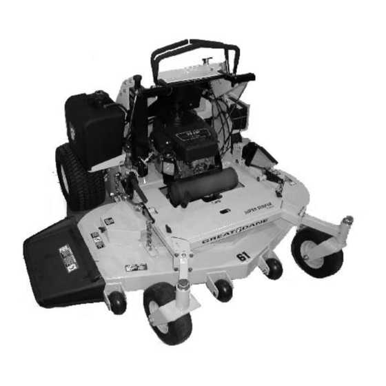
- Page 1 ® Super Surfer Series II GSKH1848S, GSKH2352S, GSKH2561S GSKW1948S, GSKW2352S, GSKA1948S OPERATOR’S MANUAL 200036 REV. 04/11/2007 North American Version...
- Page 3 WARNING: The Engine Exhaust from this product contains chemicals known to the State of California to cause cancer, birth defects or other reproductive harm. California Proposition 65 Warning All information, illustrations and specifications in this manual are based on the latest information at the time of publication.
-
Page 4: Safety Labels
ENGINE MODEL, SPECIFICATION, AND SERIAL NUMBER: Model Number _________________________________________ Specification _________________________________________ Serial Number _________________________________________ Safety Labels Understanding The Machine Safety Labels The machine safety labels shown in this section are placed in important areas on your machine to draw attention to potential safety hazards. On your machine safety labels, the words DANGER, WARNING, and CAUTION are used with this safety-alert symbol. - Page 5 NOTE: Tampering with emission controls and components by unauthorized personnel may result in severe fines or penalties. Emission controls and components can only be adjusted by EPA and/or CARB authorized service centers. Contact your Great Dane Equipment Retailer concerning emission controls and component questions.
-
Page 6: Using A Spark Arrestor
• Only operate in good light, keeping away from holes and hidden hazards. • Be sure all drives are in neutral and parking brake is engaged before starting engine. Only start engine from the operator’s position. Use seat belts if provided. •... - Page 7 • Do not mow in reverse. • Shut off blades when you are not mowing. • • Park machine safely before leaving the operator station for any reason including emptying the catchers or unplugging the chute. Protect Children • Death or serious injury can occur when young children associate having fun with a lawn mowing machine simply because someone has given them a ride on a machine.
- Page 8 • Wear close fitting clothing and safety equipment appropriate for the job. • While mowing, always wear substantial footwear and long trousers. Do not operate the equipment when barefoot or wearing open sandals. • Wear a suitable protective device such as earplugs. Loud noise can cause impairment or loss of hearing.
-
Page 9: Operator Station Controls
• Prevent fire and explosion caused by static electric discharge. Static electric discharge can ignite fuel vapors in an ungrounded fuel container. • Never fill containers inside a vehicle or on a truck or trailer bed with a plastic liner. Always place containers on the ground away from your vehicle before fueling. - Page 10 K-Choke L-Throttle Lever M-Park Brake Lever Mower Deck Controls A-Mower Deck Lift Levers B-Height-of-Cut (HOC) Pin Miscellaneous Controls A-Free-Wheeling Valves OPERATING Mounting and Dismounting Machine Safely 1. Step on operator’s platform (A) at the rear of machine to mount the machine.
-
Page 11: Leveling Mower Deck
3. Stop engine and lock park brake. 4. Remove retaining ring (A) from HOC pin (B). 5. Push down on deck lift lever (C). 6. Remove HOC pin. 7. Place HOC pin in desired height hole (D). 8. Release deck lift lever (C). 9. - Page 12 a. Loosen jam nuts (D) and adjust nuts (E) on each U-bolt until side-to side level is reached. b. Tighten jam nuts (D). Checking Level (Front-to-Rear) 1. Set height-of-cut (HOC) to the 76 mm (3 in.) cutting height position. NOTE: The height of the rear blade tip should be between 3-6 mm (1/ 8-1/4 in.) higher than the front blade tip.
- Page 13 Adjusting Overall Cutting Height NOTE: When adjusting U-bolts, maintain a minimum clearance of 3 mm (1/8 in.) between mower deck and stop pads. Adjust both sides of the mower deck equally. All lift chains must remain taut. 1. Adjust four U-bolts (A) (two on each side of deck) until blade tip height is within 73-79 mm (2-7/8-3-1/8 in.) of the 76 mm (3 in.) setting.
- Page 14 Testing Operator Presence Switch NOTE: Ensure OPC switch bracket is depressed when standing on operator’s station. 1. Stand on operator’s platform with motion control levers in the NEUTRAL position. 2. Start engine. 3. Unlock park brake. 4. Step completely off operator’s platform. Result: The engine must stop.
-
Page 15: Using The Throttle
Using the Throttle • Push throttle lever (A) forward to the fast position (B) when mowing. • Move throttle lever (A) to the half fast position (C) when starting and warming the engine. • Pull throttle lever (A) backward to the slow position (D) to idle engine. Do not run engine at slow idle any longer than necessary for cooldown after mowing. - Page 16 Forward: • Push both motion control levers forward at the same time. Reverse: • Pull both motion control levers past center rearward at the same time. Gentle Left Turn: • Push right motion control lever further forward than the left motion control lever.
-
Page 17: Starting Engine
Starting Engine CAUTION: Avoid injury! Engine exhaust fumes contain carbon monoxide and can cause serious illness or death. Move the machine to an outside area before running the engine. Do not run an engine in an enclosed area without adequate ventilation. - Page 18 Using Pump Free-Wheel Valves CAUTION: Avoid injury! With the free-wheeling valve open, the machine will have unrestricted motion. • The machine may free-wheel out of control if the free- wheeling valve is opened with the machine on an incline. • Park the machine on a level surface before opening the free-wheeling valve.
-
Page 19: Service Intervals
Service Intervals Servicing Your Machine IMPORTANT: Avoid Damage! Operating in extreme conditions may require more frequent service intervals: • Engine components may become dirty or plugged when operating in extreme heat, dust or other severe conditions. • Engine oil may lose efficiency if vehicle is operated constantly at slow or low engine speeds or with frequent short trips. -
Page 20: Service Engine
Lubricating Deck Lift Pivot Points • Lubricate two front deck lift pivot grease fittings (A) and two rear deck lift pivot grease fittings (B). Lubricating Pump Idler Pivot • Lubricate one pump idler pivot grease fitting (A). Lubricating Mower Deck Spindles •... -
Page 21: Checking Engine Oil Level
Checking Engine Oil Level IMPORTANT: Avoid Damage! Failure to check the oil level regularly could lead to serious engine problems if oil level is low: Check oil level before operating. Keep oil level between the FULL and the ADD marks. Check oil level when engine is stopped, level, and is cooled so oil has had time to drain into the sump. -
Page 22: Replacing Fuel Filter
14. Insert dipstick. Tighten cap. 15. Start engine and run at slow throttle for approximately two minutes. Check for leaks around filter and drain valve. 16. Stop engine. 17. Check oil level: • Remove dipstick cap. Wipe dipstick clean. NOTE: Allow dipstick cap to rest on threads of filler tube when checking oil level. -
Page 23: Checking Hydraulic Oil Level
3. Slide hose clamps (A) away from fuel filter (B). 4. Place drain pan under hoses to catch any fuel that may be left in the hoses. 5. Disconnect hoses from fuel filter (B). 6. Install new fuel filter (B). •... - Page 24 IMPORTANT: Avoid Damage! Do not add oil beyond FULL mark. Oil capacity after draining may be less than dry fill capacity. Check oil level before filling completely. NOTE: Dry fill capacity for hydraulic system is 3.1L (3.3 qt). 10. Fill oil reservoir with approximately 1.9L (2 qt) of oil. 11.
- Page 25 3. Remove four cap screws (A). 4. Remove rear shield (B). CAUTION: Avoid injury! Tensioning spring is under high tension. Wear gloves and safety glasses, and use a spring puller to install and remove spring. Picture Note: Traction drive belt idler pulley bottom view. 5.
- Page 26 Adjusting Motion Control Return to Neutral (RTN) Linkages: CAUTION: Avoid injury! Fingers or loose clothing can get caught in rotating parts. Stop engine and wait for all moving parts to stop before servicing. 1. Stop engine. 2. Lock park brake. 3.
-
Page 27: Service Steering & Brakes
Picture Note: Arrow shows direction of speed control bar (A) movement when decreasing forward speed. 2. Loosen lock lever (B) on speed control bar (A). • To decrease forward speed, pull speed control bar (A) toward the operator’s station. • To increase forward speed, push speed control bar (A) forward (away from operator’s station). -
Page 28: Service Mower
Service Mower Removing and Installing Mower Deck Shield CAUTION: Avoid injury! Help prevent serious personal injury. Do not operate the mower without the mower deck shield installed. Removing Mower Deck Shield: 1. Park machine safely. (See Parking Safely in the SAFETY section.) 2. - Page 29 5. Release mower deck drive belt tension by turning adjuster nut (A) counterclockwise until two threads remain protruding through adjuster nut (A). 6. Disconnect idler spring (B) from idler arm (C) using a spring puller tool. 7. Loosen idler pulley retaining nut (D) just enough to allow idler pulley (E) to tilt, allowing belt (F) to clear fixed belt guide (G).
- Page 30 Disconnect battery or remove spark plug wire before making repairs. IMPORTANT: Avoid Damage! When replacing mower blades, always use genuine Great Dane Service Parts. NOTE: Only replace blades. Never straighten or weld them. Checking Mower Blades 1. Park machine safely. (See Parking Safely in the Safety Section).
-
Page 31: Service Electrical
• Keep original bevel (A) when grinding. • Blade should have 0.40 mm (1/64 in.) cutting edge (B) or less. • Balance blades before installing. Balancing Blades CAUTION: Avoid injury! Mower blades are sharp. Always wear gloves when handling mower blades or working near blades. 1. - Page 32 CAUTION: Avoid injury! Battery electrolyte contains sulfuric acid. It is poisonous and can cause serious burns: • Wear eye protection and gloves. • Keep skin protected. • If electrolyte is swallowed, get medical attention immediately. • If electrolyte is splashed into eyes, flush immediately with water for 15-30 minutes and get medical attention.
-
Page 33: Service Miscellaneous
A - Booster Battery B - Disabled Vehicle Battery 1. Connect positive (+) booster cable to booster battery (A) positive (+) post (C). 2. Connect the other end of positive (+) booster cable to the disabled vehicle battery (B) positive (+) post (D). 3. - Page 34 Important: Avoid damage! Dirt and water in fuel can cause engine damage: • Clean dirt and debris from the fuel tank opening. • Use clean, fresh, stabilized fuel. • Fill the fuel tank at the end of each day’s operation to keep condensation out of the fuel tank.
- Page 35 Checking Tire Pressure CAUTION: Avoid injury! Explosive separation of tire and rim parts is possible when they are serviced incorrectly: Do not attempt to mount a tire without the proper equipment and experience to perform the job. Do not inflate the tires above the recommended pressure. Do not weld or heat a wheel and tire assembly.
-
Page 36: Troubleshooting
2. Dry thoroughly to avoid water spots. Cleaning and Repairing Metal Surfaces Cleaning: Follow automotive practices to care for your vehicle painted metal surfaces. Use a high-quality automotive wax regularly to maintain the factory look of your vehicle’s painted surfaces. Repairing Minor Scratches (surface scratch): 1. - Page 37 Check Engine Lacks Power • Reduce load. • Plugged air intake system. • Plugged fuel filter. • Improper type of fuel. Drain tank and fill with correct fuel. • Clean cooling fins to help prevent overheating. • Replace spark plugs. Engine Uses Too Much Oil •...
- Page 38 Mower Deck Check Discharge Chute Plugged • Grass is wet-mow grass only when dry. • Raise cutting height. • Mow with engine at full fast throttle. • Ground speed too fast for conditions. • Correct installation of deck drive belt. Mower Deck Vibrates •...
- Page 39 1. Change engine oil and filter while engine is warm. 2. Service air filter if necessary. 3. Clean debris from engine air intake screen. 4. On gas engines: • Remove spark plugs. Put 30 mL (1 oz) of clean engine oil in cylinders. •...
-
Page 40: Specifications
Connect Battery CAUTION: Avoid injury! Prevent Battery Explosions: • Keep sparks, lighted matches, and open flame away from the top of battery. Battery gas can explode. • Never check battery charge by placing a metal object across the posts. Use a volt-meter or hydrometer. •... - Page 41 Part numbers may change, use part numbers listed below when you order. If a number changes, your dealer will have the latest number. When you order parts, your Great Dane dealer needs your machine serial number and engine serial number. These are the numbers that you recorded in the Product Identification section of this manual.
- Page 42 SERVICE MISCELLANEOUS Wiring Schematics Service Miscellaneous Service Miscellaneous - 40...
- Page 43 SERVICE MISCELLANEOUS Service Miscellaneous Kawasaki Wiring Schematics Service Miscellaneous - 41...
- Page 44 Service Miscellaneous Left Hydrostatic Pump Assembly Pump Block Charge Pump System Charge Check Shock Valve (Reverse) Manual Bypass Left Wheel Motor Cooling Orifice System Charge Check Shock Valve (Forward) SERVICE MISCELLANEOUS Hydraulic Schematics Charge Relief Valve Right Hydrostatic Pump Assembly Right Wheel Motor Inlet Filter Hydraulic Reservoir...
- Page 45 SERVICE MISCELLANEOUS Service Miscellaneous - 43...
- Page 46 MAIN FRAME, TRACTION DECK, CONSOLE AND OPC PLATFORM Main Frame, Traction Deck, Console and OPC Platform - 44...
- Page 47 MAIN FRAME, TRACTION DECK, CONSOLE AND OPC PLATFORM Ref. No. Part No. TCA14936 Frame - TCA14946 Frame - D15356 Fender, Left D15355 Fender, Right 200038 Weight 19M7270 Cap Screw 19M7803 Cap Screw 14M7396 JD7842 Lubrication Fitting 200218 Deck Shield Assembly TCA15350 Deck Shield Assembly M119352...
- Page 48 DRIVE CONTROLS AND LINKAGE Drive Controls and Linkage - 46...
- Page 49 DRIVE CONTROLS AND LINKAGE Ref. No. Part No. D18069 200080 200081 D13029 14M7303 J16913 D13028 D38157 D18093 19M7547 14M7400 D13308 D13309 34H60 TCA15195 19M7862 14M7397 19M7785 191256 19H1905 200116 14H650 19M7372 14M7360 D14081 TCU19201 TCU19202 TCU18929 TCU18931 TCU18932 TCU18930 TCU19203 TCU19204 TCU19209 TCU19205...
-
Page 50: Park Brake
PARK BRAKE Park Brake - 48 MX20211... - Page 51 Ref. No. Part No. D18038 Switch 19M7373 Cap Screw 14M7360 K40003 Lock Nut 19H1801 Cap Screw TCU12713 Spacer GDU10037 Bushing AM105809 Swivel TCU20956 D12352 Lever 14H846 J16931 Spring Pin 34H268 Roll Pin TCA15174 TCA15070 Shaft 24H1413 Bushing D18079 Grip 24H1341 Washer 19M3804 Cap Screw...
- Page 52 HYDROSTATIC PUMP DRIVE AND PTO Hydrostatic Pump Drive and PTO - 50...
- Page 53 HYDROSTATIC PUMP DRIVE AND PTO Ref. No. Part No. GDU10025 V-Belt TCA15316 Pulley, RH Pump D28091 Pulley, Engine Drive GDA10017 PTO Clutch GDA10006 Bracket D18314 Idler GDA10004 Idler Post D18403 Bushing GDA10005 Idler Arm D18071 Spring, Idler D14213 Cap Screw E63526 Flange Nut 403490...
- Page 54 HYDROSTATIC COMPONENTS 20 23 MX20223 Hydrostatic Components - 52...
- Page 55 HYDROSTATIC COMPONENTS Ref. No. Part No. TCA15122 TCA15373 Hydraulic Reservoir D18379 Hose Clamp TCA15078 Wheel Motor D14196 Elbow Fitting, Pump End TCA14966 Pump, LH TCA14965 Pump, RH 14M7518 03M7192 Carriage Bolt, Pump Mounting GDA10137 Oil Filter GDA10066 Elbow Fitting 313270 Elbow Fitting 14M7517 Lock Nut, Reservoir Mounting...
-
Page 56: Hydraulic Schematic
HYDRAULIC SCHEMATIC A - Left Hydrostatic Pump Assembly B - Pump Block C - Charge Pump D - System Charge Check Shock Valve (Reverse) E - Manual Bypass F - Left Wheel Motor G - Cooling Orifice H - System Charge Check Shock Valve (Forward) I - Charge Relief Valve J - Right Hydrostatic Pump Assembly MX20151... -
Page 57: Platform Components
PLATFORM COMPONENTS Ref. No. Part No. D18038 Park Brake Switch D38128 Com. Spring 1.22x.162x2.5 200299 Platform Weldment 200618 Platform Plate 200619 Platform Tab LH Plate 200655 Miner GBR-6 Bumper 200691 Platform Wedge 200693 Platform Tab Plate 200767 OPC Anchor 200770 Spring Washer 200935 OPC Cover... -
Page 58: Fuel Tank And Lines
FUEL TANK AND LINES MX20229 Fuel Tank and Lines - 56... - Page 59 Ref. No. Part No. TCA15021 Fuel Tank 181251 Cap, Fuel D18144 Grommet TCA15048 Fuel Pickup M68342 Clamp M88753 Hose, Fuel, 1/4 in. SAE 30-R7 14M7400 AM116304 Filter 03M7191 Cap Screw 19M7865 Cap Screw TCU18489 Bracket FUEL TANK AND LINES Description NOTES Fuel Tank and Lines - 57 Qty.
- Page 60 KOHLER ENGINE AND RELATED COMPONENTS KOHLER Engine and Related Components - 58...
- Page 61 KOHLER ENGINE AND RELATED COMPONENTS Ref. No. Part No. D28121 TCA15389 X6PMTX-S 03M7188 19M8317 14M7396 14M7298 D18427 D18359 D24020 M63431 14H846 12M7032 * NOTE: See authorized KOHLER servicing engine dealer for engines and engine related service items. Always reference the engine model number when ordering parts. Description Muffler Gasket...
- Page 62 KAWASAKI ENGINE AND RELATED COMPONENTS...
- Page 63 KAWASAKI ENGINE AND RELATED COMPONENTS Ref. No. Part No. TCA15321 Muffler 191601 Gasket Kit, TCA16240 Oil Drain Fitting TCU19288 Shield, Muffler 03M7188 Carriage Bolt, Engine Mounting 19M8317 Cap Screw, Engine Mounting 14M7396 Flange Lock Nut, Engine Mounting 12M7065 Lock Washer D18427 Cable, Choke TCA15051...
- Page 64 KOHLER LOGIC SCHEMATIC MX20146 NOTES KOHLER Logic Schematic - 62...
- Page 65 KAWASAKI LOGIC SCHEMATIC Kawasaki Logic Schematic - 63...
- Page 66 BATTERY, ELECTRICAL HARNESS AND COMPONENTS Battery, Electrical Harness and Components - 64...
- Page 67 BATTERY, ELECTRICAL HARNESS AND COMPONENTS Ref. No. Part No. TCA15061 Wiring Harness 200204 Wiring Harness 19M7372 Cap Screw 14M7360 AM123716 Relay 57M7120 Fuse 24H1283 Washer AM129887 Hour Meter TCU13098 Clip TCA15075 Key Switch M110159 TCU17401 Ignition Key AM118802 Switch, PTO M72685 Spacer D28159...
- Page 68 CASTER WHEELS AND REAR WHEELS Caster Wheels and Rear Wheels - 66 MX20207...
- Page 69 CASTER WHEELS AND REAR WHEELS Ref. No. Part No. TCU17863 Spacer, Caster Bushing E14625 Seal D38035 Bearing Assembly, Caster Wheel D28051 Bearing Assembly, Caster Yoke 11M7083 Cotter Pin A12188 Castle Nut M135582 Cap, Bearing JD7844 Grease Fitting D25004 Yoke D33007 Spacer, Caster Wheel D28097 Cap Screw...
- Page 70 MOWER DECK LIFT LINKAGE MX20232 Mower Deck Lift Linkage - 68...
- Page 71 MOWER DECK LIFT LINKAGE Ref. No. Part No. D18225 Grip E63526 GDA10010 Lift Arm, LH Rear GDA10009 Lift Arm, RH Rear P46402 Snap Ring 24H1413 Washer R27434 Snap Ring N10215 150749 Chain, Deck Lift 19M8162 Cap Screw GDU10048 U-Bolt 14H1058 TCU15817 Rod, Deck Lift 200075...
-
Page 72: Mower Deck
MOWER DECK MX20240 Mower Deck - 70... - Page 73 Ref. No. Part No. TCA15385 Mower Deck, 48" S/O TCA15386 Mower Deck, 52" S/O TCA15387 Mower Deck, 61" S/O TCU14540 Bushing TCU18344 Support Strap TCU18847 Belt, Engine-to-Blades, 48" Deck TCU18848 Belt, Engine-to-Blades, 52" Deck TCU18849 Belt, Engine-to-Blades, 61" Deck TCU18744 Roller, Anti-Scalp TCU18744 Roller, Anti-Scalp...
-
Page 74: Mower Deck Spindles
MOWER DECK SPINDLES Mower Deck Spindles - 72... - Page 75 Ref. No. Part No. 200262 Spindle Assembly 200046 Ball Bearing 200042 Housing 200044 Spacer 200196 Shaft, Spindle 200045 Bolt 967333 Nut, Pulley D18209 Pulley, Cutter Housing, 48" Deck D18084 Pulley, Cutter Housing, 52" Deck D18211 Pulley, Cutter Housing, 61" Deck D13024 Spacer, Pulley 967348...
-
Page 76: Labels And Decals
LABELS AND DECALS Labels and Decals - 74... - Page 77 TCU16481 Decal TCU18852 Decal LABELS AND DECALS Description Qty. NOTES Labels and Decals - 75 Remarks "Great Dane" Danger-Rotating Blades No Step (61" only) Warning-Avoid Tipover Patent Super Surfer Series II Warning-Hot Surface Park Brake General Caution Danger-Rotating Belts Danger-Blade Contact...