
Related Manuals for Rinnai Energysaver RHFE-1004T


Summary of Contents for Rinnai Energysaver RHFE-1004T
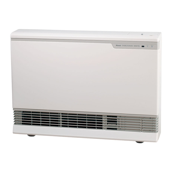
- Page 1 Installation and User Manual RHFE-1004T RHFE-1004T Energysaver Space Heater Important. Read these instructions carefully before attempting installation or use of this appliance. All work must be carried out by competent persons.
- Page 2 Rinnai Corporation - Japan Manufactured under a Quality System Certified as complying with ISO 9001 by an Accredited Certification Body. ISO 9001 APPROVED BY JIA...
-
Page 3: Table Of Contents
CONTENTS Features of your 1004T Getting to know your New 1004T Control Panel Layout Important Points Customers Operating Information How to operate the Heater Adjusting Temperature Economy Mode Function Lock Other Operating Information Installation Location Installation Instructions Making Electrical Connection Wiring Diagram for Programmer Summary of Position for Terminal Installation Instructions... -
Page 4: Features Of Your 1004T
FEATURES OF YOUR 1004T Push Button Ignition: Only one touch of the ON/OFF button is required to operate the heater. 7 Step Automatic Heat Control with electronic thermostat. The fan is also controlled by the thermostat. Economy Mode: An energy saving feature that reduces the room temperature by 3˚C over a 90 minute period. -
Page 5: Getting To Know Your New 1004T
GETTING TO KNOW YOUR NEW 1004T CONTROL PANEL OPERATION/TEMP- ERATURE CONTROL DISPLAY FILTER INDICATOR OPERATION INDICATOR WARM AIR OUTLET HUMIDIFIER OPEN THE DOOR AND POUR WATER INTO THE TRAY. GAS CONNECTION AIR FILTER 1/2" BSP (15mm) FLUE TERMINAL THERMISTOR EXHAUST PIPE POWER CORD RATING PLATE PLUG 230VAC... -
Page 6: Control Panel Layout
CONTROL PANEL ALL BUTTONS BEEP WHEN OPERATED. TEMPERATURE ON/OFF BUTTON DISPLAY Easy operation SHOWS EITHER THE One touch ignition TEMPERATURE OR CODED ERROR MESSAGES. CONTROL PANEL ENERGY SAVING FUNCTION TEMPERATURE BUTTON LOCK BUTTONS Lamp is “green” Lamp is “green” “ ”... -
Page 7: Important Points
IMPORTANT POINTS Do not use for any other purpose except These clearances should be maintained at all heating. times. 250mm 50mm 50mm 1000mm Do not allow cur tains or other flammable Keep flammable materials, trees shrubs etc. materials to come into contact with the heater. away from flue terminal. - Page 8 IMPORTANT POINTS Don’t allow children to ‘post’ articles in the Don’t place any articles containing liquids on louvres. top of the heater. Don’t spray aerosols on the heater whilst it is in Do not place articles on or against the heater. operation.
-
Page 9: How To Operate The Heater
HOW TO OPERATE THE HEATER I Turning ON GPress the ON/OFF button The ON indicator will illuminate green. The combustion fan will rotate. Ignition will take 5 10 seconds and the ON/Combustion indicator will change from green to red to let you know that the burner has ignited. -
Page 10: Adjusting Temperature
ADJUSTING THE TEMPERATURE Displaying, setting and adjusting the room temperature can only be done when the heater is operating. When the unit is first operated, the room temperature is set at 22˚C. Set the desired room temperature with the up and down buttons while looking at the display section. -
Page 11: Function Lock
FUNCTION LOCK The Function Lock will help to prevent accidental operation as well as small children from altering the heater settings. The Function Lock can be operated either when the heater is running, or in the “stand by” mode, by pressing the up and down buttons simultaneously. -
Page 12: Other Operating Information
The heater and its flue must be installed correctly by an authorised person, and the installation must conform to all local regulations. The installation also must comply with the instructions supplied by Rinnai. This heater must be serviced, installed and removed by an authorised person. -
Page 13: Location
LOCATION When positioning the unit the main points This unit is not designed to be built in. governing the location are: (1) Flueing (2) Warm Air Distribution. This heater must not be installed where curtains or other combustible materials could come into contact with it. - Page 14 Do not flue into natural draught flues or fireplaces, Standard Installation of flue manifold. this unit can only be used with a Rinnai flue kit. Diagram below shows minimum clearances and (A flue kit is available to flue right through to the distances from obstructions.
- Page 15 LOCATION Do not install the unit in an unusually dusty area. WEATHERBOARD WALLS DRILL THROUGH CENTRE OF WEATHERBOARD FROM OUTSIDE, THEN DRILL FROM INSIDE THROUGH PLASTERBOARD. (mm) Use flue guard if the terminal is easily accessible to children. Check local regulations. Flue guards are available as an optional extra.
-
Page 16: Installation Instructions
INSTALLATION INSTRUCTIONS Important Safety Instructions 1. Gas Safety (Installation & Use) Regulations 1998 are the ‘Rules in Force’. In your own interest and that of safety, it is law that all gas appliances shall be installed by competent persons in accordance with the above regulations. Failure to install appliances correctly could lead to prosecution. -
Page 17: Making Electrical Connection
MAKING ELECTRICAL CONNECTION WARNING: This appliance must be earthed. This appliance is suitable for use on 230V 50Hz mains only and external wiring must be carried out to I.E.E. Regulations. Connect the appliance to the mains electrical supply. A 3amp switched fuse spur with contact separation of at least 3mm on all poles, must be provided as a means of electrically isolating the heater for servicing purposes. -
Page 18: Wiring Diagram For Programmer
WIRING DIAGRAM FOR PROGRAMMER For multiple Rinnai appliances using a single time clock. – 16 –... -
Page 19: Summary Of Position For Terminal
POSITIONING THE FLUE TERMINAL Dimension Terminal Position Distance Directly below an opening, air brick, opening windows, etc. 300mm Above an opening, air brick, opening window, etc. 300mm Horizontally to an opening, air brick, opening window, etc. 300mm Below gutters, soil pipes or drain pipes. 75mm Below eaves. -
Page 20: Installation Instructions
INSTALLATION INSTRUCTIONS I The following components are supplied with your 1004T Flue Manifold Spare rubber seal (For weatherboard installations) Wall Brackets Insulation Back Spacer Clip Plastic tie for air inlet (M4) Floor For Back Spacer Set Brackets (M5) For Wall Brackets Air inlet hose (M4 20) For Flue Lock Stopper... -
Page 21: Using The Template
USING THE TEMPLATE 1. Fold the template along the bottom so that the bottom of the feet are at the edge of the paper. 2. Tape the template to the wall in the position that the heater is to be installed, with the feet sitting on the floor. -
Page 22: Sleeve And Manifold Installation
SLEEVE AND MANIFOLD INSTALLATION METHOD FOR STANDARD WALLS 1. Dis-assemble Manifold from Sleeve. The flue consists of 3 parts, sleeve, inside connectors and tube, outside terminal; (dis- assemble by pulling hard on outside terminal and inner connections, then pull sleeve off outer terminal). - Page 23 SLEEVE AND MANIFOLD INSTALLATION METHOD FOR STANDARD WALLS 5. Check rubber seal is in place on terminal. Terminal seal 6. Installation of Terminal "TOP" mark "A" Label From outside, insert terminal into sleeve with the “A” mark at the top. Left hand side fixing tie is marked “LEFT”...
-
Page 24: Fitting Unit
FITTING UNIT Fix Flue Adapter to Flue. Air Inlet Hose Manifold with Locking Clamp S as shown below. Connect Air Inlet Hose to Manifold Inlet. Do not kink the hose. Secure with plastic tie as-shown below. Locking clamp S Flue Manifold Plastic tie Flue Adapter Inlet elbow... - Page 25 FITTING UNIT 3. Fit the screw clamp between the sliding tube 4. Slide the insulation sleeve up to the flue and the flue elbow. Secure with the 4mm screw manifold. Slip the securing clip over the sleeve supplied. The flue outlet is now locked into as shown.
-
Page 26: Forced Flue Heater Extension Kits
FORCED FLUE HEATER EXTENSION KITS EXTENSION SET PARTS AND INSTALLATION GUIDE FOT - 102 FOT - 103 FOT - 114 FOT - 115 • This extension set is to be used for installations requiring extra distance. MAXIMUM FLUE LENGTH 7 METRES. REDUCE LENGTH 1 METRE FOR EACH BEND USED. (E.G. -
Page 27: How To Install
Flue pipe. Caution: Check to see there is no debris in pipe or hose. I HOW TO INSTALL MODEL: RHFE-1004T Example: Using 2 sets of extension set and 1 bent set. Example: Using 2 metre extension set. - Page 28 1. How to connect exhaust pipes Exhaust pipe Exhaust pipe Fit inside Male end Male end Female end Female end Pipe stopper B Pipe stopper B Pipe stopper A To connect the exhaust pipes, fit the male end into the female end and clamp with pipe stopper A to prevent slipping.
- Page 29 I CAUTIONS 1. Maximum extendable length 2. To prevent water condensation FOR BEST ROOM AIR HUMIDITY, KEEP WATER IN THE HUMIDIFIER TRAY. Condensed water may accumulate here, and cause a blockage preventing combustion. • 7 metres. Reduce length 1 metre for each bend used.
- Page 30 4. Wherever the air intake hose and exhaust pipe run sideways, try to have the exhaust pipe on top (to prevent the air intake hose from sagging Exhaust pipe onto the exhaust pipe). Exhaust pipe Air intake hose Air intake hose –...
-
Page 31: Testing
TESTING Purge air and swarf from gas line. Connect gas. Replace top spacer, clipping the spacer into the Gas connection should be made with a union fitting wall brackets at the same time as attaching it to the and a suitable isolation valve for servicing. Do not heater. -
Page 32: Gas Pressure Setting Procedure
GAS PRESSURE SETTING PROCEDURE 1. Disconnect/Isolate 230V power supply. 2. Carefully remove front cover and disconnect the plug attached to the PCB on front cover. 3. Connect manometer to pressure test point on the front of the gas valve. 4. Reconnect 230V power. 5. -
Page 33: Gas Conversion Procedure
GAS CONVERSION PROCEDURE 1. Disconnect/isolate 230V power supply 2. Carefully remove front cover and disconnect the plug attached to the PCB on the front cover. 3. Press PCB switch while unit is off to change to gas type setting mode. Current gas type code will be indicated (L1: LPG;... -
Page 34: Care Of Your 1004T
Room too large Check with retailer Gas turned off at meter Turn gas on Function Lock Set Cancel Function Lock If you are unsure about the way the unit is operating, contact Rinnai UK Ltd. or your supplier. – 32 –... -
Page 35: Pre-Service Check
PRE-SERVICE CHECK Before asking for a service call please check the following. These points are part of the normal operation of the unit. At ignition : The fan is started automatically after a short delay. Warm air does not start when the burner This is to allow the heat exchanger to warm up, lights. -
Page 36: Error Messages
In all cases, you may be able to clear the Error Message simply by turning the heater OFF, then ON again. If the Error Message still remains or returns on the next operation contact Rinnai UK Ltd or your Supplier and arrange for a service call. -
Page 37: Safety Devices
SAFETY DEVICES Overheat Switch: This device automatically cuts the gas off if the heater exceeds a predetermined temperature. This is normally caused by an obstruction in front of the louvres, or a blocked fan filter. If this switch operates, turn the unit off, remove the obstruction (clean filters) and let the unit cool off before re- operating. -
Page 38: Dimensions
DIMENSIONS Air Filter 357.5 Filter Indicator Operation Indicator GAS CONNECTION Clip R338 Cavity Opening R265 – 36 –... -
Page 39: Wiring Diagram
WIRING DIAGRAM – 37 –... -
Page 40: Warranty
WARRANTY As the purchaser of this high quality model RHFE-1004T product you are provided with the following warranty: Free Parts Heat Exchanger 15 Years* 1 Year All other parts 1 Year * Full Heat Exchanger replacement (parts only) for all 15 years. -
Page 41: Specifications
Ignition: Electronic-Continuous Spark. Electrical Supply: 230V, 50Hz Fan: Centrifugal 7 Speed Fan. Rinnai are continually updating and improving products, therefore specifications are subject to change without prior notice. SERVICE CONTACT POINT Contact: Rinnai UK Ltd. 9 Christleton Court Manor Park... - Page 42 NOTES – 40 –...
- Page 43 NOTES – 41 –...
- Page 44 January 2006 1004F-2280...