Generac Power Systems GP Series Owner's Manual
50 hz
Hide thumbs
Also See for GP Series:
- Diagnostic and repair manual (98 pages) ,
- Owner's manual (92 pages) ,
- Owner's manual (66 pages)
Table of Contents
Advertisement
Available languages
Available languages
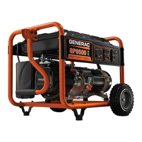
Owner's Manual
50 Hz, GP Series Portable Generator
www.generac.com or 1-888-436-3722
DEADLY EXHAUST FUMES! ONLY use OUTSIDE
far away from windows, doors and vents!
NOT INTENDED FOR USE IN CRITICAL LIFE
SUPPORT APPLICATIONS.
SAVE this Manual. Provide this manual to any
operator of the generator.
Advertisement
Table of Contents

Related Manuals for Generac Power Systems GP Series


Summary of Contents for Generac Power Systems GP Series
- Page 1 Owner's Manual 50 Hz, GP Series Portable Generator DEADLY EXHAUST FUMES! ONLY use OUTSIDE far away from windows, doors and vents! NOT INTENDED FOR USE IN CRITICAL LIFE SUPPORT APPLICATIONS. SAVE this Manual. Provide this manual to any ...
-
Page 2: Table Of Contents
Table of Contents Introduction ............. 1 Maintenance ............13 Performing Scheduled Maintenance ......13 Read this Manual Thoroughly ......... 1 Maintenance Schedule ..........13 Safety Rules ............1 3.2.1 GP5000/GP6000 Maintenance Schedule ..13 3.2.2 GP2600 Maintenance Schedule .......13 Registration ............3 Product Specifications ..........14 3.3.1 GP5000/GP6000 Generator Specifications ..14 3.3.2... -
Page 3: Introduction
Introduction INTRODUCTION Thank you for purchasing this model by Generac Power Systems, Indicates a hazardous situation or action which, Inc. This model is a compact, high performance, air-cooled, if not avoided, could result in minor or moderate engine driven generator designed to supply electrical power to injury. -
Page 4: Electrical Hazards
Safety Rules ELECTRICAL HAZARDS • Never use the generator or any of its parts as a step. Stepping on the unit can stress and break parts, and may result in • The generator produces dangerously high voltage when in dangerous operating conditions from leaking exhaust gases, operation. -
Page 5: Registration
Safety Rules REGISTRATION Register your product online at www.generac.com to receive important product information or updates. MODEL NO: SERIAL NO: Unit ID Location... -
Page 6: General Information
The generator requires some assembly prior to using it. If problems arise when assembling the generator, please call an authorized dealer at www.generac.com/Dealer Locator. 1.2.1 ASSEMBLING THE ACCESSORY KIT Refer to the instructions below and Figures 1A through 1E to install the handle, feet, and wheels. - Page 7 General Information Figure 1B – Handle Assembly/Foot Assembly (GP2600) Figure 1D – Wheel Assembly (GP5000/GP6000) BEND ONE TAB OUTWARD AFTER AXLE PIN (G) IS INSERTED THROUGH THE FRAME Figure 1E – Wheel Assembly (GP2600) Figure 1C – Foot Assembly (GP5000/GP6000)
-
Page 8: Battery Cable Connection (Electric Start Only)
Operation 1.2.2 BATTERY CABLE CONNECTION (ELECTRIC START 13. Fuel Gauge – Shows fuel level in tank. 14. Oil Fill – Add oil here. ONLY) 15. Recoil Starter – Use to start engine manually. The unit has been deliberately shipped with the battery cables 16. - Page 9 Operation Figure 2C - Control Panel (GP2600) Figure 3B - Generator Controls (GP2600) Figure 3A - Generator Controls (GP5000/GP6000) Figure 3C - Generator Controls (GP5000/GP6000)
-
Page 10: Hourmeter (Gp5000/Gp6000 Only)
Operation 2.2 HOURMETER (GP5000/GP6000 ONLY) Figure 3D - Generator Controls (GP2600) The Hourmeter tracks hours of operation for scheduled maintenance (Figure 4): There will be a "CHG OIL" message every 100 hours. The message will flash one hour before and one hour after each 100 hour interval, providing a two hour window to perform service. -
Page 11: Receptacle
Figure 5 - 230 Volt AC, 16 Amp, CEE 7/4, Type F Receptacle To obtain contact information for the nearest authorized dealer, go to www.generac.com/Dealer Locator. Never operate in an enclosed area or indoors! NEVER use in the home, in a vehicle, or in... -
Page 12: System Ground
Operation 2.4.1 SYSTEM GROUND Proper grounding of the generator will help prevent electrical shock in the event of a ground fault condition in the generator or in The generator has a system ground that connects the generator connected electrical devices. Proper grounding also helps dissipate frame components to the ground terminals on the AC output static electricity, which often builds up in ungrounded devices. -
Page 13: Adding Gasoline
Operation 2.7 STARTING PULL START ENGINES Any attempt to crank or start the engine before it has been properly serviced with the Never start or stop engine with electrical recommended oil may result in an engine devices plugged into the receptacles AND failure. -
Page 14: Starting Electric Start Engines
Maintenance Figure 11 - Engine ON/OFF Switch 5. To start engine, press and hold the Start/Run/Stop switch (control panel) in the “Start” position. The engine will crank and attempt to start. When the engine starts, release the ENGINE ON/OFF SWITCH switch to the run position. -
Page 15: Charging The Battery (Electric Start Units Only)
Maintenance 2.11 CHARGING THE BATTERY (ELECTRIC START 3.1 PERFORMING SCHEDULED MAINTENANCE UNITS ONLY) It is important to perform service as specified in the Maintenance Schedule for proper generator operation, and to ensure that the generator complies with the applicable emission standards for the duration of its useful life. -
Page 16: Product Specifications
Notes Maintenance 3.3 PRODUCT SPECIFICATIONS 3.4 GENERAL RECOMMENDATIONS The warranty of the generator does not cover items that have been 3.3.1 GP5000/GP6000 GENERATOR SPECIFICATIONS subjected to operator abuse or negligence. To receive full value from the warranty, the operator must maintain the generator as Rated Power ..............5.0/6.0 kW** instructed in this manual. -
Page 17: Checking Oil Level
Maintenance 3.4.4 CHECKING OIL LEVEL 3.4.7 BATTERY REPLACEMENT (IF APPLICABLE) See the “Before Starting the Generator” section for information on NOTE: checking the oil level. The oil level should be checked before each The battery shipped with the generator has been fully charged. use, or at least every eight hours of operation. -
Page 18: Service Air Cleaner
Maintenance Figure 16 - Spark Arrestor 3.5.2 GP2600 AIR CLEANER The engine will not run properly and may be damaged if using a dirty air filter. Clean the air filter every 25 hours (Figure 18). Clean or replace more often if operating under dusty conditions. 1. -
Page 19: General
Maintenance 3.7 GENERAL 5. Remove spark plug and pour about 1/2 ounce (15 ml) of engine oil into the cylinder. Cover spark plug hole with rag. The generator should be started at least once every 30 days and Pull the recoil starter a couple times to lubricate the piston be allowed to run at least 30 minutes. -
Page 20: Troubleshooting
Troubleshooting 4.1 TROUBLESHOOTING GUIDE PROBLEM CAUSE CORRECTION Engine is running, but no AC output 1. Circuit breaker is open. 1. Reset circuit breaker. is available. 2. Poor connection or defective cord set. 2. Check and repair. 3. Connected device is bad. 3. -
Page 21: Notes
Notes... -
Page 22: Warranty
FOR GP SERIES PORTABLE GENERATORS For a period of two (2) years from the date of original sale, Generac Power Systems, Inc. (Generac) warrants its GP Series generators will be free from defects in materials and workmanship for the items and period set forth below. Generac will, at its discretion, repair or replace any part that, upon examination, inspection and testing by Generac or a Generac Authorized Warranty Service Dealer, is found to be defective. - Page 23 ОПН А С ОНОСН ! О О НА О О О АППА А Н АСС АН НА СПО О АН СОС А А Н С С Н О СП Н Н АС А...
- Page 24 С...
- Page 25 Т Р О О НА А ОПАСН С А С О О Н С ОП С А О АН С О А РЕДУ РЕ ДЕ ИЕ О...
- Page 26 П...
- Page 27 П...
- Page 28 О – – – – – – – – – – – – – – – –...
- Page 29 О ВСТАВЬТЕ ОСЕВУЮ ЧЕКУ (G) В РАМУ И ОТОГНИТЕ ОДНУ НОЖКУ НАРУЖУ...
- Page 32 0000.0 ЗНАЧОК С КНОПКА СБРОСА ПЕСОЧНЫМИ (ПРИ НАЛИЧИИ) ЧАСАМИ...
- Page 33 Н О А ! Н О А А С Н О О Н П...
- Page 34 SAE 30 SA E 30 10W -30 10W-30 Синтетическое 5W-30 Синтетиче ское 5 W-30 ВЫВОД ДЛЯ ЗАЗЕМЛЕНИЯ Предполагаемый диапазон рабочих температур Т Р ...
- Page 35 РЕДУ РЕ ДЕ ИЕ Н НН Н О С А Н О С А Н ООПАСН Н О ENCENDIDO MARCHE APAGADO ARRÊT ВЫКЛЮЧЕНИЕ ПОДАЧИ ТОПЛИВА Топливный бак НЕ ПЕРЕЛИВАТЬ за выступ Топливо...
- Page 36 Двигатель Вкл./ Выкл. Переключатель (Только для двигателей GP5000) РЫЧАГ ПОДСОСА ВЛЕВО = ПОДСОС (ЗАПУСК) ВПРАВО = РАБОТА РЕДУ РЕ ДЕ ИЕ Н НН...
- Page 37 П П Р З ЕМ ДЛЯ З РЯД Г У ТР Й ТВ...
- Page 38 Т Р П...
- Page 39 Т Р Т Р О А Н С С...
- Page 40 Зажим Экран Глушитель ЗАЖИМ...
- Page 41 Т Р П Н О С А П Н Н О С А ...
- Page 44 О АН ННА Н А АН НА ПО А Н Н А О С А АН Н П АН П АН П А А НАС О А А АН Н АСП ОС АН С НА...