White Rodgers 1F89-211 Installation And Operation Instructions Manual
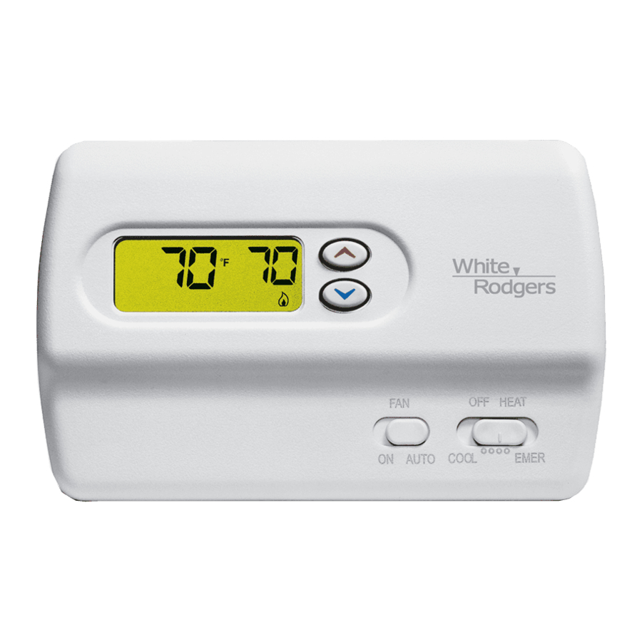
Non-programmable electronic digital heat pump thermostat
Hide thumbs
Also See for 1F89-211:
- Installation and operation instructions manual (9 pages) ,
- Brochure & specs (2 pages) ,
- Installation and operation instructions manual (6 pages)
Table of Contents
Advertisement
Operator: Save these instructions for future use!
FAILURE TO READ AND FOLLOW ALL INSTRUCTIONS CAREFULLY
BEFORE INSTALLING OR OPERATING THIS CONTROL COULD CAUSE
PERSONAL INJURY AND/OR PROPERTY DAMAGE.
Your new White-Rodgers Digital Thermostat uses the
technology of a solid-state microcomputer to provide precise
temperature control.
Features:
• Simultaneous heat and cool setpoint storage
• Setpoint storage in case of power loss
• Pre-set temperature control
• LCD continuously displays setpoint and room temperature
This thermostat is intended for use with a low voltage system;
do not use this thermostat with a line voltage system. If in doubt
about whether your wiring is millivolt, line, or low voltage, have
it inspected by a qualified heating and air conditioning contrac-
tor or electrician.
Do not exceed the specification ratings.
All wiring must conform to local and national electrical codes
and ordinances.
This control is a precision instrument, and should be handled
carefully. Rough handling or distorting components could cause
the control to malfunction.
CAUTION
!
To prevent electrical shock and/or equipment damage,
disconnect electric power to system at main fuse or
circuit breaker box until installation is complete.
ELECTRICAL DATA
Electrical Rating:
20 to 30 VAC 50/60 Hz. or D.C.
0.05 to 1.0 Amps (Load per terminal)
1.5 Amps Maximum Total Load (All terminals combined)
THERMAL DATA
Setpoint Temperature Range:
45°F to 90°F (7°C to 32°C)
Operating Ambient Temperature Range:
32°F to 105°F
Operating Humidity Range:
0 to 90% RH (non-condensing)
Shipping Temperature Range:
-4°F to 149°F
• Continuous Backlit display option
• °F/°C convertibility
• Temperature range 45° to 90°F
• R, C, Y, W2, G, O/B, E, and L terminals for single or two-
transformer systems
• Optional "AA" batteries to provide continuous temperature
display during loss of AC power
Do not use on circuits exceeding specified voltage.
Higher voltage will damage control and could cause
shock or fire hazard.
Do not short out terminals on gas valve or primary
control to test. Short or incorrect wiring will damage
thermostat and could cause personal injury and/or
property damage.
Thermostat installation and all components of the
system shall conform to Class II (current limited)
circuits per the NEC code. Failure to do so could cause
a fire hazard.
APPLICATIONS
For use with:
• Standard heat pump systems with electric, gas or oil Aux
heat with 24 VAC HOT and COMMON available
• Single-stage heat pump systems with no Aux heat with
24 VAC HOT and COMMON available
DO NOT USE WITH:
• Millivolt systems
• Systems exceeding 30 VAC and 1.5 amps
• 3-wire zoned hydronic heating systems
www.white-rodgers.com
www.emersonclimate.com
1F89-211
Non-programmable Electronic Digital
Heat Pump Thermostat
INSTALLATION AND
OPERATION INSTRUCTIONS
DESCRIPTION
PRECAUTIONS
WARNING
!
SPECIFICATIONS
PART NO. 37-6233F
Replaces 37-6233E
1338
Advertisement
Table of Contents

Related Manuals for White Rodgers 1F89-211


Summary of Contents for White Rodgers 1F89-211
-
Page 1: Specifications
1F89-211 Non-programmable Electronic Digital Heat Pump Thermostat INSTALLATION AND OPERATION INSTRUCTIONS Operator: Save these instructions for future use! FAILURE TO READ AND FOLLOW ALL INSTRUCTIONS CAREFULLY BEFORE INSTALLING OR OPERATING THIS CONTROL COULD CAUSE PERSONAL INJURY AND/OR PROPERTY DAMAGE. DESCRIPTION Your new White-Rodgers Digital Thermostat uses the •... -
Page 2: Remove Old Thermostat
INSTALLATION REMOVE OLD THERMOSTAT Screw anchors 1. Shut off electricity at the main fuse box until installation is complete. Ensure that electrical power is disconnected. 2. Remove the front cover of the old thermostat. With wires still attached, remove wall plate from the wall. If the old thermostat has a wall mounting plate, remove the thermostat and the wall mounting plate as an assembly. -
Page 3: Wiring Diagram For Single Transformer Systems
WIRING THERMOSTAT SYSTEM See Note ** SYSTEM Changeover MONITOR Emergency Relay* SWITCH Compressor Relay Relay Relay Contactor (Stage 2) 24 VAC 120 VAC Neutral * Changeover Relay is energized in COOL when O/B switch is in the “O” position Changeover Relay is energized in HEAT when O/B switch is in the “B” position TRANSFORMER ** Jumper required to use a single Aux Heat for both Second Stage Heat and Emergency (Class II current limiting) -
Page 4: Check Thermostat Operation
CHECK THERMOSTAT OPERATION If at any time during testing your system does not operate 1. Move SYSTEM switch to EMER position. EMER will flash properly, contact a qualified service person. on the display. Turn on power to the system. 2. Press to adjust the thermostat above room temperature. -
Page 5: Installer/Configuration Menu
INSTALLER/CONFIGURATION MENU CONFIGURATION MENU The configuration menu chart summarizes the configuration options. An explanation of each option follows. The configuration menu allows you to set certain thermostat Press to change to the next menu item. To exit operating characteristics to your system or personal require- the menu, move the SYSTEM switch to HEAT or COOL. -
Page 6: Troubleshooting
OPERATION OPERATING FEATURES SETTING THE THERMOSTAT Now that you are familiar with the thermostat buttons and display, This thermostat is very easy to operate. Set the SYSTEM read the following information to learn about the many features switch to either HEAT or COOL then press until of the thermostat. - Page 7 NOTES...
- Page 8 HOMEOWNER HELP LINE: 1-800-284-2925 White-Rodgers is a business of Emerson Electric Co. The Emerson logo is a www.white-rodgers.com trademark and service mark of Emerson Electric Co. www.emersonclimate.com...