
Related Manuals for MSI G41M-P25


Summary of Contents for MSI G41M-P25
- Page 1 G 4 1 M - P 2 5 / G 4 1 M - S 0 2 m D T H E R B D R R D MODEL NO. MS-7592 U S E R G U I D E...
- Page 2 TOP QUALITY & STABILITY • Most Stable Components with Top Quality OTP Sensor Area Tantalum Core Aluminum Core DrMOS II Hl-C CAP Solid CAP 1 (Next-Gen OMOS) (8X Longer Uhdme) (ЭО* Higher Power) (10. Yean IMHone uf. • All Military Class III components have passed the following MIL-STD-810G tests - Low Pressure Test - High Temperature Test - Low Temperature Test...
- Page 3 MS-7592 FCC-B RADIO FREQUENCY INTERFERENCE STATEMENT This equipment has been tested and found to comply with the limits for a class В digital device, pursuant to part 15 of the FCC rules. These limits are designed part 15 of the FCC rules. These limits are designed to provide reasonable pro- О...
- Page 4 TRADEMARKS All trademarks are the properties of their respective owners. • MSI® is registered trademark of Micro-Star Int'l Co.,Ltd. • NVIDIA® is registered trademark of NVIDIA Corporation. • ATI® is registered trademark of ATI Technologies, Inc.
- Page 5 MS-7592 SAFETY INSTRUCTIONS • Always read the safety instructions carefully. • Keep this User Manual for future reference. • Keep this equipment away from humidity. • Lay this equipment on a reliable flat surface before setting it up. • The openings on the enclosure are for air convection hence protects the equipment from overheating.
-
Page 6: English
MSI will comply with the product take back requirements at the end of life of MSI-branded products that are sold into the EU. You can return these products to local collection points. - Page 7 MSI zal overeenkomstig de richtlijn handelen voor de pro- ducten die de merknaam MSI dragen en verkocht zijn in de EU. Deze goederen kunnen geretourneerd worden op lokale inzamelingspunten.
- Page 8 MSI si adeguera a tale Direttiva ritirando tutti i prodotti marchiati MSI che sono stati venduti all'interno dell'Unione Europea alia fine del loro ciclo di vita.
- Page 9 MS-7592 TABLE OF CONTENT ENGLISH GETTING STARTED SPECIFICATIONS Ю REAR PANEL HARDWARE SETUP BIOS SETUP t R < H A|5f 8 f 7 | Afgf BIOS tf S FRANQAIS POUR COMMENCER SPECIFICATIONS PANNEAU ARRltRE INSTALLATION DU MATERIEL REGLAGE BIOS DEUTSCH EINLEITUNG SPEZIFIKATIONEN HINTERES ANSCHLUSSPANEL...
- Page 10 Ж в Ф Л ЯШ W® « Я & Й BIOS Й Й В Ф И ttlTfelC I / O A * Л. Д - P O i T i z v Ь Т - У У B i o s r o i s s...
-
Page 11: Getting Started
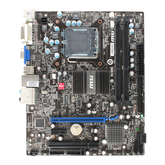
GETTING STARTED Thank you for choosing the G41M-P25/ G41M-S02 (MS-7592 v6.x) Micro-ATX mainboard. The G41M-P25/ G41M-S02 is based on Intel* G41 & ICH7flCH7R chipset for optimal system efficiency. Designed to fit the advanced Intel* Core™2 Quad/ Core™2 Duo/ Pentium*/ Celeron* processor in LGA775 package, the G41M-P25/ G41M-S02 delivers a high performance and professional desktop platform solution. -
Page 12: Specifications
Memory • 2 DDR3 1333(OC)/1066/ 800 DIMM slots (8GB Max) (For more information on compatible components, please visit http://www. msi. com/index.php ?func=testreport) • Supports LAN 10/100/1000 Fast Ethernet by Realtek® 8111DL Audio • Chip integrated by Realtek® ALC888S VC2/ ALC889 •... - Page 13 Form Factor • Micro-ATX (200mm x 244mm) Mounting • 6 mounting holes If you need to purchase accessories and request the part numbers, you could search the product web page and find details on our web address below http-.Uwww. msi. com/index.php...
-
Page 14: Hardware Setup
REAR PANEL The rear panel provides the following connectors: Keyboard DVI-D Port VGA Port USB Ports SS-Out HARDWARE SETUP This section provides instructions on CPU and memory installation, as well as jumper settings on the mainboard. While doing the installation, be careful in hold- ing the components and follow the installation procedures. - Page 15 MS-7592 Follow the steps below to install the CPU & cooler correctly. Wrong installation will cause the damage of your CPU & mainboard. The CPU socket has a plastic cap on it to protect the contact from damage. Before you install the CPU, always cover it to protect the socket pins.
-
Page 16: Installing Memory Modules
Installing Memory Modules The memory module has only one notch on the center and will only fit in the right orientation. Insert the memory module vertically into the DIMM slot. Then push it in until the golden finger on the memory module is deeply inserted in the DIMM slot. The plastic clip at each side of the DIMM slot will automatically close when the memory module is properly seated. -
Page 17: Connectors
MS-7592 ATX 24-Pln Power Connector JPWR1 This connector allows you to connect an ATX 24-pin power supply. To connect the ATX 24-pin power supply, make sure the plug of the power supply is inserted in the proper orientation and the pins are aligned. Then push down the power supply firmly into the connector. - Page 18 IDE Connector. IDE1 (optional) This connector supports IDE hard disk drives, optical disk drives and other IDE devices. IMPORTANT If you install two IDE devices on the same cable, you must configure the drives to cable select mode or separately to master / slave mode by setting jumpers. Refer to IDE device documentation supplied by the vendors for jumper setting instructions.
-
Page 19: Cd-Ln/S/Pdif-Out Connector
MS-7592 S/PDIF-Out Connector SPDOUT1 This connector is used to connect S/PDIF (Sony & Philips Digital Interconnect Format) interface for digital audio transmission. CD-ln Connector JCD1 (optional) This connector is provided for external audio input. Front Panel Connectors: JFP1, JFP2 These connectors are for electrical connection to the front panel switches and LEDs. - Page 20 Front Panel Audio Connector JAUD1 This connector allows you to connect the front panel audio and is compliant with Intel® Front Panel I/O Connectivity Design Guide. Front USB Connector JUSB1, JUSB2 This connector, compliant with Intel® I/O Connectivity Design Guide, is ideal for connecting high-speed USB interface peripherals such as USB HDD, digital cam- TPM Module connector JTPM1 This connector connects to a TPM (Trusted Platform Module) module.
- Page 21 MS-7592 Chassis Intrusion Connector JCI1 This connector connects to the chassis intrusion switch cable. If the chassis is opened, the chassis intrusion mechanism will be activated. The system will record this status and show a warning message on the screen. To clear the warning, you must enter the BIOS utility and clear the record.
- Page 22 Overckx* FSB Switch: OC_SW1 (optional) You can overclock the FSB to increase the processor frequency by changing the switch. Follow the instructions below to set the FSB. B U B B B B B B B В У У 1 2 3 1 2 3 1 2 3 1 2 3...
- Page 23 MS-7592 PCI Express Slot The PCI Express slot supports the PCI Express interface expansion card. PCI Express x16 slot. PCI Express x1 slot. PCI Slot The PCI slot supports LAN card, SCSI card, USB card, and other add-on cards that comply with PCI specifications. IMPORTANT When adding or removing expansion cards, make sure that you unplug the power supply first.
-
Page 24: Bios Setup
BIOS SETUP Power on the computer and the system will start POST (Power On Self Test) process. When the message below appears on the screen, press <DEL> key to enter Setup. Press DEL to enter SETUP If the message disappears before you respond and you still wish to enter Setup, restart the system by turning it OFF and On or pressing the RESET button. -
Page 25: Specifications
MS-7592 BIOS Setting Password Use this menu to set BIOS setting Password. Cell Menu Use this menu to specify your settings for frequency/voltage control. M-Flash Use this menu to read/ flash the BIOS from USB media device. Load Fail-Safe Defaults Use this menu to load the BIOS default values that are factory settings for system operations. - Page 26 CPU Technology Support Press <Enter> to enter the submenu, that shows the technologies that the in- stalled CPU supported. Intel EIST The Enhanced Intel SpeedStep technology allows you to set the performance level of the microprocessor whether the computer is running on battery or AC power.
- Page 27 MS-7592 fail to retain data. This item applies only when synchronous DRAM is installed in the system. tRAS When the DRAM Timing Mode sets to [Manual], the field is adjustable. This set- ting determines the time RAS takes to read from and write to a memory cell. tRTP When the DRAM Timing Mode sets to [Manual], the field is adjustable.
- Page 28 you are plagued by EMI, set to Enabled for EMI reduction. Remember to disable Spread Spectrum if you are overclocking because even a slight jitter can introduce a temporary boost in clock speed which may just cause your overclocked proces- sor to lock up.
- Page 29 M-FLASH SETUP M-Flash funcion allows you to flash BIOS from USB drive/ storage drive (FAT/ FAT32 format only), or allows the system to boot from the BIOS file inside USB drive (FAT/ FAT32 format only). To use M-Flash, first boot/reboot the computer and the system will start POST (Power On Self Test) process.
- Page 30 IMPORTANT * Please refer to the block diagram below about the M-Flash function. Select BIOS file from the root directory of USB/ Storage drive (FAT/FAT32 format only) in "Load BIOS source file from" field Please check USB drive/ Storage drive/ BIOS file status and reboot the system manually again.