Table of Contents
Advertisement
Copyright and Warranty Notice
The information in this document is subject to change without notice and does not
represent a commitment on part of the vendor, who assumes no liability or
responsibility for any errors that may appear in this manual.
No warranty or representation, either expressed or implied, is made with respect to
the quality, accuracy or fitness for any particular part of this document. In no event
shall the manufacturer be liable for direct, indirect, special, incidental or
consequential damages arising from any defect or error in this manual or product.
Product names appearing in this manual are for identification purpose only and
trademarks and product names or brand names appearing in this document are
property of their respective owners.
This document contains materials protected under International Copyright Laws. All
rights reserved. No part of this manual may be reproduced, transmitted or
transcribed without the expressed written permission of the manufacturer and
authors of this manual.
If you do not properly set the motherboard settings causing the motherboard to
malfunction or fail, we cannot guarantee any responsibility.
Advertisement
Table of Contents

Related Manuals for Abit BE6


Summary of Contents for Abit BE6
- Page 1 Copyright and Warranty Notice The information in this document is subject to change without notice and does not represent a commitment on part of the vendor, who assumes no liability or responsibility for any errors that may appear in this manual. No warranty or representation, either expressed or implied, is made with respect to the quality, accuracy or fitness for any particular part of this document.
-
Page 3: Table Of Contents
BE6 Motherboard User’s Manual Table of Contents CHAPTER 1. INTRODUCTION OF BE6 FEATURES 1-1.Features of This Motherboard 1-2. Specifications 1-3. Layout Diagram 1-4. The System Block Diagram CHAPTER 2. INSTALLING THE MOTHERBOARD 2-1. Installing the Motherboard to the Chassis 2-2. Installation of the Pentium II/III, Celeron CPU 2-3. -
Page 5: Chapter 1. Introduction Of Be6 Features
The BE6 has the HPT366 Ultra ATA/66 Chipset built-in. This means, the BE6 will support Ultra ATA/66 IDE devices. Ultra ATA/66 is the new standard for IDE devices. It enhances existing Ultra ATA/33 technology by increasing both performance and data integrity. -
Page 6: Specifications
Chapter1 Please Note If the operating system or application software cannot handle Year 2000 dates, you will still be facing the Y2K threat because it is not a hardware problem that relates to the motherboard itself. According to Award BIOS, it is BIOS source code released after 31 May 1995 complies with all known Y2K issues;... - Page 7 Introduction of BE6 Features 5. Multi I/O Functions ! 2x Channels of Bus Master IDE Ports supporting up to four Ultra DMA 33/66 devices ! 2x Channels of Bus Master IDE Ports supporting up to four Ultra DMA 33 devices ! PS/2 Keyboard and PS/2 Mouse Connectors ! 1x Floppy Port ( up to 2.88MB)
- Page 8 Chapter1 " " " " Supports Wake On LAN, Keyboard or Mouse, but your ATX power supply 5V standby power must be able to provide at least a 720mA current capacity. Otherwise, the functions may not work normally. " " " " PCI slots 4 and 5 use the same bus master control signal. "...
-
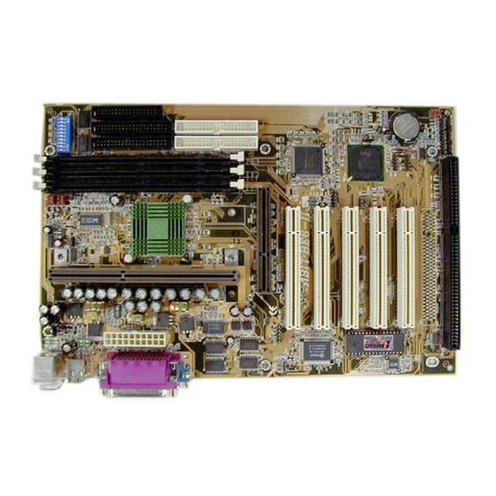
Page 9: Layout Diagram
Introduction of BE6 Features 1-3. Layout Diagram Figure 1-2. Motherboard component location User’s Manual... -
Page 10: The System Block Diagram
Chapter1 1-4. The System Block Diagram Figure 1-3. System diagram of the 440BX chipset... -
Page 11: Chapter 2. Installing The Motherboard
Installing the Motherboard Chapter 2. Installing the Motherboard This BE6 motherboard not only provides all standard equipment for classic personal computers, but also provides great flexibility for meeting future upgrade demands. This chapter will introduce step by step all the standard equipment and will also present, as completely as possible, future upgrade capabilities. -
Page 12: Installing The Motherboard To The Chassis
Chapter2 2-1. Installing the Motherboard to the Chassis Most computer chassis will have a base on which there will be many mounting holes that allows the motherboard to be securely attached and at the same time, prevents short circuits. There are two ways to attach the motherboard to the base of chassis: ! with studs ! or with spacers Please refer to the figure 2-1 that shows the studs and spacers, they may have several types,... -
Page 13: Installation Of The Pentium Ii/Iii, Celeron Cpu
® PPGA processor, you have to use an additional adapter that allows you to use a Celeron PPGA processor in a slot 1 board. For this ABIT makes the SlotKET adapter. Note: ! Installing a heat sink and cooling fan is necessary for proper heat dissipation from your CPU. - Page 14 Chapter2 In order to create a memory array, certain rules must be followed. The following set of rules allows for optimum configurations. ! The memory array is 64 or 72 bits wide. (depending on with or without parity) ! Those modules can be populated in any order. ! Supports single and double density DIMMS.
- Page 15 Installing the Motherboard Step 4. Locate your computer’s 168-pin memory expansion DIMM socket. Step 5. Insert the DIMM module into the expansion socket as shown in the illustration. Note how the module is keyed to the socket. You can refer to figure 2-4 for the details.
-
Page 16: Connectors, Headers And Switches
If your system doesn't have such add-on cards or switches you can ignore some special feature connectors. Figure 2-5. All Connectors and Headers for the BE6 First, Let’s see the headers that BE6 uses, and what their functions are. - Page 17 Installing the Motherboard CON1: ATX Power Input Connector Caution If the power supply connectors are not properly attached to the CON1 power supply, the power supply or add-on cards may be damaged. Attach the connector from the power supply to the CON1 connector here. Remember you have to push the connector from the ATX power supply firmly to the end with the CON1 connector, insuring that you have a...
- Page 18 Chapter2 IR1: IR Header (Infrared) There is a specific orientation for pins 1 through 5, attach the connector from the IR KIT or IR device to the IR1 header (left row only) This motherboard supports standard IR transfer rates. Note: Watch the pin position and the orientation ™...
- Page 19 Installing the Motherboard WOL1: Wake on LAN Header If you have a Network adapter that supports this feature, then you can connect the specific cable from the network adapter to this header. This feature lets you wake up your computer via remote control through a local area network.
- Page 20 2-10 Chapter2 CCMOS1: CMOS Discharge Jumper Jumper CCMOS1 discharge CMOS memory. When you install the motherboard, make sure this jumper is set for normal operation (pin 1 and 2 shorted). See figure 2-6. Normal Operation (Default) Discharge CMOS Figure 2-6. CCMOS1 jumper setting Note Before you clear the CMOS, you have to turn the power off first (including the +5V standby power).
- Page 21 Installing the Motherboard 2-11 PN1 (Pin 1-2-3-4-5): Power LED and Keylock Switch Headers There is a specific orientation for pins 1 through 3. Insert the three-threaded power LED cable to pins 1~3, and the two-threaded keylock cable into pin 4 and pin 5. Check to make sure the correct pins go to the correct connectors on the motherboard.
- Page 22 2-12 Chapter2 PN2 (Pin 1-2): Hardware Reset Switch Header Attach the cable from the case’s front panel Reset switch to this header. Press and hold the reset button for at least one second to reset the system. PN2 (Pin 4-5-6-7): Speaker Header Attach the cable from the system speaker to this header.
- Page 23 PIN 10 Suspend LED active PIN 11 Suspend signal PIN 11 No connection Let’s now see the I/O connectors that BE6 uses, and what their functions are. FDC1 Connector This 34-pin connector is called the “floppy disk drive connector”. You can connect a 360K, 5.25”, 1.2M, 5.25”, 720K, 3.5’’,...
- Page 24 2-14 Chapter2 IDE1 and IDE2 Connectors An IDE hard disk drive ribbon cable has 40 wires and two connectors to provide a connection for two IDE hard disk drives. After connecting the single end to the IDE1 (or IDE2), connect the two connectors on the other end to the IDE hard disk drives (or CD-ROM drive, LS-120, etc.).
- Page 25 Installing the Motherboard 2-15 IDE3 and IDE4: ATA 66/Connectors The BE6 supports the Ultra ATA/66 (Also known as Ultra DMA/66) specification. It enhances existing Ultra ATA/33 technology by increasing both performance and data integrity. This new high-speed interface doubles the Ultra ATA/33 burst data transfer rate to 66.6 Mbytes/sec.
- Page 26 2-16 Chapter2 and host systems. The Ultra ATA/66 protocol and commands are designed to be compatible with existing ATA (IDE) devices and systems. Although a new 40-pin, 80-conductor cable is required for Ultra ATA/66, the chip set pin connector remains the same at 40. Hard drives that support Ultra ATA/66 also support Ultra ATA/33 and legacy ATA (IDE) specifications.
- Page 27 Installing the Motherboard 2-17 Figure 2-11. BE6 back panel connectors Figure 2-11 shows the BE6 back panel connectors, these connectors are for connection to outside devices to the motherboard. We will describe which devices will attach to these connectors below.
- Page 28 2-18 Chapter2 Serial Port COM1 and COM2 Connector This motherboard provides two COM ports, you can connect an external modem, mouse other devices that support this communication protocol. Parallel Port Connector This parallel port is also called an “LPT” port, because it usually connects to the printer.
-
Page 29: Chapter 3. Introduction Of The Bios
Introduction of the BIOS Chapter 3. Introduction of the BIOS The BIOS is a program located on a Flash Memory chip on the motherboard. This program will not be lost when you turn the computer off. This program is also referred to as the boot program. - Page 30 Chapter3 Figure 3-1. CMOS Setup Utility In the BIOS Setup main menu of Figure 3-1, you can see several options. We will explain these options step by step in the following pages of this chapter, but let us first see a short description of the function keys you may use here: ! Press Esc to quit the BIOS Setup.
-
Page 31: Cpu Setup
Introduction of the BIOS ™ 3-1. CPU Setup [SOFT MENU ™ The CPU can be setup through a programmable switch (CPU SOFT MENU II), that replaces the traditional manual hardware configuration. This feature allows the user to more easily complete the installation procedures. You can install the CPU without configuring any jumpers or switches. - Page 32 Chapter3 settings: 233 (66) 266 (66) 300 (66) 300 (100) 333 (66) 350 (100) 366 (66) 400 (66) 400(100) 433 (66) 450 (100) 466 (66) 500 (66) 500 (100) 550 (100) User Define User defined external clock and multiplier factor: User Defined $$$$ $$$$...
- Page 33 Introduction of the BIOS Note The increase by 2.5% of the CPU speed is not a standard feature of this product. It is only for use by our development department to verify that the CPU is able to work normally when CPU speed, operating temperature and power supply are 2.5% higher or lower than the standard values.
- Page 34 Chapter3 Note ® ® According to Celeron PPGA MMX processor types, some Celeron PPGA MMX processors will have the multiplier factor locked and the signal disabled. In this situation, there is no way to choose a higher multiplier factor. AGPCLK/CPUCLK: The default setting is “...
- Page 35 Introduction of the BIOS When you change your CPU: This motherboard has been designed in such a way that you can turn the system on after having inserted a CPU in the socket without having to configure any jumpers or DIP switches.
-
Page 36: Standard Cmos Setup Menu
Chapter3 3-2. Standard CMOS Setup Menu This contains the basic configuration parameters of the BIOS. These parameters include the settings of date, hour, VGA card, FDD and HDD. Figure 3-3. Standard CMOS Setup Menu Date (mm:dd:yy): You can set the date information in this item, month (mm), date (dd) and year (yy). Time (hh:mm:ss): You can set time information in this item, hour (hh), minute (mm) and second (ss). - Page 37 Introduction of the BIOS Normal mode: Standard normal mode supports hard disks of 528MB or less. This mode directly uses positions indicated by Cylinders (CYLS), Heads, and Sectors to access data. LBA (Logical Block Addressing) mode: The earlier LBA mode can support HDDs capacity of up to 8.4GB, and this mode uses a different method to calculate the position of disk data to be accessed.
- Page 38 3-10 Chapter3 Video: You can select the VGA modes for your video adapter, four options are available: MONO ( EGA/VGA ( CGA 40 ( CGA 80 ( Back to MONO. The default setting is EGA/VGA. Halt On: You can select which type of error will cause the system to halt. Five options are available: All Errors ( No Errors ( All, But Keyboard ( All, But Diskette ( All, But Disk/Key ( Back to All Errors.
-
Page 39: Bios Features Setup Menu
Introduction of the BIOS 3-11 3-3. BIOS Features Setup Menu In each item, you can press <F1> at any time to display all the options for this item. Attention BIOS Features Setup Menu has already been set for maximum operation. If you do not really understand each of the options in this menu, we recommend you use default values. - Page 40 3-12 Chapter3 CPU Level 2 Cache: This item is used to enable or to disable the CPU level 2 cache. When the external cache is enabled, the system works faster. The default is Enable. CPU Level 2 Cache ECC Checking: This item is used to enable or to disable the CPU level 2 cache ECC checking function.
- Page 41 Introduction of the BIOS 3-13 Boot Sequence EXT Means: This option lets you boot your computer from a SCSI drive or ATA/66 drive that is connected to IDE3 or IDE4. It has to co-operate with the “Boot Sequence.” (refer to the above setup item) For example, if you want to boot your computer from a SCSI drive, you have to set the “Boot Sequence”...
- Page 42 3-14 Chapter3 item is disabled, the BIOS will use the default setting. Typematic Rate (Chars/Sec): When you press a key continuously, the keyboard will repeat the keystroke according to the rate you have set. (Unit: characters/second) Typematic Rate Delay (Msec): When you press a key continuously, if you exceed the delay you have set here, the keyboard will automatically repeat the keystroke according to a certain rate.
- Page 43 Introduction of the BIOS 3-15 OS Select For DRAM > 64MB: When the system memory is bigger than 64MB, the communication method between the BIOS and the operating system will differ from one operating system to another. If you use OS/2, select OS2;...
- Page 44 3-16 Chapter3 Computer Knowledge: SHADOW What is the SHADOW? The BIOS of standard video or interface cards is stored in ROM, and it is often very slow. With the Shadow feature, the CPU reads the BIOS on the VGA card and copies it into RAM. When the CPU runs this BIOS, the operation is speeded up.
-
Page 45: Chipset Features Setup Menu
Introduction of the BIOS 3-17 3-4. Chipset Features Setup Menu The Chipset Features Setup Menu is used to modify the contents of the buffers in the chipset on the motherboard. Since the parameters of the buffers are closely related to hardware, if the setup is not correct or is false, the motherboard will become unstable or you will not be able to boot up. - Page 46 3-18 Chapter3 DRAM Data Integrity Mode: Two options are available: Non-ECC or ECC. This option is used to configure the type of DRAM in your system. ECC is Error Checking and Correction, when your memory is ECC memory, choose the ECC option. System BIOS Cacheable: You can select Enable or Disable.
- Page 47 Introduction of the BIOS 3-19 Passive Release: Two options are available: Enabled and Disabled. Set the option to enabled or disabled passive release for the Intel PIIX4 chip (Intel PCI to ISA bridge). This function is used to meet the latency of the ISA bus master, if you have an ISA card compatibility problem, you can try to enable or disable this option for optimal result.
- Page 48 3-20 Chapter3 Thermal, Fans Speed and Voltages Monitor: These items list current states of CPU and system temperature as well as fan speed (CPU fan and chassis fan). It can not be changed by the user. The following items list the voltage states of the system power. Just like Thermal & Fan Monitor, it is unchangeable.
-
Page 49: Power Management Setup Menu
Introduction of the BIOS 3-21 3-5. Power Management Setup Menu The difference between Green PCs and traditional computers is that Green PCs have a power management feature. With this feature, when the computer is powered on but inactive, the power consumption is reduced in order to save energy. When the computer operates normally, it is in Normal mode. - Page 50 3-22 Chapter3 2. Use the arrow keys to go to the item you want to configure. To change the settings, use PgUP, PgDn, + or - key. 3. After you have configured the Power Management feature, press Esc to go back to the Main Menu.
- Page 51 Introduction of the BIOS 3-23 System States and Power States Under ACPI, the operating system directs all system and device power state transitions. The operating system puts devices in and out of low-power states based on user preferences and knowledge of how devices are being used by applications. Devices that are not being used can be turned off.
- Page 52 3-24 Chapter3 Doze = 1 hour Standby = 1 hour Suspend = 1 hour Max Saving When the three saving modes are enabled, the system is set up for maximum power savings. Doze = 1 minute Standby = 1 minute Suspend = 1 minute Disable Disable the power management function.
- Page 53 Introduction of the BIOS 3-25 CPU Fan Off Option: CPU fan can be turned off in suspend mode. Modem Use IRQ: You can specify the IRQ for modem use. Doze Mode: When the setting selected for "Power Management" is "User Define", you can define for this mode any delay from 1 minute to 1 hour.
- Page 54 3-26 Chapter3 HDD Power Down: If the system has not accessed data on the hard disk drive during the specified time period, the engine of the HDD will stop in order to save electricity. You can set 1 to 15 minutes or select Disable according to your use of the HDD.
- Page 55 Introduction of the BIOS 3-27 IRQ [3-7, 9-15], NMI: If any IRQ or NMI (Non-Mask Interrupt) activities occur, this will cause the computer to re-count the time elapsed. VGA Active Monitor: If there is any VGA data transfer or any I/O activities, this will cause the computer to re-count the time elapsed.
-
Page 56: Pnp/Pci Configuration
3-28 Chapter3 3-6. PNP/PCI Configuration In this menu, you can change the INT# and IRQ of the PCI bus and other hardware settings. Figure 3-7. PNP/PCI Configuration Menu PNP OS Installed: Device resource assigned by PnP OS or BIOS. Force Update ESCD: If you want to clear ESCD data next time you boot up, and ask the BIOS to reset the settings for the Plug &... - Page 57 Introduction of the BIOS 3-29 Legacy ISA devices compliant with the original PC AT bus specification, requiring a specific interrupt (such as IRQ4 for serial port 1). PCI/ISA PnP devices compliant with the Plug and Play standard, whether designed for the PCI or ISA bus architecture.
-
Page 58: Load Setup Defaults
3-30 Chapter3 status, if you want to change it. For the relations between the hardware layout of PIRQ (the signals from the PIIX4 chipset), INT# (means PCI slot IRQ signals) and devices, please refer to the table below: PCI slot 1 PCI slot 4 Signals PCI slot 2... -
Page 59: Integrated Peripherals
Introduction of the BIOS 3-31 3-8. Integrated Peripherals In this menu, you can change the onboard I/O device, I/O port address and other hardware settings. Figure 3-8. Integrated Peripherals Menu Onboard IDE-1 Controller: The onboard IDE 1 controller can be set as Enabled or Disabled. Master Drive PIO Mode: Auto: The BIOS can auto-detect the transfer mode of the IDE devices in order to set its data transfer rate. - Page 60 3-32 Chapter3 Ultra DMA is a DMA data transfer protocol that utilizes ATA commands and the ATA bus to allow DMA commands to transfer data at a maximum burst rate of 33 MB/sec. Auto: When you select Auto, the system automatically determines the optimal data transfer rate for each IDE device.
- Page 61 Introduction of the BIOS 3-33 Slave Drive Ultra DMA: Auto: When you select Auto, the system automatically determines the optimal data transfer rate for each IDE device. (Default) Disabled: If you encounter the problem of using Ultra DMA devices, you can try to Disable this item.
- Page 62 3-34 Chapter3 Note The mouse wake up function can only be used with the PS/2 mouse, not with a mouse that uses the COM port and USB connection. Mouse Left (Mouse Right) means, you need to double click the mouse left (right) button, for the computer to power on. You also need to note the compatibility issue with your PS/2 mouse, some PS/2 mice cannot wake up the system, because of compatibility problems.
- Page 63 Introduction of the BIOS 3-35 RxD , TxD Active: Set IR transmission/reception polarity as High or Low. IR Transmission Delay: Set IR transmission delays 4 character-time(40 bit-time) when SIR is changed from RX mode to TX mode. Onboard Parallel Port: Sets the I/O address and IRQ of the onboard parallel port.
-
Page 64: Password Setting
3-36 Chapter3 3-9. Password Setting This option allows you to set a password required to start the system (System) or to access to the BIOS (Setup). After you have set a password through the PASSWORD SETTING option, you can enter the Security Option in the “BIOS Features Setup Menu”... -
Page 65: Ide Hard Disk Detection
Introduction of the BIOS 3-37 3-10. IDE Hard Disk Detection After you have installed the hard disk, in old systems, you had to know the hard disk specifications, such as the number of cylinders, heads and sectors, and to enter the relevant information into the hard disk information section. -
Page 66: Save & Exit Setup
3-38 Chapter3 3-11. Save & Exit Setup Figure 3-9. Save & Exit Setup You can save all your selection to CMOS and exit BIOS to reboot your computer. 3-12. Quit Without Saving Figure 3-10. Exit Without Saving You can exit and without saving all your selection to CMOS, then exit BIOS to reboot your computer. -
Page 67: Appendix Abios Flashing User Instructions
BIOS Flashing User Instructions Appendix A BIOS Flashing User Instructions When your motherboard needs to be upgraded with new features or to fix some compatibility problems of the BIOS, you will need to use this BIOS flash utility. This utility is provided by Award Software, and it’s easy to flash by yourself. - Page 68 Appendix A Figure A-2. Award Flash Memory Writer V7.05 Complete Screen Figure A-3 shows you what commands you can use for the flashing program, you need to go into the pure DOS environment and type awdflash, then you will see Figure A-3. Figure A-3.
- Page 69 “NEWBIOS” indicates the file name for the new BIOS which can be downloaded from our web site at http://www.abit.com.tw (the user can choose a different file name in place of NEWBIOS). “SAVEBIOS” indicates the filename of the old system BIOS (the user can choose a different file name in place of SAVEBIOS).
- Page 70 (3) The NEWBIOS file which can be download from ABIT web site. (4) AUTOEXEC.BAT, which has the following content: A:\AWDFLASH NEWBIOS /PY /SN /CC /CD For example, to update the BE6 BIOS version to FZ (BE6_KY.BIN), you need to type: A:\AWDFLASH BE6_KY.BIN /PY /SN /CC /CD 3.
-
Page 71: Appendix Binstalling The Highpoint Xstore Pro Utility
Install HighPoint XStore Pro Utility Appendix B Installing the HighPoint XStore Pro Utility We provide a useful and powerful utility in our product package, HighPoint XStore Pro. What does XStore do? The XStore Pro is a hard disk enhancement utility which can improve system performance. - Page 72 Appendix B XStore Pro in your system, otherwise it will cause system conflict when you install the second bus master driver! ® 2. This Windows 95/98 driver does not support CD-ROM Changers. If you have an ATAPI CD-ROM Changer installed in your system, please do not install this driver! ®...
- Page 73 Install HighPoint XStore Pro Utility This CD-ROM (Or floppy diskette) has the HighPoint XStore Pro drivers. (Version 1.2) The following procedure describes how to install the HighPoint XStore to your system. If you have a floppy diskette but not the CD-ROM, just insert the diskette and run the Setup.exe file to start installation.
- Page 74 Appendix B Step 3: Press the “Next” key, you will see the license screen. Step 4: Press “Yes” to the continue screen below. When installation Step process is done, you will see the screen below. This screen will show up only when you install both XStore Pro and CD Xpress.
- Page 75 Install HighPoint XStore Pro Utility Step 6: Choose the “Yes, I want to restart my computer now.” button, then system will restart. Or you can choose the “No, I will restart my computer later.”. Note You must restart your computer after you installed the XStore Pro utility. Otherwise, software may works not properly.
- Page 76 Appendix B...
-
Page 77: Appendix Chardware Monitoring Function (Installing The Winbond Hardware Doctor Utility)
Hardware Monitoring Function Appendix C Hardware Monitoring Function (Installing The Winbond Hardware Doctor Utility) Winbond Hardware Doctor is a self-diagnostic system for PCs and must be used with the Winbond chipset: W83781D/W83782D/W83783S IC series products. It will protect PC hardware by monitoring several critical items including power supply voltages, CPU &... - Page 78 Appendix C Step 3. You can specify the program install path by clicking “Change Directory” button. Or if you want to use the default path, click the icon to continue the install process. Now the screen will show you the percentage of installation progress.
- Page 79 Hardware Monitoring Function Once any item is out of its normal range, a warning message will pop up. The figure below shows the warning message windows. Ignore: You can ignore the warning message of the item this time, but it will still pop up when the error of the same item happens again.
- Page 80 Appendix C...
-
Page 81: Appendix Dinstalling The Driver For Ultra Ata/66
Installing the driver for Ultra ATA/66 Appendix D Installing the driver for Ultra ATA/66 In this section we will detail the Ultra ATA/66 driver installation procedure when used with various operating systems. The Ultra ATA/66 BIOS supports DOS 5.x (or above) and Windows 3.1x without software driver. - Page 82 Appendix D Step 4: Select “Yes (Recommended)” and then click “Next.” Step 5: Insert the Ultra ATA/66 driver disk into drive A, and then click “Other Locations…” Step 6: Enter "A:\Win95_98" in blank space, and then click "OK." Step 7: Click “Finish.”...
- Page 83 Installing the driver for Ultra ATA/66 Step 8: Type "A:\Win95_98" in the “Copy files from: ” text box, and then click "OK." Step 9: Select “A:\Win95_98”, and then click “OK.” Step 10: Click “No” to continue updating another “PCI Mass Storage Controller” driver.
- Page 84 Appendix D Windows 98 Step 1: Install Windows 98 normally. Step 2: After you have finished installation and entered Windows 95, please enter “Control Panel” ) “System”, and then select “Device Manager” ) “Other Devices.” Select one of the “PCI Mass Storage Controllers”...
- Page 85 Installing the driver for Ultra ATA/66 Step 5: Select “Search for a better driver than the one your device is using now. (Recommended)”, and then click “Next.” Step 6: Select “Specify a Location” and then type “A:\Win95_98” in the text box. Click “Next.”...
- Page 86 Appendix D Step 9: Click “No” to continue updating another “PCI Mass Storage Controller” driver. The installation procedure is the same as Steps 3 to 10. After updating another controller driver, the system will ask you to restart your computer. Click “Yes” to restart your computer.
- Page 87 Installing the driver for Ultra ATA/66 NOTE If you have a SCSI CDROM, you have to set the “Boot Sequence" as “EXT,C,A" and the "Boot Sequence EXT Means" as "SCSI" in the "BIOS Features Setup" Step 3: Insert the Windows NT installation CD (must be bootable) into your CD-ROM.
- Page 88 Appendix D Step Press “ENTER” select “HighPoint Technology Inc. HPT 366 IDE controller.” Step 8: Press “ENTER” to continue Windows NT 4.0 installation. If you have followed the steps described above, you should be finished installing your Ultra ATA/66 IDE controller. For the rest of Windows NT installation steps, please follow the instructions displayed in the NT setup program.
- Page 89 Installing the driver for Ultra ATA/66 Step 10: After you have finished Windows NT installation and entered Windows NT, you can enter “Control Panel” ) “SCSI Adapters”. If the Ultra ATA/66 IDE controller is installed correctly, you will see the figure on the left. NOTE ! If you boot from a floppy and type “WINNT /B”...
- Page 90 D-10 Appendix D Step 2: The setup program will display a message about installing mass storage devices (see figure left) while you install NT4.0. Please press "S" to install Ultra ATA/66 driver. NOTE There are two suitable times to press “S” to install the Ultra ATA/66 driver. One is before the setup program autodetects your hardware.
- Page 91 Installing the driver for Ultra ATA/66 D-11 Step 5: Please press "ENTER" to continue setup. Step 6: The setup program will display a message (see left figure) to inform you NT setup has recognized the Ultra ATA/66 controller. Press "ENTER" to continue setup. Step 7: After you configure your hard disk and specify the installation path, the NT setup will ask you to insert the Ultra ATA/66...
- Page 92 D-12 Appendix D Installing drivers with existing Windows NT: If there is an existing NT 4.0 file system, you can install the Ultra ATA/66 into the existing system by following procedure: Step 1: Open "Control Panel", and then enter "SCSI Adapters". Step 2: Select "Drivers", and then click "Add…"...
- Page 93 Installing the driver for Ultra ATA/66 D-13 Step 5: Click “OK.” Step 6: Enter "A:\" in blank space, and then click "Continue". Step 7: Click "Yes" to restart your computer. User’s Manual...
- Page 94 D-14 Appendix D...
-
Page 95: Appendix Ethe Thermal Cable
The thermal cable Appendix E The thermal cable We provide a thermal cable in the motherboard package (see the figure below). This thermal cable is for you to detect the CPU temperature. You can attach one end of the two-threaded thermal cable (A) to the motherboard’s CON2 header (see the figure below), then tape the other end of thermal cable (B) onto the CPU’s heat sink. - Page 96 Appendix E...
-
Page 97: Appendix Ftroubleshooting (Need Assistance?)
Troubleshooting (Need Assistance?) Appendix F Troubleshooting (Need Assistance?) If you have a problem during operation and in order to help our technical support personnel to quickly find out what the problem of your motherboard is and to give you the answers you need, before filling in the technical support form, eliminate any peripheral that is not related to the problem, and indicate on the form, the key peripherals. - Page 98 To fill in this “Technical Support Form”, refer to the step-by-step instructions given below: . MODEL: Note the model number given in your user’s manual. Example: BE6, BX6, BH6, etc… . Motherboard model number (REV): Note the motherboard model number labeled on the motherboard as “REV:*.**”.
- Page 99 Troubleshooting (Need Assistance?) 4. DRIVER REV: Note the driver version number indicated on the DEVICE DRIVER disk (if have) as “Release *.**”. For example: User’s Manual...
- Page 100 Appendix F . OS/APPLICATION: Indicate what are the operating system and the applications your are running on the system. ® ® ® Example: MS-DOS 6.22, Windows 95, Windows NT..CPU: Indicate the brand and the speed (MHz) of your CPU. Example:(A) In the “Brand”...
-
Page 101: Rev
Troubleshooting (Need Assistance?) % Technical Support Form 1 Phone #: Company name: * Contact: 2Fax #: Model BIOS ID # Motherboard DRIVER REV Model No. OS/Application Hardware name Brand Specifications IDE1 IDE2 IDE1 IDE2 Drive System Memory (DRAM) ADD-ON CARD Problem Description: User’s Manual... - Page 102 Appendix F...