HP 5920 Series Installation Manual
5920&5900 switch series
Hide thumbs
Also See for 5920 Series:
- Command reference manual (607 pages) ,
- Configuration manual (424 pages) ,
- Fc and fcoe configuration manual (257 pages)

Related Manuals for HP 5920 Series


Summary of Contents for HP 5920 Series
-
Page 1: Installation Guide
HP 5920&5900 Switch Series Installation Guide 5998-2852 Part number: 5998-2852 Document version: 6W101-20130123... - Page 2 The only warranties for HP products and services are set forth in the express warranty statements accompanying such products and services. Nothing herein should be construed as constituting an additional warranty.
-
Page 3: Table Of Contents
Contents Product overview ·························································································································································· 1 HP 5920AF-24XG/HP 5920AF-24XG TAA panel views ···························································································· 2 HP 5900AF-48XG-4QSFP+/HP 5900AF-48XG-4QSFP+ TAA panel views ······························································ 3 HP 5900AF-48XGT-4QSFP+ panel views ······················································································································ 4 HP 5900AF-48G-4XG-2QSFP+ panel views ················································································································· 5 Preparing for installation ············································································································································· 7 ... - Page 4 10/100/1000Base-T autosensing Ethernet port LEDs ······················································································ 51 1/10GBase-T autosensing Ethernet port LEDs ··································································································· 51 Appendix D Cooling system ······································································································································ 53 HP 5920AF-24XG cooling system ······························································································································· 53 HP 5900AF-48XG-4QSFP+/5900AF-48XG-4QSFP+ TAA/HP 5900AF-48XGT-4QSFP+/5900AF-48G-4XG-2QSFP+ cooling system ··································································· 54 Support and other resources ····································································································································· 56 ...
-
Page 5: Product Overview
5900AF-48XG-4QSFP+ TAA products are assigned Regulatory Model Numbers (RMN). The Regulatory Model Numbers for these products are listed below. These regulatory numbers should not be confused with the marketing names HP 5900AF, or product numbers JC772A and JG554A. Product code... -
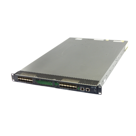
Page 6: Hp 5920Af-24Xg/Hp 5920Af-24Xg Taa Panel Views
"Installing/removing a power supply." The HP 5920AF-24XG and 5920AF-24XG TAA switches also come with the fan tray slots empty. You must install two fan trays for the 5920AF-24XG and 5920AF-24XG TAA for adequate heat dissipation, and their models must be the same. In this figure, two LSVM1FANSC fan trays are installed. For more information about installing and removing the fan tray, see "Installing/removing a fan... -
Page 7: Hp 5900Af-48Xg-4Qsfp+/Hp 5900Af-48Xg-4Qsfp+ Taa Panel Views
(9) ACT LED for the management Ethernet port (10) USB port The HP 5900AF-48XG-4QSFP+ and 5900AF-48XG-4QSFP+ TAA switches come with the power supply slots empty and the filler modules for the slots as accessories. You can install one or two power supplies for the switch as needed. -
Page 8: Hp 5900Af-48Xgt-4Qsfp+ Panel Views
(9) ACT LED for the management Ethernet port (10) USB port The HP 5900AF-48XGT-4QSFP+ switch comes with the power supply slots empty and the filler modules for the slots as accessories. You can install one or two power supplies for the switch as needed. In... -
Page 9: Hp 5900Af-48G-4Xg-2Qsfp+ Panel Views
"Installing/removing a power supply." The HP 5900AF-48XGT-4QSFP+ switch also comes with the fan tray slots empty. You must install two fan trays for the 5900AF-48XGT-4QSFP+ for adequate heat dissipation, and their models must be the same. Figure 1 1, two LSWM1HFANSC fan trays are installed. - Page 10 "Installing/removing a power supply." The HP 5900AF-48G-4XG-2QSFP+ switch also comes with the fan tray slots empty. You must install two fan trays for the 5900AF-48G-4XG-2QSFP+ for adequate heat dissipation, and their models must be the same. In Figure 1 1, two LSWM1FANSC fan trays are installed.
-
Page 11: Preparing For Installation
• to avoid damaging the units. Examining the installation site The HP 5920 and 5900 switches must be used indoors. Mount your switch in a rack and make sure: • Adequate clearance is reserved at the air inlet and exhaust vents for ventilation. -
Page 12: Cleanness
Lasting high relative humidity can cause poor insulation, electricity creepage, mechanical property • change of materials, and metal corrosion. Lasting low relative humidity can cause washer contraction and ESD and bring problems including • loose captive screws and circuit failure. High temperature can accelerate the aging of insulation materials and significantly lower the •... -
Page 13: Laser Safety
Laser safety The HP 5920 and 5900 switches are Class 1 laser devices. WARNING! Do not stare into any fiber port when the switch has power. The laser light emitted from the optical fiber may hurt your eyes. Installation tools •... -
Page 14: Installing The Switch
Keep the tamper-proof seal on a mounting screw on the chassis cover intact, and if you want to open the chassis, contact HP for permission. Otherwise, HP shall not be liable for any consequence caused thereby. Figure 13 Hardware installation flow... -
Page 15: Mounting Bracket And Rack Mounting Rail Kits
Mounting bracket and rack mounting rail kits Every HP 5920 and 5900 switch comes with a pair of mounting brackets and a pair of chassis rails and a pair of slide rails. See Figure 14 Figure Figure 14 1U mounting bracket kit... - Page 16 Each of the HP 5920AF-24XG and 5920AF-24XG TAA switches has one primary grounding point (with a grounding sign) and one auxiliary grounding point, and each of the HP 5900AF-48XG-4QSFP+, 5900AF-48XG-4QSFP+ TAA, 5900AF-48XGT-4QSFP+, and 5900AF-48G-4XG-2QSFP+ switches has one primary grounding point (with a grounding sign) and two auxiliary grounding points. Use the primary grounding point whenever possible.
- Page 17 Figure 19 Identifying the mounting and grounding positions of the HP 5900AF-48G-4XG-2QSFP+ (1) Auxiliary grounding point 2 (2) Rear mounting position (3) Primary grounding point (4) Auxiliary grounding point 1 (5) Front mounting position Attaching the mounting brackets and chassis rails to the chassis...
- Page 18 NOTE: HP recommends that you use the primary grounding point or auxiliary grounding point 1 because the • grounding cable and grounding screw that come with the switch are suitable only for these two grounding points. To use auxiliary grounding point 2 on the HP 5900AF-48XG-4QSFP+, 5900AF-48XG-4QSFP+ TAA, •...
-
Page 19: Attaching The Slide Rails To The Rack
Figure 21 Attaching the front mounting brackets/chassis rails to the chassis Attaching the slide rails to the rack To attach the slide rails to the rack: Identify the rack attachment position for the slide rails. Install cage nuts (user-supplied) in the mounting holes in the rack posts. Align the screw holes in one slide rail with the cage nuts in the rack post on one side, and use screws (user supplied) to attach the slide rail to the rack, as shown in Figure... - Page 20 Wear an ESD-preventive wrist strap and make sure it makes good skin contact and is well grounded. Verify that the mounting brackets and chassis rails have been securely attached to the switch chassis. Verify that the slide rails have been correctly attached to the rear rack posts. Install cage nuts (user-supplied) to the front rack posts and make sure they are at the same level as the slide rails.
-
Page 21: Grounding The Switch
Figure 24 Mounting the switch in the rack (II) Grounding the switch WARNING! Correctly connecting the switch grounding cable is crucial to lightning protection and EMI protection. The power input end of the switch has a noise filter, whose central ground is directly connected to the chassis to form the chassis ground (commonly known as PGND). -
Page 22: Grounding The Switch By Using The Ac Power Cord
(3) Grounding post (4) Grounding strip NOTE: HP recommends that you use the primary grounding point or auxiliary grounding point 1, because the • grounding cable and grounding screw provided with the switch are applicable only to these two grounding points. -
Page 23: Installing/Removing A Fan Tray
Installing/removing a fan tray CAUTION: Every HP 5920 and 5900 switch requires two same direction air flow fan trays to function properly. Do not operate the system with one failed fan tray for more than 24 hours. •... -
Page 24: Removing A Fan Tray
If the captive screw cannot be tightly fastened, check the installation of the fan tray. Figure 27 Installing an LSWM1FANSC/LSWM1FANSCB/LSWM1HFANSC/LSWM1HFANSCB fan tray (to the HP 5900AF-48XG-4QSFP+) Figure 28 Installing an LSVM1FANSC/LSVM1FANSCB fan tray to the HP 5920AF-24XG Removing a fan tray... -
Page 25: Installing/Removing A Power Supply
The switches do not support intermixing of AC and DC power supplies. The HP 5920 and 5900 switches come with both power supply slots empty and the power filler modules as accessories. You can install one or two power supplies for these switches as needed. For more information about the power supplies available for the switches, see "Hot swappable power... - Page 26 CAUTION: Follow the forward inertia of the power supply when inserting it into the chassis, and make sure the • power supply has firm contact with the connectors on the backplane. To prevent damage to the connectors inside the switch chassis, insert the power supply gently. If you •...
-
Page 27: Removing A Power Supply
Removing a power supply CAUTION: If the switch has two power supplies, removing one power supply does not affect the operation of the switch. If the switch has only one power supply, removing the power supply powers off the switch. To remove a 650W AC or DC power supply from the switch: Wear an ESD-preventive wrist strap and make sure it makes good skin contact and is well grounded. -
Page 28: Connecting The Power Cord
Figure 34 Removing the power supply (1) Pivot the latch to the right with your thumb (2) Pull the power supply out Connecting the power cord Connecting the 650W AC power supply Insert the female connector of the AC power cord supplied with the power supply into the power receptacle on the power supply. -
Page 29: Verifying The Installation
The receptacle is foolproof. If you cannot insert the plug into the receptacle, re-orient the plug rather than use excessive force to push it in. Use a cable tie to secure the power cord to the handle of the power supply, as shown in Figure Connect the other end of the power cord to the DC power source. -
Page 30: Accessing The Switch For The First Time
Accessing the switch for the first time Setting up the configuration environment The first time you access the switch you must use a console cable to connect a console terminal, for example, a PC, to the console port on the switch. Figure 37 Connecting the console port to a terminal Connecting the console cable Console cable... -
Page 31: Setting Terminal Parameters
Connect the RJ-45 connector to the console port of the switch. NOTE: Identify the mark on the console port and make sure you are connecting to the correct port. • The serial ports on PCs do not support hot swapping. If the switch has been powered on, connect the •... - Page 32 Figure 40 Setting the serial port used by the HyperTerminal connection Set Bits per second to 9600, Data bits to 8, Parity to None, Stop bits to 1, and Flow control to None, and click OK. Figure 41 Setting the serial port parameters Select File >...
- Page 33 Figure 42 HyperTerminal window On the Settings tab, set the emulation to VT100 and click OK. Figure 43 Setting terminal emulation in Switch Properties dialog box...
-
Page 34: Powering On The Switch
After the startup completes, you can access the CLI to configure the switch. For more information about the configuration commands and CLI, see HP 5920 & 5900 Switch Series Configuration Guide and HP 5920 & 5900 Switch Series Command References. -
Page 35: Setting Up An Irf Fabric
Setting up an IRF fabric You can use HP IRF technology to connect and virtualize HP 5920 and 5900 switches into a large virtual switch called an "IRF fabric" for flattened network topology, and high availability, scalability, and manageability. To set up IRF links between HP 5920 and 5900 switches, use SFP+ ports, 1/10-GE Ethernet ports, or QSFP+ ports. -
Page 36: Planning Irf Fabric Setup
NOTE: As your business grows, you can plug an HP 5920 or 5900 switch into an IRF fabric to increase the switching capacity without any topology change or replacement. Identifying the master switch and planning IRF member IDs Determine which switch you want to use as the master for managing all member switches in the IRF fabric. -
Page 37: Planning Irf Topology And Connections
1/10-GE Ethernet ports or QSFP+ ports. You can bind several 1/10-GE Ethernet ports or QSFP+ ports to an IRF port for increased bandwidth and availability. The HP 5920AF-24XG, and 5920AF-24XG TAA switches can provide 10-GE IRF connections through SFP+ ports. You can bind several SFP+ ports to an IRF port for increased bandwidth and availability. -
Page 38: Identifying Physical Irf Ports On The Member Switches
Every four SFP+ ports form one group. • On the HP 5900AF-48G-4XG-2QSFP+ switch, SFP+ ports numbered 49, 50, 51, and 52 form one group. On the HP 5900AF-48XGT-4QSFP+ switch, the 1/10-GE Ethernet ports are grouped by port •... - Page 39 "QSFP+ port." The following subsections describe several HP recommended IRF connection schemes, and all these schemes use a ring topology. Connecting the IRF member switches in one rack Use short-haul and long-haul SFP+ cables to connect the IRF member switches (four switches in this...
-
Page 40: Configuring Basic Irf Settings
IRF port binding before or after connecting IRF physical ports depending on the software release. • Execute the display irf configuration command to verify the basic IRF settings. For more information about configuring basic IRF settings, see HP 5920 & 5900 Switch Series IRF Configuration Guide. Connecting the physical IRF ports Use SFP+/QSFP+ cables or SFP+/QSFP+ transceiver modules and fibers to connect the IRF member switches as planned. - Page 41 To avoid IP address collision and network problems, configure at least one multi-active detection (MAD) mechanism to detect the presence of multiple identical IRF fabrics and handle collisions. For more HP 5920 & 5900 Switch Series IRF Configuration Guide information about MAD detection, see...
-
Page 42: Maintenance And Troubleshooting
Fan failure CAUTION: Every HP 5920 and 5900 switch requires two same direction air flow fan trays to function properly. Do not operate the system with one failed fan tray for more than 24 hours. • Do not remove the failed fan tray until you are ready for replacing it. -
Page 43: No Terminal Display
No terminal display If the configuration terminal displays nothing when the switch is powered on, verify the following items: The power supply is supplying power to the switch. • The console cable is properly connected. • The console cable has no problem and the terminal settings are correct. •... -
Page 44: Appendix A Technical Specifications
Appendix A Technical specifications 5900AF-48XG-4Q 5920AF-24XG/HP Item SFP+/HP 5900AF-48G-4XG 5900AF-48XGT-4 5920AF-24XG 5900AF-48XG-4Q -2QSFP+ QSFP+ SFP+ TAA 43.6 × 440 × 700 43.6 × 440 × 660 43.6 × 440 × 460 43.6 × 440 × 660 Dimensions (H mm (1.72 × 17.32 ×... - Page 45 5900AF-48XG-4Q 5920AF-24XG/HP Item SFP+/HP 5900AF-48G-4XG 5900AF-48XGT-4 5920AF-24XG 5900AF-48XG-4Q -2QSFP+ QSFP+ SFP+ TAA Single input: Single input: Single AC input: 98 Single input: 334 W 183 W 124 W Dual AC inputs: 343 Dual AC inputs: 200 Dual AC inputs: 115...
-
Page 46: Appendix B Frus And Compatibility Matrixes
Appendix B FRUs and compatibility matrixes This appendix describes the field replaceable units (FRUs) available for the HP 5920 and 5900 Switch Series and their compatibility. All the FRUs in this appendix are hot swappable. Hot swappable power supplies Power supply... - Page 47 Maximum power consumption 19.5 W Docuementation reference HP LSWM1FANSC & LSWM1FANSCB Fan Assemblies Installation LSWM1FANSCB (for the HP 5900AF-48XG-4QSFP+, 5900AF-48XG-4QSFP+ TAA, and 5900AF-48G-4XG-2QSFP+ switches) Fans Two 40 × 40 × 28 mm (1.57 × 1.57 × 1.1 in) fans Fan speed 18500 R.P.M...
- Page 48 Item Specifications LSWM1HFANSCB (for the HP 5900AF-48XGT-4QSFP+ switch) Fans Two 40 × 40 × 56 mm (1.57 × 1.57 × 2.2 in) fans Fan speed 21000 R.P.M Max airflow 33 CFM Front to back Airflow direction (Fans draw air from the network port side to the power module side.)
-
Page 49: Appendix C Ports And Leds
PC running terminal emulation program. Management Ethernet port Every HP 5920 and 5900 switch has one management Ethernet port. You can connect this port to a PC or management station for loading and debugging software or remote management. Table 6 Management Ethernet port specifications... -
Page 50: Sfp+ Port
SFP+ port HP 5920AF-24XG, 5920AF-24XG TAA, 5900AF-48XG-4QSFP+, 5900AF-48XG-4QSFP+ TAA and 5900AF-48G-4XG-2QSFP+ switches have fixed SFP+ ports. You can plug the SFP transceiver modules Table 7, the SFP+ transceiver modules in Table 8, and the SFP+ cables in Table 9 into the SFP+ ports as needed. -
Page 51: Qsfp+ Port
For the most up-to-date list of SFP transceiver modules, consult your HP sales representative or technical support engineer. For the SFP transceiver module specifications, see HP A-Series Switches Transceiver Modules User Guide. The SFP+ cables available for the HP 5920 and 5900 Switch Series are 10 Gbps SFP+ Cu cables, as shown in Figure... - Page 52 HP X140 40G QSFP+ Multimode, 50/125, JG325A 100 m (328.08 ft) MPO SR4 Transceiver Table 11 40G QSFP+ cables available for the HP 5900AF-48XG-4QSFP+, 5900AF-48XG-4QSFP+ TAA, 5900AF-48XGT-4QSFP+, and 5900AF-48G-4XG-2QSFP+ switches Product code Cable description Cable length HP X240 40G QSFP+ QSFP+ 1m Direct Attach Copper JG326A 1 m (3.28 ft)
-
Page 53: 10/100/1000Base-T Autosensing Ethernet Port
(3) SFP+ side pull latch (4) SFP+ module NOTE: To guarantee the functionality of the QSFP+ ports, use only HP QSFP+ transceiver modules and cables. • The QSFP+ transceiver modules and cables available for this switch series are subject to change over •... -
Page 54: Leds
Item Specification • 55 m (180.45 ft) over category-6 unshielded twisted pair cable Transmission medium • 100 m (328.08 ft) over category-6 shielded twisted pair cable transmission distance • 100 m (328.08 ft) over category-6A or above twisted pair cable •... -
Page 55: Management Ethernet Port Leds
Table 16 QSFP+ port LED description LED status Description A transceiver module or cable has been correctly installed. The port has a link and Steady green is operating at 40 Gbps. Flashing green The port is sending or receiving data at 40 Gbps. A transceiver module or cable has been correctly installed. - Page 56 Status Description Steady yellow The port has a link and is operating at 1 Gbps. Flashing yellow The port is sending or receiving data at 1 Gbps. No link is present on the port.
-
Page 57: Appendix D Cooling System
Appendix D Cooling system The cooling system of the HP 5920 and 5900 switches comprises the ventilation holes in the chassis, fan trays, and built-in fans of hot swappable power supplies. To guarantee that this cooling system can effectively work, you must consider the site ventilation design when you plan the installation site for the switches. -
Page 58: 5900Af-48Xgt-4Qsfp+/5900Af-48G-4Xg-2Qsfp+ Cooling System
TAA, 5900AF-48G-4XG-2QSFP+ switches must be the same type: LSWM1FANSC or LSWM1FANSCB. The fan trays in the HP 5900AF-48XGT-4QSFP+ switch must be the same type: LSWM1HFANSC or LSWM1HFANSCB. When LSWM1FANSC/LSWM1HFANSC fan trays are used, cool air flows in through the air vents •... - Page 59 Figure 55 Airflow through the HP 5900AF-48XG-4QSFP+ chassis (with LSWM1FANSC fan trays) (1) Power supply air vents (2) Fan tray air vents (3) Network port-side air vents Figure 56 Airflow through the HP 5900AF-48XG-4QSFP+ chassis (with LSWM1FANSCB fan trays) (1) Power supply air vents...
-
Page 60: Support And Other Resources
Related information Documents To find related documents, browse to the Manuals page of the HP Business Support Center website: http://www.hp.com/support/manuals For related documentation, navigate to the Networking section, and select a networking category. •... -
Page 61: Conventions
Conventions This section describes the conventions used in this documentation set. Command conventions Convention Description Boldface Bold text represents commands and keywords that you enter literally as shown. Italic Italic text represents arguments that you replace with actual values. Square brackets enclose syntax choices (keywords or arguments) that are optional. Braces enclose a set of required syntax choices separated by vertical bars, from which { x | y | ... - Page 62 Network topology icons Represents a generic network device, such as a router, switch, or firewall. Represents a routing-capable device, such as a router or Layer 3 switch. Represents a generic switch, such as a Layer 2 or Layer 3 switch, or a router that supports Layer 2 forwarding and other Layer 2 features.
-
Page 63: Index
A C E F G H I L P R S V HP 5900AF-48XGT-4QSFP+ panel views,4 HP 5920AF-24XG cooling system,53 Accessing the IRF fabric to verify the configuration,36 HP 5920AF-24XG/HP 5920AF-24XG TAA panel views,2 Configuration terminal problems,38 Configuring basic IRF settings,36 Installation...