
Related Manuals for Abit VA-20


Summary of Contents for Abit VA-20
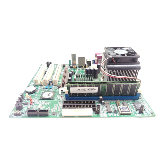
- Page 1 VA-20 ™ ™ ™ AMD Athlon XP / Athlon / Duron Socket 462 System Board User’s Manual Rev. 1.00...
- Page 2 This document contains materials protected under International Copyright Laws. All rights reserved. No part of this manual may be reproduced, transmitted or transcribed without the expressed written permission of the manufacturer and authors of this manual. VA-20...
-
Page 3: Table Of Contents
Table Of Contents Chapter 1. Introduction ............ 1-1 1.1. Features & Specifications............1-1 1.2. Layout Diagram..............1-3 1.3. Jumpers & Connectors Description........1-4 Chapter 2. Hardware Setup..........2-1 2.1. Precautions ................2-1 2.2. Installing the System Board ........... 2-2 2.3. Install CPU and Heatsink ............ - Page 4 3.2.10. Load Optimized Defaults Option ......3-28 3.2.11. Set Password ............3-28 3.2.12. Save & Exit Setup Option........3-29 3.2.13. Exit Without Saving ..........3-29 Chapter 4. Driver Installation .......... 4-1 4.1. Setup Items ................4-2 Appendix A. How to Get Technical Support ..... A-1 VA-20...
-
Page 5: Chapter 1. Introduction
Introduction Chapter 1. Introduction 1.1. Features & Specifications • Supports AMD Socket 462 Athlon XP/Athlon/Duron/Sempron Processor with 400/333/266MHz FSB Chipset • VIA KM400A + VT8237 Memory • Two 184-pin DIMMs • DDR400/333/266/200 un-buffered Memory • Support DDR400 Memory up to 2GB Graphics •... - Page 6 This motherboard is customized for certain system configurations; and may not fit system integration in all DIY ways. Before purchase this product, please check ABIT web site for recommended device listings, or contact sales/tech support people. Specifications and information contained herein are subject to change without notice.
-
Page 7: Layout Diagram
Introduction 1.2. Layout Diagram User’s Manual... -
Page 8: Jumpers & Connectors Description
Additional COM Port Connection Header CPUFAN1/CASFAN1 Fan Power Connectors DIMM1/DIMM2 DDR DIMM Slots FDD1 Floppy Disk Drive Connector IDE1/IDE2 Hard Disk Drive Connectors PANEL1 Front Panel Switch Connection Headers PCI1/PCI2/PCI3 32bit/33MHz PCI Slots SATA1/SATA2 Serial ATA connectors USB3/USB4 Additional USB Port Connection Headers VA-20... -
Page 9: Chapter 2. Hardware Setup
Hardware Setup Chapter 2. Hardware Setup 2.1. Precautions Please pay attention to the following precautions before setting up any hardware. 1. Always switch off the power supply and unplug the power cord from the wall outlet before installing the board or changing any settings. 2. -
Page 10: Installing The System Board
5. Tightens all the screw holes. ATTENTION: To prevent shorting the PCB circuit, please REMOVE the metal studs or spacers if they are already secured on the chassis base and are without mounting-holes on the system board to align with. VA-20... -
Page 11: Install Cpu And Heatsink
Hardware Setup 2.3. Install CPU and Heatsink • Installing a heatsink and cooling fan is necessary for heat to dissipate from your processor. Failing to install these items may result in overheating and processor damage. • The AMD Socket A processor will produce a lot of heat while operating, so you need to use a large heat sink that is especially... - Page 12 & fan assembly is now firmly attached on the CPU socket. 6. Attach the fan connector of Heatsink & Fan Assembly with the fan connector on the motherboard. ATTENTION: Do not forget to set the correct bus frequency and multiple for your processor. VA-20...
-
Page 13: System Memory
Hardware Setup 2.4. System Memory This system board provides two 184-pin DDR DIMM slots for DDR 400/333/266/200 un-buffered memory modules. 2.4.1. Memory Configuration Table DIMM DIMM Module Total Memory 256MB, 512MB, 1GB 256MB ~ 1GB 256MB, 512MB, 1GB 256MB ~ 1GB 256MB ~ 2GB Total System Memory User’s Manual... -
Page 14: Installing And Removing Memory Modules
DIMM module. ATTENTION: As the static electricity can damage the electronic components of the computer or optional modules, make sure you are discharged of static electricity by touching a grounded metal object briefly before starting these procedures. VA-20... -
Page 15: Connectors, Headers, And Switches
Hardware Setup 2.5. Connectors, Headers, and Switches All the connectors, headers and switches mentioned here are depending on your system configuration. Some features you may (or may not) have to connect or to configure depending on the peripherals you have connected. WARNING: Always power off the computer and unplug the AC power cord before adding or removing any peripheral or component. -
Page 16: Fan Connectors (Cpufan1, Casfan1)
CPU fan. • CPUFAN1: Power connector for CPU cooling fan • CASFAN1: Power connector for chassis cooling fan WARNING: These fan connectors are not jumpers. DO NOT place jumper caps on these connectors. VA-20... -
Page 17: Cmos Memory Clearing Header (Jp1)
Hardware Setup 2.5.3. CMOS Memory Clearing Header (JP1) This header uses a jumper cap to clear the CMOS memory. • Pin 1-2 shorted (default): Normal operation. • Pin 2-3 shorted: Clear CMOS memory. ATTENTION: Turn the system power off first (including the +5V standby power) before clearing the CMOS memory. -
Page 18: Bios Write Protection Header (Jp3)
2-10 Chapter 2 2.5.4. BIOS Write Protection Header (JP3) This header uses a jumper cap to protect the BIOS contents from accidentally flashed. • Pin 1-2 shorted (Default): Write Protect Enabled. • Pin 2-3 shorted: Write Protect Disabled. VA-20... -
Page 19: Cpu Fsb Frequency Selector (Jp8, Jp9)
Hardware Setup 2-11 2.5.5. CPU FSB Frequency Selector (JP8, JP9) These headers use jumper caps to select the CPU FSB Frequency. CPU FSB Frequency 100MHz 133MHz 166MHz 200MHz User’s Manual... -
Page 20: Front Panel Switches & Indicators Connection Headers (Panel1)
The mark “+” align to the pin in the figure below stands for positive polarity for the LED connection. Definition Definition HD LED + Message LED + HD LED - Message LED - RESET Power Switch RESET Power Switch Reserved VA-20... -
Page 21: Additional Usb Port Connection Header (Usb3, Usb4)
Hardware Setup 2-13 2.5.7. Additional USB Port Connection Header (USB3, USB4) This header provides 2 additional USB 2.0 ports connection through an USB cable designed for USB 2.0 specifications. Pin Signal Name Function USBPWR Front Panel USB Power USBPWR Front Panel USB Power USB_FP_P0- USB Port 0 Negative Signal USB_FP_P1-... -
Page 22: Front Panel Audio Connection Header (Audio1)
AUD_F_R Right Channel audio signal to Front Panel Right Channel Audio signal to Return from Front AUD_RET_R Panel REVD Reserved No Pin AUD_F_L Left Channel Audio signal to Front Panel Left Channel Audio signal to Return from Front AUD_RET_L Panel VA-20... -
Page 23: Accelerated Graphics Port Slot (Agp1)
Hardware Setup 2-15 2.5.9. Accelerated Graphics Port Slot (AGP1) This slot supports an optional AGP graphics card up to AGP 8X/4X mode. ATTENTION: This motherboard does not support 3.3V AGP cards. Use only 1.5V or 0.8V AGP cards. 2.5.10. Internal Audio Source Connectors (CDIN1, AUXIN1) These connectors connect to the audio output of internal CD-ROM drive or add-on card. -
Page 24: Floppy Disk Drive Connector (Fdd1)
2. Install the other end(s) of ribbon cable into the disk drive connector(s). The colored edge of the ribbon cable should be also aligned with pin-1 of disk drive connector. The endmost connector should be attached to the drive designated as Drive A. VA-20... -
Page 25: Ide Disk Drive Connectors (Ide1, Ide2)
Hardware Setup 2-17 2.5.12. IDE Disk Drive Connectors (IDE1, IDE2) These IDE ports each connects up to two IDE drives at Ultra ATA/100 mode by one 40-pin, 80-conductor, and 3-connector Ultra ATA/66 ribbon cables. Connect the single end (blue connector) at the longer length of ribbon cable to the IDE port on system board, and the other two ends (gray and black connector) at the shorter length of the... - Page 26 2-18 Chapter 2 2.5.13. Additional COM Port Connection Header (COM2) Pin Signal Description Pin Signal Description DCD (Data Carrier RXD (Receive-Data) Detect) TXD (Transfer-Data) (Data-Terminal-Ready) DSR (Data-Set-Ready) CTS (Clear-to-Send) (Request-to-Send) RI (Ring-Indicator) NC (No Connected) VA-20...
-
Page 27: Serial Ata Connectors (Sata1, Sata2)
Hardware Setup 2-19 2.5.14. Serial ATA connectors (SATA1, SATA2) These connectors are provided to attach one Serial ATA device at each channel via Serial ATA cable. This motherboard also provides RAID 0 and RAID 1 configuration for Serial ATA hard drives through the VIA VT8237 chipset. User’s Manual... -
Page 28: External I/O Panel
Mic In: Connects to the plug from external microphone. Line In: Connects to the line out from external audio sources. Line Out: Connects to the front left and front right channel in the 5.1-channel or regular 2-channel audio system. VA-20... -
Page 29: Chapter 3. Bios Setup
BIOS Setup Chapter 3. BIOS Setup 3.1. About the Setup Utility The computer uses the latest Award BIOS with support for Windows Plug and Play. The CMOS chip on the motherboard contains the ROM setup instructions for configuring the motherboard BIOS. The BIOS (Basic Input and Output System) Setup Utility displays the system’s configuration status and provides you with options to set system parameters. -
Page 30: Entering The Setup Utility
Modifies the selected field’s values +/-/PU/PD Saves the current configuration and exits setup Displays a screen that describes all key functions Loads previously saved values to CMOS Loads a minimum configuration for troubleshooting Loads an optimum set of values for peak performance VA-20... -
Page 31: Updating The Bios
BIOS Setup 3.1.3. Updating the BIOS You can download and install updated BIOS for this motherboard from the manufacturer’s Web site. New BIOS provides support for new peripherals, improvements in performance, or fixes for known bugs. Install new BIOS as follows: 1. -
Page 32: Using Bios
Date and Time The Date and Time items show the current date and time on the computer. If you are running a Windows OS, these items are automatically updated whenever you make changes to the Windows Date and Time Properties utility. VA-20... - Page 33 BIOS Setup IDE Devices (None) Your computer has two IDE channels (Primary and Secondary) and each channel can be installed with one or two devices (Master and Slave). Use these items to configure each device on the IDE channel. Press <Enter> to display the IDE submenu: IDE HDD Auto-Detection Press <Enter>...
- Page 34 You can use this item to select which types of errors in the POST are sufficient to halt the system. Base Memory, Extended Memory, and Total Memory These items are automatically detected by the system at start up time. These are display-only fields. You cannot make changes to these fields. VA-20...
-
Page 35: Advanced Bios Features
BIOS Setup 3.2.2. Advanced BIOS Features This option defines advanced information about your system. ATA 66/100 IDE Cable Msg. (Enabled) This item enables or disables the display of the ATA 66/100 Cable MSG. Quick Power On Self Test (Enabled) Enable this item to shorten the power on testing (POST) and have your system start up faster. - Page 36 Setup Utility. APIC Mode (Enabled) This item allows you to enable or disable the APIC (Advanced Programmable Interrupt Controller) mode. APIC provides symmetric multi-processing (SMP) for systems, allowing support for up to 60 processors. VA-20...
-
Page 37: Advanced Chipset Features
BIOS Setup OS Select For DRAM > 64 MB (Non-OS2) This item is only required if you have installed more than 64 MB of memory and you are running the OS/2 operating system. Otherwise, leave this item at the default. HDD S.M.A.R.T Capability (Disabled) The S.M.A.R.T. - Page 38 If you disable this item, you can use the following three items to manually set the timing parameters for the system memory. VA-20...
- Page 39 BIOS Setup 3-11 DRAM CAS Latency (2.5): Enables you to select the CAS latency time in HCLKs of 2/2 or 3/3. The value is set at the factory depending on the DRAM installed. Do not change the values in this field unless you change specifications of the installed DRAM or the installed CPU.
- Page 40 AGP cards need stronger than normal driving current in order to operate. We recommend that you set this item to the default. AGP Driving Value: When AGP Driving Control is set to Manual, use this item to set the AGP current driving value. VA-20...
- Page 41 BIOS Setup 3-13 AGP Fast Write (Disabled) This item lets you enable or disable the caching of display data for the video memory of the processor. Enabling this item can greatly improve the display speed. Disable this item if your graphics display card does not support this feature. AGP Master 1 WS Write: This item implements a single delay when writing to the AGP Bus.
-
Page 42: Integrated Peripherals
3-14 Chapter 3 3.2.4. Integrated Peripherals These options display items that define the operation of peripheral components on the system’s input/output ports. VIA OnChip IDE Device Scroll to this item and press <Enter> to view the following screen: VA-20... - Page 43 BIOS Setup 3-15 OnChip SATA (Enabled) This option allows you enable or disable the onboard Serial ATA device. On-Chip IDE Channel 0/1 (Enabled) Use these items to enable or disable the PCI IDE channels that are integrated on the motherboard. IDE Prefetch Mode (Enabled) The onboard IDE drive interfaces supports IDE prefetching, for faster drive access.
- Page 44 USB 2.0 Support (Enabled) Enable this item if want to use the USB 2.0. USB Legacy Support (Enabled) This item allows the BIOS to interact with a USB keyboard or mouse to work with MS-DOS based utilities and non-Windows modes. VA-20...
- Page 45 BIOS Setup 3-17 USB Mouse Support (Disabled) Enable this item if you plan to use a mouse connected through the USB port in a legacy operating system (such as DOS) that does not support Plug and Play. Press <Esc> to return to the Integrated Peripherals screen. Onboard LAN Device (Enabled) Enables and disables the onboard LAN chip.
- Page 46 Init Display First (PCI Slot) Use this item to specify whether your graphics adapter is installed in one of the PCI slots or is integrated on the motherboard. Onboard 1394 Device (Enabled) Enables and disables the onboard IEEE 1394 controller. VA-20...
-
Page 47: Power Management Setup
BIOS Setup 3-19 3.2.5. Power Management Setup This option lets you control system power management. The system has various power-saving modes including powering down the hard disk, turning off the video, suspending to RAM, and software power down that allows the system to be automatically resumed by certain events. - Page 48 If the item is set to Instant-Off, then the power button causes a software power down. If the item is set to Delay 4 Sec. then you have to hold the power button down for four seconds to cause a software power down. VA-20...
- Page 49 BIOS Setup 3-21 Run VGABIOS if S3 Resume (Auto) This item allows the system to initialize the VGA BIOS from S3 (Suspend to RAM) sleep state. PWRON After PWR-Fail (Off) This item enables your computer to automatically restart to its last operating status after power returns from a power failure.
- Page 50 When set to Enabled, additional fields become available and you can set the date (day of the month), hour, minute and second to turn on your system. When set to 0 (zero) for the day of the month, the alarm will power on your system every day at the specified time. VA-20...
- Page 51 BIOS Setup 3-23 IRQs Activity Monitoring This screen enables you to set IRQs that will resume the system from a power saving mode. Set any IRQ to Enabled to allow activity at the IRQ to wake up the system from a power saving mode.
-
Page 52: Pnp/Pci Configurations
Manual, and then opening up the IRQ Resources submenu. In the IRQ Resources submenu, if you assign an IRQ to Legacy ISA, then that Interrupt Request Line is reserved for a legacy ISA expansion card. Press <Esc> to close the IRQ Resources submenu. VA-20... - Page 53 BIOS Setup 3-25 IRQ Resources The submenu allows you to individually assign an interrupt type for interrupts IRQ-3 to IRQ-15. In the IRQ Resources submenu, if you assign an IRQ to Legacy ISA, then that Interrupt Request Line is reserved for a legacy ISA expansion card. Press <Esc> to close the IRQ Resources submenu.
-
Page 54: Pc Health Status
These items allow end users and technicians to monitor data provided by the BIOS on this motherboard. You cannot make changes to these fields. • CPU Vcore • Voltage Battery • Current System Temp • Current CPU Temp • CPU FAN Speed • CAS FAN Speed VA-20... -
Page 55: Frequency/Voltage Control
BIOS Setup 3-27 3.2.8. Frequency/Voltage Control This item enables you to set the clock speed and system bus for your system. The clock speed and system bus are determined by the kind of processor you have installed in your system. DIMM Voltage Adjust (2.58V) This item adjusts the voltage delivered to the DIMM memory. -
Page 56: Load Fail-Safe Defaults Option
BIOS Setup. If you have selected “Setup” at “Security Option” from “BIOS Features Setup” menu, you will be prompted for the password only when you enter BIOS Setup. VA-20... -
Page 57: Save & Exit Setup Option
BIOS Setup 3-29 Supervisor Password has higher priority than User Password. You can use Supervisor Password when booting the system or entering BIOS Setup to modify all settings. Also you can use User Password when booting the system or entering BIOS Setup but can not modify any setting if Supervisor Password is enabled. - Page 58 3-30 Chapter 3 VA-20...
-
Page 59: Chapter 4. Driver Installation
Driver Installation Chapter 4. Driver Installation All the necessary drivers are included within the Drivers & Utilities CD that came packaged with your board. The display shown in the following figure should appear after inserting this CD into your CD-ROM drive, if not, enter [My Computer] [CD-ROM] Drive double click [autorun.exe]. -
Page 60: Setup Items
• Utility Click to enter the sub-screen for installing software like Acrobat Reader, DirectX, and LoFormat utility. • ABIT Utility Click to enter the sub-screen to install FlashMenu (BIOS Update Utility) for updating BIOS. • Browse CD Browse the contents of this CD-ROM. -
Page 61: Appendix A. How To Get Technical Support
Also please make sure you have the latest drivers from your peripheral cards makers! 3. Check the ABIT Technical Terms Guide and FAQ on our Website. We are trying to expand and make the FAQs more helpful and information rich. Let us know if you have any suggestions. - Page 62 They should have reasonable return or refund policies. How they serve you is also a good reference for your next purchase. 6. Contacting ABIT. If you feel that you need to contact ABIT directly you can send email to the ABIT technical support department. First, please contact the support team for the branch office closest to you.
- Page 63 Unit 3, 24-26 Boulton Road, Stevenage, Herts SG1 4QX, UK Tel: 44-1438-228888 Fax: 44-1438-226333 E-mail: sales@abitcomputer.co.uk Germany and Benelux AMOR Computer B.V. (ABIT's European Office) Jan van Riebeeckweg 15, 5928LG, Venlo, (Belgium, Netherlands, Luxembourg), France, The Netherlands Tel: 31-77-3204428 Italy, Spain, Portugal,...
-
Page 64: Technical Support Form
Appendix A Technical Support Form Company Name: Phone Number: Contact Person: Fax Number: E-mail Address: Model BIOS ID # Motherboard Model No. DRIVER REV OS/Application Hardware Name Brand Specifications IDE1 IDE2 IDE1 CD-ROM-Drive IDE2 System Memory ADD-ON CARD Problem Description: VA-20...