Table of Contents
Advertisement
Quick Links
Copyright and Warranty Notice
The information in this document is subject to change without notice and does not
represent a commitment on part of the vendor, who assumes no liability or responsibility
for any errors that may appear in this manual.
No warranty or representation, either expressed or implied, is made with respect to the
quality, accuracy or fitness for any particular part of this document. In no event shall the
manufacturer be liable for direct, indirect, special, incidental or consequential damages
arising from any defect or error in this manual or product.
Product names appearing in this manual are for identification purpose only and
trademarks and product names or brand names appearing in this document are the
property of their respective owners.
This document contains materials protected under International Copyright Laws. All
rights reserved. No part of this manual may be reproduced, transmitted or transcribed
without the expressed written permission of the manufacturer and authors of this manual.
If you do not properly set the motherboard settings, causing the motherboard to
malfunction or fail, we cannot guarantee any responsibility.
Advertisement
Table of Contents

Related Manuals for Abit SE6


Summary of Contents for Abit SE6
- Page 1 Copyright and Warranty Notice The information in this document is subject to change without notice and does not represent a commitment on part of the vendor, who assumes no liability or responsibility for any errors that may appear in this manual. No warranty or representation, either expressed or implied, is made with respect to the quality, accuracy or fitness for any particular part of this document.
-
Page 3: Table Of Contents
SE6 Motherboard User’s Manual Index CHAPTER 1. INTRODUCTION OF SE6 FEATURES .........1-1 1-1............1-1 EATURES OF OTHERBOARD 1-2..................1-1 PECIFICATIONS 1-3...................1-2 ACKAGE 1-4..................1-3 AYOUT IAGRAM 1-5..............1-4 YSTEM LOCK IAGRAM CHAPTER 2. INSTALLING THE MOTHERBOARD........2-1 2-1........2-1 NSTALLING THE... - Page 4 ® APPENDIX F. INSTALLING THE AUDIO DRIVER FOR THE WINDOWS NT 4.0 SERVER/WORKSTATION ® APPENDIX G. ATA INSTALLATION UTILITY FOR THE WINDOWS NT 4.0 SERVER/WORKSTATION ® APPENDIX H. INF INSTALLATION UTILITY FOR THE WINDOWS 2000 ® APPENDIX I. INSTALLING THE VGA DRIVER FOR THE WINDOWS 2000 ®...
-
Page 5: Chapter 1. Introduction Of Se6 Features
Module (AIMM). AIMM is a lower cost alternative to a video card. With 2 USB ports as well as capability of expanding to 4 USB slots, the SE6 meets future USB demands. A Communication / Network Riser Slot (CNR Slot) is found on the SE6. The CNR Slot provides audio, modem and network connectivity. -
Page 6: Package List
# # # # Specifications and information contained in this manual are subject to change without notice. 1-3. Package List Check the following list. If there is any items damaged or missing, please contact your local dealer. $ (1) SE6 Motherboard % DB-20: Debug card (optional) $ (1) Ribbon cable for master and slave Ultra... -
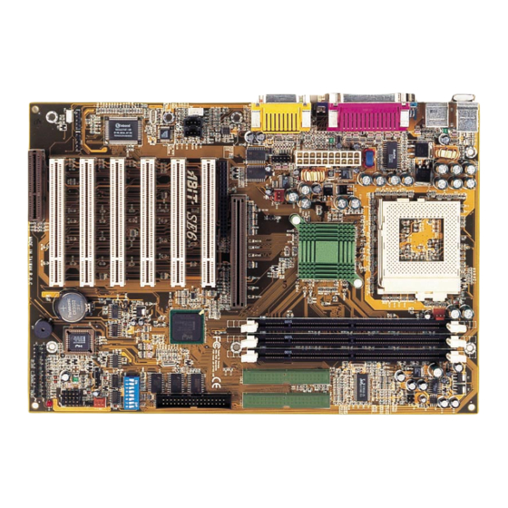
Page 7: Layout Diagram
Introduction of SE6 Features 1-4. Layout Diagram Figure 1-1. SE6 Motherboard component location User’s Manual... -
Page 8: The System Block Diagram
Chapter1 1-5. The System Block Diagram Figure 1-2. System diagram of the INTEL 815E Chipset... -
Page 9: Chapter 2. Installing The Motherboard
Installing the Motherboard Chapter 2. Installing the Motherboard This SE6 motherboard not only provides all standard equipment for classic personal computers, but also provides great flexibility for meeting future upgrade demands. This chapter will introduce step by step all of the standard equipment and will also present, as completely as possible, future upgrade capabilities. -
Page 10: Installation Of The Pentium Iii Cpu
Chapter2 Note: If the motherboard has mounting holes, but they don’t line up with the holes on the base and there are no slots to attach the spacers, do not despair, you can still attach the spacers to the mounting holes. Just cut the bottom portion of the spacers (the spacers may be a little hard to cut, so mind your fingers). -
Page 11: Connectors, Headers And Switches
Installing the Motherboard Step 1. Before you install the memory module, please place the computer power switch in the “OFF” position and disconnect the AC power cord. Step 2. Remove the computer’s chassis cover. Step 3. Before touching any electronic components, make sure you first touch an unpainted, grounded metal object to discharge any static electricity stored on your clothing or body. - Page 12 Chapter2 Figure 2-5. All Connectors and Headers for the SE6 First, Let’s look at the headers that the SE6 uses, and what their functions are.
- Page 13 Installing the Motherboard damaged overheating. keep computer’s internal temperature steady and not (1) ATXPR1: ATX Power Input Connector too high, connecting the chassis fan is imperative. Note: Watch the pin position and the orientation (3) IR1: IR Header (Infrared) If the power supply connectors are not properly attached to the ATXPR1 power supply, the power supply or add-on cards may be damaged.
- Page 14 Chapter2 utility or other similar utilities. control the bus, an arbitration procedure decides which master gets priority. Note: Watch the pin position and the orientation Note: Watch the pin position and the orientation. (5) CNR Slot: Communication Network Riser Slot (7) JP3 Header (RT2 Thermistor): This slot is used for an optional CNR with the main objective of reducing the baseline...
- Page 15 Installing the Motherboard by attaching an optional USB port expansion (10) CD1: Internal CD-ROM Drive Audio cable. There are three ways to use this Cable Header additional USB port: 12 14 16 18 20 USB3 8 10 USB2 13 15 17 19 1.
- Page 16 Chapter2 you to force CPU clock to be adjusted by Note: Before you clear the CMOS, you have SW3-SW4: to first turn the power off (including the +5V standby power). Otherwise, your system may SW3-SW4 “ON”: 66MHz work abnormally or malfunction. SW3 “OFF”, SW4 “ON”: 100MHz SW3-SW4 “OFF”: 133MHz (13) AGP &...
- Page 17 Installing the Motherboard PN1 and PN2 are for switches and indicators of PN2 (Pin 1-2): Hardware Reset Switch the chassis’ front panel. There are several Header functions that come from these two headers. You have to watch the pin position and the Attach the cable from the case’s front panel orientation, cause...
- Page 18 PIN 14 No connection disk drive on their computer system. The connector attached to the longer length of Now let’s see the I/O connectors that the SE6 ribbon should be attached to the motherboard uses, and what their functions are. connector.
- Page 19 Please Figure 2-9. SE6 back panel connectors refer to the hard disk drive user’s manual. Figure 2-9 shows the SE6 back panel connectors. Note: A red mark on a wire typically These connectors are for connection to outside designates the location of pin 1.
- Page 20 2-12 Chapter2 (21) Serial Port COM1 Connector (25) COM2 Header This motherboard provides two COM ports. You can connect an external modem, mouse or other devices that support this communication protocol to this connector. You can decide which external device you want to connect to COM1.
-
Page 21: Chapter 3. Introducing The Bios
BIOS Setup Chapter 3. Introducing the BIOS The BIOS is a program located on a Flash Memory chip on the motherboard. This program will not be lost when you turn the computer off. This program is also referred to as the boot program. It is the only channel the hardware circuit has to communicate with the operating system. -
Page 22: Cpu Setup [Soft Menu ™ Iii]
Chapter3 ! Press Esc to quit the BIOS Setup. ! Press ↑ ↑ ↑ ↑ ↓ ↓ ↓ ↓ ← ← ← ← → → → → (up, down, left, right) to choose, in the main menu, the option you want to confirm or to modify. - Page 23 BIOS Setup ® ™ Pentium III and Celeron MMX processors, you can choose the following settings: 300 (66) 333 (66) 366 (66) 400 (66) 433 (66) 466(66) 500 (66) 500 (100) 533 (66) 533 (133) 550 (100) 566 (66) 600 (66) 600 (100) 600 (133) 633 (66)
- Page 24 Chapter3 System Memory Frequency: You can select the operating frequency for the main system memory. There are three options available: 100MHz, 133MHz, and Auto. The default setting is 100MHz. Speed Error Hold: The default setting is “Disabled”. If you change the setting to “Enabled” when the CPU speed setting is wrong, the system will hold.
-
Page 25: Standard Cmos Features Setup Menu
BIOS Setup 3-2. Standard CMOS Features Setup Menu This section contains the basic configuration parameters of the BIOS. These parameters include date, hour, VGA card, FDD and HDD settings. Figure 3-3. Standard CMOS Setup Screen Shot Date (mm:dd:yy): You can set the date in this item: month (mm), date (dd) and year (yy). Time (hh:mm:ss): You can set the time in this item: hour (hh), minute (mm) and second (ss). - Page 26 Chapter3 Note 1: A new IDE HDD must be first formatted, otherwise it can not read/write. The basic step in using a HDD is to make a HDD low-level format, then run FDISK, and then FORMAT the drive. Most current HDDs have already been subjected to low-level format at the factory, so you can probably skip this operation.
- Page 27 BIOS Setup Head: This is the tiny electromagnetic coil and metal pole used to create and read back the magnetic patterns on the disk (also called the read/write head). You can configure the number of read/write heads. The minimum number you can enter is 0, the maximum number you can enter is 255. Precomp: The minimum number you can enter is 0, the maximum number you can enter is 65536.
-
Page 28: Advanced Bios Features Setup Menu
Chapter3 3-3. Advanced BIOS Features Setup Menu With each item, you can press <Enter> at any time to display all the options for that item. Attention: Advanced BIOS Features Setup Menu has already been set for maximum operation. If you do not really understand each of the options in this menu, we recommend you use the default values. - Page 29 BIOS Setup ® ® ® with Intel Pentium III processors. When you install a Pentium III processor into your motherboard, and when your system boots-up then this item will show up in BIOS. Two items will be available: Enabled and Disabled. When you choose Enabled, the specific program can read your processor's serial number.
- Page 30 3-10 Chapter3 Off: At boot up, the Numeric Keypad is in cursor control mode. Typematic Rate Setting: This item allows you to adjust the keystroke repeat rate. When set to Enabled, you can set the two keyboard typematic controls that follow (Typematic Rate and Typematic Rate Delay). If this item is set to Disabled, the BIOS will use the default setting.
-
Page 31: Advanced Chipset Features Setup Menu
BIOS Setup 3-11 Delay IDE Initial (Secs): This item is used to support some old models or special types of hard disks or CD-ROMs. They may need a longer amount of time to initialize and prepare for activation. Since the BIOS may not detect those kinds of devices during system booting. - Page 32 3-12 Chapter3 SDRAM Cycle Time Tras/Trc: Two options are available: 5/7 and 7/9. The default setting is 7/9. This item controls the number of SDRAM clocks (SCLKs) used per access cycle. SDRAM RAS-to-CAS Delay Two options are available: 2 and 3. The default setting is 3. This item lets you insert a timing delay between the CAS and RAS strobe signals, used when DRAM is written to, read from, or refreshed.
- Page 33 BIOS Setup 3-13 AGP Graphics Aperture Size: Two options are available: 32M ) 64M. The default setting is 64M. This option specifies the amount of system memory that can be used by the AGP device. The aperture is a portion of the PCI memory address range dedicated for graphics memory address space.
-
Page 34: Integrated Peripherals
3-14 Chapter3 3-5. Integrated Peripherals In this menu, you can change the onboard I/O device, I/O port address and other hardware settings. Figure 3-7. Integrated Peripherals Menu Screen Onboard IDE-1 Controller: The onboard IDE 1 controller can be set as Enabled or Disabled. The default setting is Enabled. The integrated peripheral controller contains an IDE interface with support for two IDE channels. - Page 35 BIOS Setup 3-15 Auto: If your hard drive and your system software both support Ultra DMA, select Auto to enable BIOS support. Disabled: If you encounter a problem in using Ultra DMA devices, you can try to disable this item. Onboard IDE-2 Controller: Description is same as the Onboard IDE-1 Controller.
- Page 36 3-16 Chapter3 Power On Function: This item allows you to select which way you want your system to power on. Seven items are available: Password ) Hot Key ) Mouse Left ) Mouse Right ) Any Key ) Button Only ) Keyboard 98. Default setting is Button Only.
- Page 37 BIOS Setup 3-17 Two options are available: Full and Half. The default setting is Half. This item lets you choose the operation mode for your IR KIT. Some IR device only can work at half duplex mode. Refer to your IR KIT user's guide to find out which setting is correct.
-
Page 38: Power Management Setup Menu
3-18 Chapter3 3-6. Power Management Setup Menu The difference between Green PCs and traditional computers is that Green PCs have a power management feature. With this feature, when the computer is powered on but inactive, the power consumption is reduced in order to save energy. When the computer operates normally, it is in Normal mode. - Page 39 BIOS Setup 3-19 http://www.teleport.com/~acpi/acpihtml/home.htm ACPI requires an ACPI-aware operating system. ACPI features include: ! Plug and Play (including bus and device enumeration) and APM functionality normally contained in the BIOS. ! Power management control of individual devices, add-in cards (some add-in cards may require an ACPI-aware driver), video displays, and hard disk drives.
- Page 40 3-20 Chapter3 The S1 (POS) State (POS means Power On Suspend): While the system is in the S1 sleeping state, its behavior is as described below: ! The processor is not executing instructions. The processor’s complex context is maintained. ! Dynamic RAM context is maintained. ! Power Resources are in a state compatible with the system S1 state.
- Page 41 BIOS Setup 3-21 User Define: “User Define” defines the delay for accessing the power modes. Suspend Mode: Disabled ) 1 Min ) 2 Min ) 4 Min ) 8 Min ) 12 Min ) 20 Min ) 30 Min ) 40 Min ) 1 Hour. The default setting is Disabled. HDD Power Down: Disabled ) 1 Min ) 2 Min ) 3 Min ) 4 Min ) 5 Min ) 6 Min ) 7 Min ) 8 Min ) 9 Hour ) 10 Min ) 11 Min ) 12 Min ) 13 Min ) 14 Min ) 15 Min.
- Page 42 3-22 Chapter3 up your computer by PCI devices. For instance, if you had installed a PCI LAN card with Wake-Up on LAN capability, then you could wake-up your computer from another computer via a network by sending a wake-up frame signal. This feature also allows the PCI card built-in hardware function to support the wake up function without special cables connected to the motherboard.
-
Page 43: Pnp/Pci Configurations
BIOS Setup 3-23 3-7. PnP/PCI Configurations This section describes configuring the PCI bus system. PCI, or Personal Computer Interconnect, is a system which allows I/O devices to operate at speeds nearing the speed the CPU itself uses when communicating with its own special components. This section covers some very technical items and it is strongly recommended that only experienced users should make any changes to the default settings. - Page 44 3-24 Chapter3 Figure 3-10. IRQ Resources Setup Screen Shot PCI /VGA Palette Snoop: This option allows the BIOS to preview VGA Status, and to modify the information delivered from the Feature Connector of the VGA card to the MPEG Card. This option can solve the display inversion to black after you have used the MPEG card.
-
Page 45: Pc Health Status
BIOS Setup 3-25 PCI slot 1 PCI slot 2 Signals PCI slot 3 PCI slot 4 PCI slot 5 PCI slot 6 INT Pin 1 Assignment INT A INT B INT C INT D INT Pin 2 Assignment INT B INT C INT D INT A... -
Page 46: Load Fail-Safe Defaults
3-26 Chapter3 3-9. Load Fail-Safe Defaults Figure 3-12. Load Fail-Safe Defaults Screen Shot When you press <Enter> on this item you get a confirmation dialog box with a message similar to: Load Fail-Safe Defaults (Y/N) ? N Pressing “Y” loads the BIOS default values for the most stable, minimal-performance system operations. 3-10. -
Page 47: Set Password
BIOS Setup 3-27 3-11. Set Password Figure 3-14. Set Password Screen Shot Set Password: You can enter but do not have the right to change the options of the setup menus. When you select this function, the following message will appear at the center of the screen to assist you in creating a password. -
Page 48: Save & Exit Setup
3-28 Chapter3 3-12. Save & Exit Setup Figure 3-16. Save & Exit Setup Screen Shot Pressing <Enter> on this item asks for confirmation: Save to CMOS and EXIT (Y/N)? Y Pressing “Y” stores the selections made in the menus in CMOS - a special section of memory that stays on after you turn your system off. -
Page 49: Appendix A. Inf Installation Utility For Windows
98 SE installation, operations and settings, please refer to your ® ® Windows 98 SE user's manual or other resources provided by Microsoft Corporation. Insert the SE6 CD-Title into your CD-ROM drive, should execute program automatically. If not, you can go to the CD location and execute the execution file at the main directory of this CD-Title. - Page 50 Appendix A The Welcome screen appears. Click “Next>” to The install shield is now loading. go on. Choose “Yes, I want to restart my computer The License screen appears. Read it and click now”, and click “Finish” to end the installation. “Yes”...
-
Page 51: Appendix B. Installing The Vga Driver For Windows
98 SE Now we will show you how to install the VGA driver to your Windows ® 98 SE operating system in this section. Insert the SE6 CD-Title into your CD-ROM drive, should execute program automatically. If not, you can go to the CD location and execute the execution file at the main directory of this CD-Title. - Page 52 Appendix B The License screen appears. Click “Yes” to go The install shield is now loading. Choose “Yes, I want to restart my computer now”, and click “Finish” to end the installation.
-
Page 53: Appendix C. Installing The Audio Driver For Windows
CD-Title. After it has been executed you will see the screen below. Move the cursor to “RealTek ALC100/200(for SE6)” and click on it to go on. Move the cursor to “Drivers” and click on it to go on. - Page 54 Appendix C The Welcome screen appears. Click “Next>” to Choose “Yes, I want to restart my computer go on. now”, and click “Finish” to end the installation. The install shield is now loading. Click “OK” to go on. Click “Go!” to go on.
-
Page 55: Appendix D. Ata Installation Utility For Windows
ATA Installation Utility for Windows 98 SE ® Appendix D. ATA Installation Utility for Windows In this section we will detail the Ultra ATA installation procedure. Insert the SE6 CD-Title into your CD-ROM drive, should execute program automatically. If not, you can go to the CD location and execute the execution file at the main directory of this CD-Title. - Page 56 Appendix D The License screen appears. Read it and click Choose “Yes, I want to restart my computer “Yes” to go on. now”, and click “Finish” to end the installation. Now you can choose the folder for the destination location you want to install the driver.
-
Page 57: Appendix E. Installing The Vga Driver For The Windows
NT 4.0 Server/Workstation operating system, you don't need to install the INF ® Installation Utility. But you have to install the Windows NT 4.0 Service Pack 4 (or latest version) first. Insert the SE6 CD-Title into your CD-ROM drive, should execute program automatically. - Page 58 Appendix E The Welcome screen appears. Click “Next>” to Choose “Yes, I want to restart my computer go on. now”, and click “Finish” to end the installation. The License screen appears. Click “Yes” to go The install shield is now loading.
- Page 59 CD-Title. After it has been executed you will see the screen below. Move the cursor to “RealTek ALC100/200(for SE6)” and click on it to go on. Move the cursor to “Drivers” and click on it to go on.
- Page 60 Appendix F Choose the language for this installation. Choose “Yes, I want to restart my computer now”, and click “Finish” to end the installation. The Welcome screen appears. Click “Next>” to go on. The install shield is now loading.
- Page 61 In this section we will show you how to install the ATA Utility to your Windows ® NT 4.0 ® Server/Workstation operating system. All screen shot are from Windows NT 4.0 server version. Insert the SE6 CD-Title into your CD-ROM drive, should execute program automatically. If not, you can go to the CD location and execute the execution file at the main directory of this CD-Title.
- Page 62 Appendix G The License screen appears. Read it and click The install shield is now loading. “Yes” to go on. Choose “Yes, I want to restart my computer Now you can choose the folder for the now”, and click “Finish” to end the installation. destination location you want to install the driver.
- Page 63 2000, please refer to your ® ® Windows 2000 user's manual or other resources provided by Microsoft Corporation. Insert the SE6 CD-Title into your CD-ROM drive, should execute program automatically. If not, you can go to the CD location and execute the execution file at the main directory of this CD-Title.
- Page 64 Appendix H Click “Yes” to go on. The license screen appears. Read it and click “Yes” to go on. Choose “Yes, I want to restart my computer now”, and click “Finish” to end the installation. Read this “Readme Information” and click “Next>”...
-
Page 65: Windows 2000
® Installing the VGA Driver for the Windows 2000 Appendix I. Installing the VGA Driver for the ® Windows 2000 In this section we will show you how to install the VGA Driver to your Windows ® 2000 operating system. ®... - Page 66 Appendix I Select “Have Disk…”. The Upgrade Device Driver Wizard screen appears. Click “Next>” to go on. Insert the SE6 CD-Title and click “OK”. The path for this VGA driver is located at D:\DRIVERS\vga\win2000\Win2000 (D:\ is the CD-ROM letter). The Wizard will ask you if you would like the computer to select a suitable driver for you or if you would like to manually select one.
- Page 67 ® Installing the VGA Driver for the Windows 2000 The Wizard is ready to install the driver. Click “Next>” to go on. The Wizard is now finishing the driver installation. Click “Finish” installation. User’s Manual...
- Page 68 Appendix I...
-
Page 69: Windows 2000
CD-Title. After it has been executed you will see the screen below. Move the cursor to “RealTek ALC100/200(for SE6)” and click on it to go on. Move the cursor to “Drivers” and click on it to go on. - Page 70 Appendix J Choose the language for this installation. Click “Yes” to go on. The Welcome screen appears. Click “Next>” to go on. Choose “Yes, I want to restart my computer now”, and click “Finish” to end the installation. The install shield is now loading.
- Page 71 In this section we will show you how to install the ATA Utility to your Windows ® 2000 operating system. ® All screen shot are from Windows 2000 version. Insert the SE6 CD-Title into your CD-ROM drive, should execute program automatically. If not, you can go to the CD location and execute the execution file at the main directory of this CD-Title.
- Page 72 Appendix K The License screen appears. Read it and click Choose “Yes, I want to restart my computer “Yes” to go on. now”, and click “Finish” to end the installation. Now you can choose the folder for the destination location you want to install the driver.
- Page 73 BIOS Flashing User Instructions Appendix L. BIOS Flashing User Instructions When your motherboard needs to be upgraded with new features or there are some compatibility problems in the BIOS that need to be fixed, you will need this BIOS flash utility. Award Software had made this utility to be easily flashed by you.
- Page 74 .bin names. Please read the BIOS file description before you download For example, if you want to update the SE6 BIOS, please follow the procedures described below. Step 1. Please visit our Website (www.abit.com.tw) and download the following files: ABITFAE.BAT, AWDFLASH.EXE and the SE6’s newest BIOS file -- SE6_MJ.EXE for example.
-
Page 75: The Winbond Hardware Doctor Utility
Hardware Monitoring Function (Installing the Winbond Hardware Doctor Utility) Appendix M. Hardware Monitoring Function (Installing the Winbond Hardware Doctor Utility) Winbond Hardware Doctor is a self-diagnostic system for PCs and must be used with the Winbond chipset: W83627HF IC series products. It protects PC hardware by monitoring several critical items including power supply voltages, CPU &... - Page 76 Appendix M Ignore: ignore warning message of the item, but it will pop up again when an error of the same item reoccurs. Disable: The chosen item will be no longer monitored thereafter, unless you activate it in the “Configuration” page.
- Page 77 Installation Guide for Suspend to RAM Appendix N. Installation Guide for Suspend to RAM Suspend To RAM (STR) is a cost-effective, optimal implementation of the ACPI 1.0 specification. The ACPI specification defines the S3 sleep state, in which all system context is lost except system memory. CPU, cache, and chip set context are lost in this state.
- Page 78 Appendix N There are two ways to put your system into STR mode: Method 1: Select “Stand by” in the “Shut Down Windows” area. Select “Advanced”, and then set the “Power Buttons” to “Standby”. Click “Start” in the Windows Tools Bar, and then select “Shut Down…”...
- Page 79 Fax this form to your dealer or to the company where you bought the hardware or your nearest ABIT branch office in order to benefit from our technical support. (You can refer to the examples given below) Example 1: With a system including: motherboard (with CPU, DRAM, COAST...) HDD, CD-ROM,...
- Page 80 Appendix O 11 Main instructions... To fill in this “Technical Support Form”, refer to the step-by-step instructions given below: . MODEL: Note the model number given in your user’s manual. Example: WX6e, BX6, BH6, etc… . Motherboard model number (REV): Note the motherboard model number labeled on the motherboard as “REV:*.**”.
- Page 81 Troubleshooting (Need Assistance?) 4. DRIVER REV: Note the driver version number indicated on the DEVICE DRIVER disk (if have) as “Release *.**”. For example: . OS/APPLICATION: Indicate the operating system and applications your are running on the system. ® ® ®...
-
Page 82: Technical Support Form
Appendix O 4 Technical Support Form ! Company Name: Phone Number: " Contact Person: # Fax Number: 5 E-mail Address: Model BIOS ID # Motherboard Model No. DRIVER REV OS/Application Hardware Name Brand Specifications IDE1 IDE2 IDE1 CD-ROM-Drive IDE2 System Memory (DRAM) ADD-ON CARD Problem Description:... - Page 83 Also please make sure you have the latest drivers from your peripheral cards makers! 3. Check the ABIT Technical Terms Guide and FAQ on our Website. We are trying to expand and make the FAQs more helpful and information rich. Let us know if you have any suggestions. For hot topics check out our HOT FAQ! 4.
- Page 84 6. Contacting ABIT. If you feel that you need to contact ABIT directly you can send email to the ABIT technical support department. First, please contact the support team for the branch office closest to you.
- Page 85 Stevenage, Herts SG1 2UG, UK abituksales@compuserve.com abituktech@compuserve.com Tel: 44-1438-741 999 Fax: 44-1438-742 899 In Germany and Benelux (Belgium, Netherlands, Luxembourg) countries: AMOR Computer B.V. (ABIT's European Office) Van Coehoornstraat 5a, 5916 PH Venlo, The Netherlands sales@abit.nl technical@abit.nl Tel: 31-77-3204428 Fax: 31-77-3204420...
- Page 86 You should be able to get RMA service there. 8. Reporting Compatibility Problems to ABIT. Because of tremendous number of email messages we receive every day, we are forced to give greater weight to certain types of messages than to others.