Table of Contents
Advertisement
Advertisement
Table of Contents

Related Manuals for Asus Z87-WS


Summary of Contents for Asus Z87-WS
- Page 1 Z87-WS...
- Page 2 Product warranty or service will not be extended if: (1) the product is repaired, modified or altered, unless such repair, modification of alteration is authorized in writing by ASUS; or (2) the serial number of the product is defaced or missing.
-
Page 3: Table Of Contents
Contents Safety information ..................... vii About this guide ....................... viii Z87-WS specifications summary ................x Package contents ...................... xv Installation tools and components ................. xvi Chapter 1: Product Introduction Special features..................1-1 1.1.1 Product highlights................ 1-1 1.1.2 ASUS Workstation Exclusive Features ........1-3 1.1.3... - Page 4 3.6.9 Network Stack ................3-38 Monitor menu ................... 3-39 Boot menu ....................3-42 Tools menu ....................3-48 3.9.1 ASUS EZ Flash 2 Utility ............3-48 3.9.2 ASUS O.C. Profile ..............3-48 3.9.3 ASUS SPD Information ............. 3-49 3.10 Exit menu ....................3-50 3.11...
- Page 5 4.3.10 EZ Update ................. 4-20 4.3.11 USB Charger+ ................4-21 4.3.12 System Information ..............4-22 4.3.13 ASUS SSD Caching II ............... 4-24 4.3.14 Audio configurations..............4-26 4.3.15 ASUS Dr. Power Utility .............. 4-27 Chapter 5: RAID support RAID configurations .................. 5-1 5.1.1...
- Page 6 Installing four SLI-ready graphics cards ........6-10 6.2.5 Enabling the NVIDIA® SLI™ technology ........6-11 NVIDIA CUDA™ technology ..............6-13 ® 6.3.1 Requirements ................6-13 6.3.2 Installing CUDA-ready graphics cards ........6-13 Appendices Notices ........................A-1 ASUS contact information ..................A-5...
-
Page 7: Safety Information
Safety information Electrical safety • To prevent electrical shock hazard, disconnect the power cable from the electrical outlet before relocating the system. • When adding or removing devices to or from the system, ensure that the power cables for the devices are unplugged before the signal cables are connected. If possible, disconnect all power cables from the existing system before you add a device. -
Page 8: About This Guide
Refer to the following sources for additional information and for product and software updates. ASUS websites The ASUS website provides updated information on ASUS hardware and software products. Refer to the ASUS contact information. Optional documentation Your product package may include optional documentation, such as warranty flyers, that may have been added by your dealer. -
Page 9: Conventions Used In This Guide
Conventions used in this guide To ensure that you perform certain tasks properly, take note of the following symbols used throughout this manual. DANGER/WARNING: Information to prevent injury to yourself when trying to complete a task. CAUTION: Information to prevent damage to the components when trying to complete a task IMPORTANT: Instructions that you MUST follow to complete a task. -
Page 10: Z87-Ws Specifications Summary
Z87-WS specifications summary LGA1150 socket for the 4th Generation Intel Core™ i7/Intel ® ® Core™i5/ Intel Core™ i3, Pentium and Celeron processors ® ® ® Supports 22nm CPU Supports Intel Turbo Boost Technology 2.0* ® * The Intel Turbo Boost Technology 2.0 support depends on the CPU ®... - Page 11 - Supports jack-detection, multi-streaming and front panel jack- retasking - Optical S/PDIF out ports at rear I/O Intel Z87 Express Chipset - supports ASUS USB 3.0 ® Boost - 1 x USB 3.0/2.0 ports at rear panel (blue) - 2 x USB 3.0/2.0 ports at mid-board for front panel support - 4 x USB 2.0/1.1 ports at rear panel...
- Page 12 - ASUS Fan Xpert 2 - ASUS Fanless Design: Heat-sink solution ASUS EZ DIY - ASUS USB BIOS Flashback with USB BIOS Flashback Wizard for EZ BIOS download scheduling - ASUS UEFI BIOS EZ Mode featuring friendly graphical user interface - ASUS O.C.
- Page 13 BIOS features 64 Mb Flash ROM, UEFI AMI BIOS, PnP, DMI2.7, WfM2.0, SM BIOS 2.7, ACPI 5.0, Multi-language BIOS, ASUS EZ Flash 2, ASUS CrashFree BIOS 3, My Favorites, Quick Note, Last Modified log, F12 PrintScreen, F3 Shortcut functions, and ASUS DRAM SPD...
- Page 14 10 x Serial ATA 6Gb/s cables 1 x COM port bracket 1 x USB+ 1394 bracket 1 x ASUS 4-Way SLI bridge connector 1 x ASUS 3-Way SLI bridge connector 1 x ASUS SLI bridge connector 1 x 2-in-1 Q-connector 1 x User’s manual...
-
Page 15: Package Contents
Support DVD 2 USB ports + 1394a cable with 10 x Serial ATA 6.0 Gb/s cables COM port bracket 1394 bracket 1 x ASUS 4-Way SLI™ bridge 1 x ASUS 3-Way SLI™ bridge 1 x ASUS SLI™ bridge connector connector connector... -
Page 16: Installation Tools And Components
Installation tools and components 1 bag of screws Philips (cross) screwdriver PC chassis Power supply unit Intel LGA1150 CPU Intel LGA1150 compatible CPU Fan ® ® DIMM SATA hard disk drive SATA optical disc drive (optional) Graphics card (optional) The tools and components in the table above are not included in the motherboard package. -
Page 17: Chapter 1: Product Introduction
3D graphics, multimedia, and Internet applications. Quad-GPU SLI and CrossFireX™ Support This motherboard features the most powerful Intel Z87 platform that optimizes PCIe ® allocation in a multi-GPU SLI or CrossFireX™ solution, giving you a brand-new gaming enjoyment. ASUS Z87-WS... -
Page 18: Intel Smart Response Technology
Smart Response Technology ® Intel Smart Response Technology, an important part of Green ASUS eco-friendly computing, ® reduces load and wait time, eliminates unecessary hard drive spin thus lowering power usage, and uses an installed SSD (requires 18.6 GB available space) as a cache for frequently accessed data or applications. -
Page 19: Asus Workstation Exclusive Features
Built-in dual server-class Intel i210 Ethernet ® For more reliable networking, the Z87-WS features the latest server class built-in Intel ® Ethernet adapter. This leads to lower CPU utilization and temperature, outstanding performance, as well as better support for diverse operating systems. -
Page 20: Dual Intelligent Processors 4 With 4-Way Optimization
1.1.3 Dual Intelligent Processors 4 with 4-Way Optimization ASUS Dual Intelligent Processors 4 brings system control solution to a totally whole new level, combining TPU, EPU, DIGI+ Power Control and Fan Xpert 2 functions to push the system’s performance to its optimal potential. It automatically pushes or reasonably balances the system’s performance, power saving levels and fan settings via the user-friendly AI Suite... -
Page 21: Asus Exclusive Features
BIOS automatically. AI Suite 3 With its user-friendly interface, ASUS AI Suite 3 consolidates all the exclusive ASUS features into one simple-to-use software package. It allows you to supervise overclocking, energy management, fan speed control, voltage and sensor readings, and even interact with smart devices via Wi-Fi. -
Page 22: Asus Quiet Thermal Solution
The heatsink design also lowers the temperature of the chipset and power phase area through highly efficient heat-exchange. Combined with usability and aesthetics, the ASUS stylish heatsink will give you an extremely silent and cooling experience with its elegant appearance. -
Page 23: Other Special Features
The motherboard is European Union’s Energy-related Products (ErP) ready, and ErP requires products to meet certain energy efficiency requirement in regards to energy consumption. This is in line with the ASUS vision of creating environment-friendly and energy-efficient products through product design and innovation to reduce carbon footprint of the product and thus mitigate environmental impacts. -
Page 24: Motherboard Overview
Motherboard overview 1.2.1 Before you proceed Take note of the following precautions before you install motherboard components or change any motherboard settings. • Unplug the power cord from the wall socket before touching any component. • Before handling components, use a grounded wrist strap or touch a safely grounded object or a metal object, such as the power supply case, to avoid damaging them due to static electricity. -
Page 25: Motherboard Layout
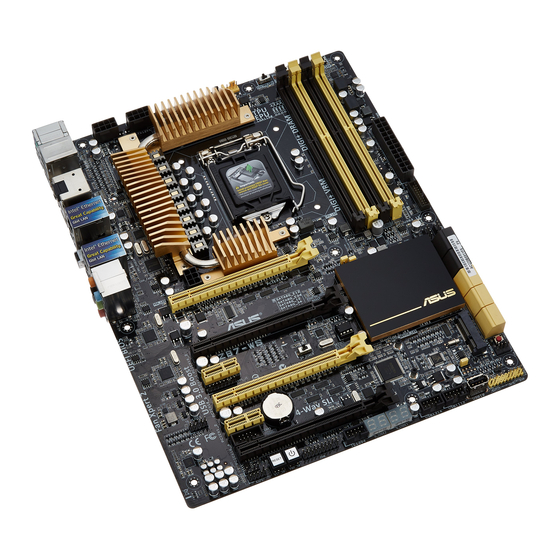
1.2.2 Motherboard layout Parade PS8201 PEX8747 Refer to 1.2.6 Internal connectors and 2.3.1 Rear I/O connection for more information about rear panel connectors and internal connectors. ASUS Z87-WS... -
Page 26: Layout Contents
20. TPM connector (20-1 pin TPM) 1-39 21. Power-on button 1-17 22. Reset button 1-22 23. Front panel audio connector (10-1 pin AAFP) 1-36 24. Digital audio connector (4-1 pin SPDIF_OUT) 1-32 25. ASUS Dr. POWER switch 1-17 Chapter 1: Product introduction 1-10... -
Page 27: Central Processing Unit (Cpu)
Contact your retailer immediately if the PnP cap is missing, or if you see any damage to the PnP cap/socket contacts/motherboard components. ASUS will shoulder the cost of repair only if the damage is shipment/ transit-related. -
Page 28: System Memory
1.2.4 System memory The motherboard comes with four Double Data Rate 3 (DDR3) Dual Inline Memory Modules (DIMM) slots. A DDR3 module is notched differently from a DDR or DDR2 module. DO NOT install a DDR or DDR2 memory module to the DDR3 slot. Recommended memory configurations Chapter 1: Product introduction 1-12... -
Page 29: Memory Configurations
Always install DIMMS with the same CAS Latency. For optimum compatibility, we recommend that you install memory modules of the same version or data code (D/C) from the same vendor. Check with the vendor to get the correct memory modules. ASUS Z87-WS 1-13... - Page 30 Z87-WS Motherboard Qualified Vendors List (QVL) Visit the ASUS website for the latest QVL. Chapter 1: Product introduction 1-14...
-
Page 31: Expansion Slots
PCIe 3.0/2.0 x16_3 slot (single at x16 or dual at x8/x8 mode) PCIe 2.0 x1_2 slot PCIe 3.0/2.0 x16_4 slot (at x8 mode) PCIE x16_1 auto switches to x8 when slot PCIE x16_2 is occupied; PCIE x16_2 auto switches to x4 when slot PCIE x16_4 is occupied. ASUS Z87-WS 1-15... - Page 32 PCIe Express 3.0 operating mode Slot 3-WAY SLI 4-WAY SLI Single VGA CrossFireX CrossFireX CrossFireX (single VGA recommended) — — — (dual VGA recommended) — — — • We recommend that you provide sufficient power when running CrossFireX™ or SLI™ mode.
-
Page 33: Onboard Buttons And Switches
ASUS Dr. POWER switch This switch allows you to enable or disable the ASUS Dr. Power feature. Install the bundled ASUS Dr. Power Utility then enable this switch to allow the system to display notification messages in your Windows screen if a problem is detected with your Power Supply Unit (PSU). - Page 34 BIOS has been restored to its default settings. • We recommend that you download and update to the latest BIOS version from the ASUS website at www.asus.com after using the MemOK! function. Chapter 1: Product introduction 1-18...
- Page 35 Turn off your system using the power-on button to allow your system to go through POST (without entering the BIOS) when you reboot your system. Refer to section 3.8 Boot Menu for details about setting the DirectKey default • function. ASUS Z87-WS 1-19...
- Page 36 TPU switch With its two-level adjustment functions, the TPU allows you to automatically adjust the CPU ratio and clock speed for optimal system performance. • Enable this switch when the system is powered off. • When the TPU switch is set to Enabled (TPU_I: CPU Ratio Boost), the system automatically adjusts the CPU ratio for enhanced performance.
- Page 37 EPU function at the same time. However, the system will use the last setting you have made. Clear CMOS button Press the Clear CMOS switch to clear BIOS setup information only when the system hangs due to overclocking. ASUS Z87-WS 1-21...
- Page 38 Reset button Press the reset button to reboot the system. MSATA switch The mSATA switch configures mSATA support for the motherboard. Auto-detect Force mSATA or mSATA SATA port 6 function Chapter 1: Product introduction 1-22...
-
Page 39: Onboard Leds
(Power-On-Self Test): CPU, memory modules, VGA card, and hard disk drives If an error is found, the critical component’s LED stays lit until the problem is solved. TPU LED The TPU LED lights up when the TPU switch is enabled. ASUS Z87-WS 1-23... - Page 40 EPU LED The EPU LED lights up when the EPU switch is enabled. Q-Code LED The Q-Code LED provides you with a 2-digit error code that displays the system status. Refer to the Q-Code table on the next page for details. Chapter 1: Product introduction 1-24...
- Page 41 Unspecified memory initialization error Memory not installed Invalid CPU type or Speed CPU mismatch CPU self test failed or possible CPU cache error CPU micro-code is not found or micro-code update is failed (continued on the next page) ASUS Z87-WS 1-25...
- Page 42 Code Description Internal CPU error Reset PPI is not available 5C – 5F Reserved for future AMI error codes S3 Resume is stared (S3 Resume PPI is called by the DXE IPL) S3 Boot Script execution Video repost OS S3 wake vector call E4 –...
- Page 43 USB Enable 9E – 9F Reserved for future AMI codes IDE initialization is started IDE Reset IDE Detect IDE Enable SCSI initialization is started SCSI Reset SCSI Detect SCSI Enable Setup Verifying Password (continued on the next page) ASUS Z87-WS 1-27...
- Page 44 Code Description Start of Setup Reserved for ASL (see ASL Status Codes section below) Setup Input Wait Reserved for ASL (see ASL Status Codes section below) Ready To Boot event Legacy Boot event Exit Boot Services event Runtime Set Virtual Address MAP Begin Runtime Set Virtual Address MAP End Legacy Option ROM Initialization System Reset...
- Page 45 System has transitioned into ACPI mode. Interrupt controller is in APIC mode. PWR_SUPPLY LED The ASUS Dr. Power LED near the EATX PWR connector lights up when the ASUS Dr. Power switch setting is on Enable and the power supply unit has failed.
- Page 46 PGLED3 LED The ASUS Dr. Power LED near the ASUS Dr. Power switch lights up when the ASUS Dr. Power switch is on Enable. +12V_PWR LED The ASUS Dr. Power LED near EATX12V connector lights up when the ASUS Dr.
-
Page 47: Internal Connectors
ATA RAID set using these connectors, set the SATA Mode item in the BIOS to [RAID Mode]. Refer to section 3.6.3 SATA Configuration for details. Before creating a RAID set, refer to section 5.1 RAID configurations or the manual • bundled in the motherboard support DVD. ASUS Z87-WS 1-31... - Page 48 Marvell 9230 ATA 6.0 Gb/s connectors (7-pin SATA6G_E1234 [dark brown]) These connectors connect to Serial ATA 6.0 Gb/s hard disk drives via Serial ATA 6.0 Gb/s signal cables. Z87-WS Marvell SATA 6.0 Gb/s connectors • Marvell storage controller can only support AHCI mode.
- Page 49 IEEE 1394 port connector (10-1 pin IE1394) This connector is for an IEEE 1394 port. Connect the IEEE 1394 module cable to this connector, then install the module to a slot opening at the back of the system chassis. ASUS Z87-WS 1-33...
- Page 50 DO NOT connect a 1394 cable to the USB connectors. Doing so will damage the motherboard! You can connect the front panel USB cable to the ASUS Q-Connector (USB, dark brown) first, and then install the Q-Connector (USB) to the USB connector onboard if your chassis supports front panel USB ports.
- Page 51 Ensure that the CPU fan is securely installed to the CPU fan connector. • The CPU_FAN connector supports the CPU fan of maximum 1A (12 W) fan power. • The CPU_FAN connector and CHA_FAN connectors support the ASUS FAN Xpert 2 feature. ASUS Z87-WS 1-35...
- Page 52 Front panel audio connector (10-1 pin AAFP) This connector is for a chassis-mounted front panel audio I/O module that supports either HD Audio or legacy AC`97 audio standard. Connect one end of the front panel audio I/O module cable to this connector. •...
- Page 53 We recommend you connect an EATX 12V_1 cable to increase power efficiency when you plug in high-end PCI Express x16 cards. • If you are uncertain about the minimum power supply requirement for your system, refer to the Recommended Power Supply Wattage Calculator at http://support.asus.com/PowerSupplyCalculator/PSCalculator.aspx?SLanguage=en- ASUS Z87-WS 1-37...
-
Page 54: System Panel Connector
System panel connector (20-8 pin PANEL) This connector supports several chassis-mounted functions. • System power LED (2-pin PLED) This 2-pin connector is for the system power LED. Connect the chassis power LED cable to this connector. The system power LED lights up when you turn on the system power, and blinks when the system is in sleep mode. - Page 55 Connect the button cable that supports DirectKey, from the chassis to this connector on the motherboard. Ensure that your chassis comes with the extra button cable that supports the DirectKey feature. Refer to the technical documentation that came with the chassis for details. ASUS Z87-WS 1-39...
- Page 56 mSATA connector This connector is for a single SATA 6.0Gb/s Solid-State Drive (SSD). Connect the SSD to the mSATA port. Chassis intrusion connector (4-1 pin CHASSIS) This connector is for a chassis-mounted intrusion detection sensor or switch. Connect one end of the chassis intrusion sensor or switch cable to this connector. The chassis intrusion sensor or switch sends a high-level signal to this connector when a chassis component is removed or replaced.
-
Page 57: Chapter 2: Basic Installation
The diagrams in this section are for reference only. The motherboard layout may vary with models, but the installation steps are the same for all models. Install the ASUS I/O Shield to the chassis rear I/O panel. Place the motherboard into the chassis, ensuring that its rear I/O ports are aligned to the chassis’... - Page 58 Place nine screws into the holes indicated by circles to secure the motherboard to the chassis. DO NOT overtighten the screws! Doing so can damage the motherboard. Chapter 2: Basic installation...
-
Page 59: Cpu Installation
2.1.2 CPU installation Ensure that you install the correct CPU designed for LGA1150 socket only. DO NOT install a CPU designed for LGA155 and LGA1156 socket on the LGA1150 socket. ASUS Z87-WS... -
Page 60: Cpu Heatsink And Fan Assembly Installation
2.1.3 CPU heatsink and fan assembly installation Apply the Thermal Interface Material to the CPU heatsink and CPU before you install the heatsink and fan, if necessary. To install the CPU heatsink and fan assembly Chapter 2: Basic installation... - Page 61 To uninstall the CPU heatsink and fan assembly ASUS Z87-WS...
-
Page 62: Dimm Installation
2.1.4 DIMM installation To remove a DIMM Chapter 2: Basic installation... -
Page 63: Atx Power Connection
2.1.5 ATX Power connection ASUS Z87-WS... -
Page 64: Sata Device Connection
2.1.6 SATA device connection Chapter 2: Basic installation... -
Page 65: Front I/O Connectors
2.1.7 Front I/O Connectors To install ASUS Q-Connector To install USB 2.0 connector To install front panel audio connector AAFP USB 2.0 To install USB 3.0 connector USB 3.0 ASUS Z87-WS... -
Page 66: Expansion Card Installation
2.1.8 Expansion Card installation To install PCIe x16 cards To install PCIe x1 cards Chapter 2: Basic installation 2-10... -
Page 67: Bios Update Utility
Press the BIOS Flashback button for three seconds until a flashing light appears, which indicates that the BIOS Flashback function is enabled. Wait until the light goes out, indicating that the BIOS updating process is completed. ASUS Z87-WS 2-11... - Page 68 • Updating the BIOS poses some risks. If the BIOS program is damaged during the updating process and the system fails to reboot, please contact your local ASUS Service Center for assistance Chapter 2: Basic installation...
-
Page 69: Motherboard Rear And Audio Connections
Rear panel connectors PS/2 keyboard/mouse combo port Mini-Display Port ASmedia USB 3.0 ports, support Display Port ® ASUS USB 3.0 Boost. Optical S/PDIF Out port HDMI port Intel LAN (RJ-45) port* BIOS Flashback button ® USB 2.0 ports 5 and 6 USB 2.0 ports 3 and 4... - Page 70 • A plugged USB 3.0 device may run on xHCI or EHCI mode, depending on the operating system’s setting. • DO NOT insert a different connector to the external SATA port. • We strongly recommend that you connect USB 3.0 devices to USB 3.0 ports for a faster and better performance from your USB 3.0 devices.
-
Page 71: Audio I/O Connections
– Center/Subwoofer Center/Subwoofer Black – Rear Speaker Out Rear Speaker Out Rear Speaker Out Gray – – – Side Speaker Out 2.3.2 Audio I/O connections Audio I/O ports Connect to Headphone and Mic Connect to Stereo Speakers ASUS Z87-WS 2-15... - Page 72 Connect to 2.1 channel Speakers Connect to 4.1 channel Speakers Connect to 5.1 channel Speakers Chapter 2: Basic installation 2-16...
-
Page 73: Starting Up For The First Time
If you do not see anything within 30 seconds from the time you turned on the power, the system may have failed a power-on test. Check the jumper settings and connections or call your retailer for assistance. ASUS Z87-WS 2-17... -
Page 74: Turning Off The Computer
BIOS Beep Description One short beep VGA detected Quick boot set to disabled No keyboard detected One continuous beep followed by two No memory detected short beeps then a pause (repeated) One continuous beep followed by three No VGA detected short beeps One continuous beep followed by four Hardware component failure... -
Page 75: Chapter 3: Bios Setup
BIOS setup Knowing BIOS The new ASUS UEFI BIOS is a Unified Extensible Interface that complies with UEFI architecture, offering a user-friendly interface that goes beyond the traditional keyboard- only BIOS controls to enable a more flexible and convenient mouse input. You can easily navigate the new UEFI BIOS with the same smoothness as your operating system. -
Page 76: Bios Setup Program
BIOS setup program Use the BIOS Setup to update the BIOS or configure its parameters. The BIOS screen includes navigation keys and brief onscreen help to guide you in using the BIOS Setup program. Entering BIOS at startup To enter BIOS Setup at startup: •... -
Page 77: Ez Mode
• The boot device options vary depending on the devices you installed to the system. • The Boot Menu(F8) button is available only when the boot device is installed to the system. ASUS Z87-WS... -
Page 78: Advanced Mode
3.2.2 Advanced Mode The Advanced Mode provides advanced options for experienced end-users to configure the BIOS settings. The figure below shows an example of the Advanced Mode. Refer to the following sections for the detailed configurations. To access the Advanced Mode, click Exit, then select Advanced Mode or press F7 hotkey. Menu bar General help Back button... -
Page 79: Menu Items
This button allows you to enter notes of the activities that you have done in BIOS. • The Quick Note function does not support the following keyboard functions: delete, cut, copy and paste. • You can only use the alphanumeric characters to enter your notes. ASUS Z87-WS... -
Page 80: My Favorites
Last Modified button This button shows the items that you last modified and saved in BIOS Setup. My Favorites MyFavorites is your personal space where you can easily save and access your favorite BIOS items. Adding items to My Favorites To add frequently-used BIOS items to My Favorites: Use the arrow keys to select an item that you want to add. -
Page 81: Main Menu
RTC RAM via the Clear CMOS button. The Administrator or User Password items on top of the screen show the default [Not • Installed]. After you set a password, these items show [Installed]. ASUS Z87-WS... -
Page 82: Administrator Password
Administrator Password If you have set an administrator password, we recommend that you enter the administrator password for accessing the system. Otherwise, you might be able to see or change only selected fields in the BIOS setup program. To set an administrator password: Select the Administrator Password item and press <Enter>. -
Page 83: Ai Tweaker Menu
Be cautious when changing the settings of the Ai Tweaker menu items. Incorrect field values can cause the system to malfunction. The configuration options for this section vary depending on the CPU and DIMM model you installed on the motherboard. Scroll down to display other BIOS items. ASUS Z87-WS... - Page 84 The following item appears only when you set the Ai Overclocking Tuner to [X.M.P.]. eXtreme Memory Profile Allows you to select the X.M.P. mode supported by your memory module. Configuration options: [Profile #1] [Profile #2] ASUS MultiCore Enhancement [Enabled] Default set to [Enabled] for maximum performance under XMP/Manual/ [Enabled] User-defined memory frequency mode.
- Page 85 Allows you to automatically optimize the CPU Graphics Ratio depending on the system loading. [Manual] Allows you to set a value for an optimal CPU Grapics Ratio. Use the <+> or <-> keys to adjust the CPU graphics ratio. The minimum value depends on the installed CPU. ASUS Z87-WS 3-11...
-
Page 86: Dram Timing Control
OC Tuner [As Is] OC Tuner automatically overclocks the frequency and voltage of CPU and DRAM for enhancing the system performance and accelerates the iGPU performance to the extreme according to the integrated graphics loading. Configuration options: [As Is] [Ratio First] [BCLK First] EPU Power Saving Mode [Disabled] Allows you to enable or disable the EPU power saving function. - Page 87 DRAM IO-L (CHA_R0D1) [Auto] Configuration options: [Auto] [1] - [15] DRAM IO-L (CHA_R1D0 [Auto] Configuration options: [Auto] [1] - [15] DRAM IO-L (CHA_R1D1 [Auto] Configuration options: [Auto] [1] - [15] DRAM IO-L (CHB_R0D0 [Auto] Configuration options: [Auto] [1] - [15] ASUS Z87-WS 3-13...
- Page 88 DRAM IO-L (CHB_R0D1) [Auto] Configuration options: [Auto] [1] - [15] DRAM IO-L (CHB_R1D0 [Auto] Configuration options: [Auto] [1] - [15] DRAM IO-L (CHB_R1D1 [Auto] Configuration options: [Auto] [1] - [15] Third Timings tRDRD [Auto] Configuration options: [Auto] [1] – [7] tRDRD_dr [Auto] Configuration options: [Auto] [1] –...
- Page 89 Configuration options: [Enable Both DIMMS] [Disable DIMM0] [Disable DIMM1] [Disable Both DIMMS] Scrambler Setting [Optimized ...] Allows you to set the optimized scrambler setting for stability. Configuration options: [Optimized (ASUS] [Default (MRC)] DIGI+ Power Control CPU Load-Line Calibration [Auto] Load-line is defined by Intel VRM specification and affects CPU power voltage.
- Page 90 The following items appear only when you set the CPU Voltage Frequency to [Auto]. VRM Spread Spectrum [Disabled] Enable the VRM Spread Spectrum to enhance system stability. Configuration options: [Disabled] [Enabled] Active Frequency Mode [Disabled] Enable the Active Frequency Mode for an enhanced power saving condition.
-
Page 91: Cpu Power Management
DRAM Power Phase Control [Auto] [Auto] Allows you to set the Auto mode. [Optimized] Allows you to set the ASUS optimized phase tuning profile. [Extreme] Allows you to set the full phase mode. CPU Power Management The subitems in this menu allow you to set the CPU ratio and their features. - Page 92 Turbo Mode Parameters Long Duration Package Power Limit [Auto] Allows you to limit the Turbo Ratio’s time duration that exceeds the TDP (Thermal Design Power) for maximum performance. Use the <+> or <-> keys to adjust the value. The values range from 1W t0 4096W. Package Power Time Window [Auto] Also known as Power Limit 1, and allows you to maintain the time window for Turbo Ratio over TDP (Thermal Design Power).
- Page 93 Power Saving Level 3 Threshold [Auto] Lower value provides sufficient overclocking tolerance to enlarge the overclocking potential. Higher value provides better power-saving condition.Use <+> or <-> key to adjust the value. The values range from 0A to 30A at 1Amp increment. ASUS Z87-WS 3-19...
- Page 94 Extreme OV [Disabled] Default set to DIsabled and help to protect CPU not been burned by Over Voltage. When set to Enabled, you might choose high level voltage to overclock, but not guaranteed CPU life. Configuration options: [Disabled] [Enabled] CPU Core Voltage [Auto] Allows you to configure the amount of voltage fed to the cores of the processor.
- Page 95 PCIe controller and power control unit. Increase the amount of voltage when increasing DRAM frequency. Use the <+> or <-> keys to adjust the value. The values range from 0.001V to 0.999V with a 0.001V interval. ASUS Z87-WS 3-21...
- Page 96 CPU Analog I/O Voltage Offset Mode Sign [+] To offset the voltage by a positive value. [–] To offset the voltage by a negative value. CPU Analog I/O Voltage Offset [Auto] Allows you to configure the amount of voltage fed to the analog portion of the I/O on the processor.
- Page 97 BCLK DN is equal to the falling edge of the BCLK DP. You can use the <+> or <-> keys to adjust the value. The values range from 0.1V to 1.9V with a 0.10625V interval. CPU Spread Spectrum [Auto] [Auto] Automatic configuration. [Disabled] Enhances the BCLK overclocking ability. [Enabled] Sets to [Enabled] for EMI control. ASUS Z87-WS 3-23...
-
Page 98: Advanced Menu
Advanced menu The Advanced menu items allow you to change the settings for the CPU and other system devices. Be cautious when changing the settings of the Advanced menu items. Incorrect field values can cause the system to malfunction. Chapter 3: BIOS setup 3-24... -
Page 99: Cpu Configuration
This Item apears only if you installed a CPU that supports the Intel Hyper-threading technology. Active Processor Cores [All] Allows you to choose the number of CPU cores to activate in each processor package. Configuration options: [All] [1] [2] [3] ASUS Z87-WS 3-25... - Page 100 Limit CPUID Maximum [Disabled] [Enabled] Allows legacy operating systems to boot even without support for CPUs with extended CPUID functions. [Disabled] Disables this function. Execute Disable Bit [Enabled] [Enabled] Enables the No-Execution Page Protection Technology. [Disabled] Forces the XD feature flag to always return to zero (0). Intel Virtualization Technology [Disabled] [Enabled] Allows a hardware platform to run multiple operating systems separately...
- Page 101 Allows you to set the duration of C7 latency for C7 state. Configuration options: [Short] [Long] Package C State Support [Auto] Allows you to set the a C-state according to the following configuration options: [Auto] [Enabled] [C0/C1] [C2] [C3] [C6] [CPU C7] [CPU C7s] ASUS Z87-WS 3-27...
-
Page 102: Pch Configuration
3.6.2 PCH Configuration PCI Express Configuration Allows you to configure the PCI Express slots. DMI Link ASPM Control [Auto] Allows you to control the ASPM (Active State Power Management) on both Northbridge side and Southbridge side of the DMI Link. Configuration options: [Disabled] [Enabled] [Auto] ASPM Support [Disabled] Allows you to set the ASPM level. -
Page 103: Sata Configuration
While entering Setup, the BIOS automatically detects the presence of SATA devices. The SATA Port items show Not Present if no SATA device is installed to the corresponding SATA port. Scroll down to display the other BIOS items. ASUS Z87-WS 3-29... - Page 104 SATA Mode Selection [AHCI] Allows you to set the SATA configuration. [Disabled] Disables the SATA function. [IDE] Set to [IDE Mode] when you want to use the Serial ATA hard disk drives as Parallel ATA physical storage devices. [AHCI] Set to [AHCI Mode] when you want the SATA hard disk drives to use the AHCI (Advanced Host Controller Interface).
-
Page 105: System Agent Configuration
Configuration options: [Auto] [32M] [64M] [96M] [128M] [160M] [192M] [224M] [256M] [288M] [320M] [352M] [384M] [416M] [448M] [480M] [512M] [1024M] Render Standby [Auto] Allows you to enable the Intel Graphics Render Standby support to reduce the iGPU power use when idle. Configuration options: [Auto] [Disabled] [Enabled] ASUS Z87-WS 3-31... -
Page 106: Dmi Configuration
iGPU Multi-Monitor [Disabled] Allows you to enable the iGPU Multi-Monitor. The iGPU shared system memory size will be fixed at 64MB. Configuration options: [Disabled] [Enabled] DMI Configuration Allows you to control various DMI (Desktop Management Interface) functions. DMI Gen 2 [Auto] Allows you to enable or disable DMI Gen 2. -
Page 107: Usb Configuration
Enables the operation of xHCI controller. [Enabled] Enables the xHCI controller. [Disabled] Disables the xHCI controller. EHCI Hand-off [Disabled] [Enabled] Enables the support for operating systems without an EHCI hand-off feature. [Disabled] Disables the EHCI Hand-off support. ASUS Z87-WS 3-33... -
Page 108: Platform Misc Configuration
Mass Storage Devices [Auto] Allows the system to detect the devices according to their media formats. Configuration options: [Auto] [Floppy] [Forced FDD] [Hard Disk] [CD-ROM] USB Single Port Control Allows you to enable or disable the individual USB port. Refer to section 1.2.2 Motherboard layout for the location of the USB ports. 3.6.6 Platform Misc Configuration The items in this menu allow you to configure the platform-related features. -
Page 109: Onboard Devices Configuration
Sets the front panel audio connector (AAFP) mode to high definition audio. [AC97] Sets the front panel audio connector (AAFP) mode to legacy AC’97 SPDIF Out Type [SPDIF] [SPDIF] Sets to an SPDIF audio output. [HDMI] Sets to an HDMI audio output. ASUS Z87-WS 3-35... - Page 110 VIA 1394 Controller [Enabled] [Enabled] Enables the VIA 1394 controller. [Disabled] Disables the VIA 1394 controller. Marvell Storage Controller [Enabled] [Enabled] Enables the Marvell Storage controller. [Disabled] Disables the Marvell Storage controller. Marvell Storage OPROM [Disabled] [Enabled] Enables the Marvell Storage OPROM controller. [Disabled] Disables the Marvell Storage OPROM controller.
-
Page 111: Apm
Enables Wake-On-Ring to generate a wake event. Power On By RTC [Disabled] [Disabled] Disables RTC to generate a wake event. When set to [Enabled], the items RTC Alarm Date (Days) and Hour/ [Enabled] Minute/Second will become user-configurable with set values. ASUS Z87-WS 3-37... -
Page 112: Network Stack
3.6.9 Network Stack Network Stack [Disable] This item allows user to disable or enable the UEFI network stack. Configuration options: [Disable] [Enable] The following item appears only when you set the Network Stack to [Enabled]. Ipv4/Ipv6 PXE Support [Enabled] Allows you to enable or disable the Ipv4/Ipv6 PXE boot option. Configuration options: [Disabled] [Enabled] Chapter 3: BIOS setup 3-38... -
Page 113: Monitor Menu
N/A. Select [Ignore] if you do not wish to display the detected speed. CPU core 0-3 Voltage, 3.3V Voltage, 5V Voltage, 12V Voltage The onboard hardware monitor automatically detects the voltage output through the onboard voltage regulators. Select [Ignore] if you do not want to detect this item. ASUS Z87-WS 3-39... - Page 114 CPU Q-Fan Control [Auto] Allows you to set the CPU Q-Fan operating mode. [Advance Mode] Enables the CPU Q-Fan control feature in Advance mode for 4-pin CPU fan. [Auto] Detects the type of CPU fan installed and automatically switches the mode control.
- Page 115 Allows user to select standard or aggressive policy for Dr. Power settings. Configuration options: [Standard] [Aggressive] The Dr. Power Policy BIOS item only appears if the ASUS Dr. Power switch is enabled. Please refer to 1.2.6 Onboard buttons and switches.
-
Page 116: Boot Menu
Boot menu The Boot menu items allow you to change the system boot options. Boot Configuration Fast Boot [Enabled] [Disabled] Allows your system to go back to its normal boot speed. [Enabled] Allows your system to accelerate the boot speed. The following items appear only when you set the Fast Boot to [Enabled]. - Page 117 Disables the DirectKey button. The system will only power on or off when you press the DirectKey button. [Go to BIOS Allows the system to power on and go to the BIOS Setup directly when Setup] you press the DirectKey button. ASUS Z87-WS 3-43...
- Page 118 Boot Logo Display [Auto] [Auto] Automatically adjusts Boot Logo for Windows requirements. ® [Full Screen] Maximizes the boot logo size. [Disabled] Disables the full screen boot logo display during POST. Post Delay Time [3 sec] This item appears only when you set the Full Screen Logo item to [Enabled]. This item allows you to select a desired additional POST waiting time to easily enter the BIOS Setup.
-
Page 119: Secure Boot
® UEFI mode, or other Microsoft Secure Boot non compliant OS. ® Microsoft Secure Boot only supports Windows UEFI mode. ® ® The following item appears only when you set the OS Type to [Windows UEFI mode]. ASUS Z87-WS 3-45... - Page 120 Key Management This item appears only when you set OS Type to [Windows UEFI Mode]. It allows you to manage the Secure Boot keys. Clear Secure Boot keys This item appears only when you load the default Secure Boot keys. This item allows you to clear all default Secure Boot keys.
- Page 121 Append dbx from File Allows you to load the additional dbx from a storage device so that more db’s images cannot be loaded. The dbx file must be formatted as a UEFI variable structure with time-based authenticated variable. ASUS Z87-WS 3-47...
-
Page 122: Tools Menu
3.9.1 ASUS EZ Flash 2 Utility Allows you to run ASUS EZ Flash 2. When you press <Enter>, a confirmation message appears. Use the left/right arrow key to select between [Yes] or [No], then press <Enter> to confirm your choice. -
Page 123: Asus Spd Information
DO NOT shut down or reset the system while updating the BIOS to prevent the system boot failure! • We recommend that you update the BIOS file only coming from the same memory/ CPU configuration and BIOS version. 3.9.3 ASUS SPD Information Allows you to view the DRAM SPD information. ASUS Z87-WS 3-49... -
Page 124: Exit Menu
This option allows you to exit the Setup program without saving your changes. When you select this option or if you press <Esc>, a confirmation window appears. Select Yes to discard changes and exit. ASUS EZ Mode This option allows you to enter the EZ Mode screen. Launch EFI Shell from filesystem device This option allows you to attempt to launch the EFI Shell application (shellx64.efi) from one of... -
Page 125: Updating Bios
Inappropriate BIOS updating may result in the system’s failure to boot. Carefully follow the instructions of this chapter to update your BIOS if necessary. Visit the ASUS website at www.asus.com to download the latest BIOS file for this motherboard. The following utilities allow you to manage and update the motherboard BIOS setup program. -
Page 126: Asus Ez Flash 2
3.11.2 ASUS EZ Flash 2 ASUS EZ Flash 2 allows you to update the BIOS without having to use a bootable floppy disk or an OS-based utility. Before you start using this utility, download the latest BIOS from the ASUS website at www.asus.com. -
Page 127: Asus Crashfree Bios 3
The BIOS file in the motherboard support DVD may be older than the BIOS file published on the ASUS official website. If you want to use the newer BIOS file, download the file at http://support.asus.com and save it to a USB flash drive. -
Page 128: Asus Bios Updater
3.11.4 ASUS BIOS Updater The ASUS BIOS Updater allows you to update the BIOS in DOS environment. This utility also allows you to copy the current BIOS file that you can use as a backup when the BIOS fails or gets corrupted during the updating process. - Page 129 Press <Tab> to switch between screen fields and use the <Up/Down/Home/End> keys to select the BIOS file and press <Enter>. BIOS Updater checks the selected BIOS file and prompts you to confirm BIOS update. Are you sure to update BIOS? ASUS Z87-WS 3-55...
- Page 130 Select Yes and press <Enter>. When BIOS update is done, press <ESC> to exit BIOS Updater. Restart your computer. DO NOT shut down or reset the system while updating the BIOS to prevent system boot failure! • For BIOS Updater version 1.04 or later, the utility automatically exits to the DOS prompt after updating BIOS.
-
Page 131: Chapter 4: Software Support
Support DVD information The contents of the support DVD are subject to change at any time without notice. Visit the ASUS website at www.asus.com for updates. 4.2.1 Running the support DVD Place the support DVD into the optical drive. The DVD automatically displays the Drivers menu if Autorun is enabled in your computer. -
Page 132: Obtaining The Software Manuals
Reader from the Utilities tab before opening the files. Acrobat ® To read about your motherboard’s utility guide: Click Manual tab > ASUS Motherboard Utility Guide. From the Manual folder, open the folder of the software manual that you wish to read. -
Page 133: Software Information
4.3.1 AI Suite 3 AI Suite 3 is an all-in-one interface that integrates several ASUS utilities and allows you to launch and operate these utilities simultaneously. Installing AI Suite 3 To install AI Suite 3 on your computer: Place the support DVD into the optical drive. - Page 134 The screenshots of AI Suite 3 in this user manual are for reference only. The actual screenshots vary with models. • Refer to the software manual in the support DVD or visit the ASUS website at www.asus.com for detailed software configuration. Chapter 4: Software support...
-
Page 135: Dual Intelligent Processors 4
Click to auto-detect the best settings based on actual usage. DO NOT remove your fan during the tuning process. ASUS TPU allows you to manually adjust the CPU frequency, Voltage and GPU Boost, settings to enhance system stability and boost performance. -
Page 136: Cpu Frequency
Using TPU CPU Frequency Click to adjust the Base Clock Frequency, CPU Ratio, and CPU Cache Ratio Click to select the number of cores to adjust Click to save Tick to enable Click to load settings as a Group Tuning a saved profile profile... -
Page 137: Gpu Boost
Click to load a as a profile saved profile • Overclocking results vary with the CPU model and the system configuration. • We recommend that you set up a better thermal environment to prevent overheating from damaging the motherboard. ASUS Z87-WS... -
Page 138: Epu
4.3.3 EPU is an enery management utility that allows you to adjust the CPU, GPU, and Fan Control settings to conserve power. Using EPU Click to configure the Click to configure Click to configure Click to configure settings in Auto mode the settings in High the settings in the settings in Away... - Page 139 You can adjust the CPU wattage from the lowest base to your preferred default value. • Adjusting Max CPU Power may decrease the total power delivery to the CPU and affect the CPU performance under system heavy load. To restore your system to its default settings, reboot your computer. ASUS Z87-WS...
-
Page 140: Digi+ Power Control
4.3.4 DIGI+ Power Control ASUS DIGI+ Power Contol allows you to adjust VRM voltage and frequency modulation to enhance reliability and stability. It also provides the highest power efficiency, generating less heat to extend component lifespan and to minimize power loss. - Page 141 OC range. DRAM Power Phase Control Select Extreme for full phase mode to increase system performance or select Optimized for ASUS optimized phase tuning profile to increase DRAM power efficiency. • The actual performance boost may vary depending on your CPU specification.
-
Page 142: Fan Xpert 2
4.3.5 Fan Xpert 2 Fan Xpert 2 automatically detects and tweaks the fan speeds, and provides you with optimized fan settings based on the fans’ specifications and positions. Click a screen to select the type of fan that you want to customize Click to switch between CPU... - Page 143 Click to apply Click and drag Click to go Click to switch between Click to undo to set the fan’s back to the CPU and chassis fan changes changes previous rotation speed screens screen ASUS Z87-WS 4-13...
- Page 144 RPM Mode RPM Mode allows you to set the fan speed when the CPU temperature is below 75 Click and drag to adjust the fan’s speed Click to go back Click to switch between the to the previous CPU and chassis fan screens screen •...
-
Page 145: Usb 3.0 Boost
Click to select a USB device device for a faster data transfer rate • Visit the ASUS website at www.asus.com for detailed software configuration. • Use USB 3.0 devices for better performance. Data transfer speed varies with USB devices. ASUS Z87-WS... -
Page 146: Network Icontrol
4.3.7 Network iControl Network iControl is a one-stop setup network control center that allows you to manage your network bandwidth and set the bandwidth priority for your running programs. To launch Network iControl, click Network iControl on the AI Suite 3 main menu bar. •... -
Page 147: Info Screen
EZ Profile screen Click to select a network profile Click to save the profile settings or rename the profile Click to add selected application for network priority List of network applications Info screen ASUS Z87-WS 4-17... -
Page 148: Usb Bios Flashback
4.3.8 USB BIOS Flashback USB BIOS Flashback allows you to check and save the latest BIOS version to a USB storage device. Use this utility to quickly check for the latest available BIOS and set a schedule to when you can download for a newer version. To launch USB BIOS Flashback, click USB BIOS Flashback on the AI Suite 3 main menu bar. -
Page 149: Ai Charger
• **Actual charging speeds may vary depending on the charging rate and specifications of your USB device. • To ensure normal charging function, disconnect and reconnect your USB device every time you enable or disable AI Charger+. ASUS Z87-WS 4-19... -
Page 150: Ez Update
4.3.10 EZ Update EZ Update is a utility that allows you to automatically update your motherboard’s software, drivers and the BIOS version easily. With this utlity, you can also manually update the saved BIOS and select a boot logo when the system goes into POST. To launch EZ Update, click EZ Update on the AI Suite 3 main menu bar. -
Page 151: Usb Charger
Click to select the type of USB device that you wish to charge when the system is off Ensure to connect your USB device into the USB port that supports this utility. Refer to your user manual for more details. ASUS Z87-WS 4-21... -
Page 152: System Information
4.3.12 System Information This utility allows you get detailed information of the motherboard, CPU, and memory settings. To launch System Information, click System Information on the AI Suite 3 main menu bar. Viewing the motherboard information From the System Information screen, click MB tab to view the motherboard’s information. Viewing the CPU information From the System Information screen, click CPU tab to view the processor’s information. - Page 153 Viewing the SPD information From the System Information screen, click SPD tab to view the memory’s information. ASUS Z87-WS 4-23...
-
Page 154: Asus Ssd Caching Ii
It combines multiple SSDs and their hard drive capacity to boost the system’s overall performance. Launching ASUS SSD Caching II To launch ASUS SSD Caching, click ASUS SSD Caching II on the AI Suite III main menu bar. Select one or more SSDs... - Page 155 Configuring ASUS SSD Caching II Connect at least one HDD and another SSD to the Marvell SATA ports. ASUS SSD ® Caching automatically detects the HDD and SSDs. Tick one or more SSDs and click the next to the HDD you want to cache your SSD with.
-
Page 156: Audio Configurations
4.3.14 Audio configurations The Realtek audio CODEC provides 8-channel audio capability to deliver the ultimate audio ® experience on your computer. The software provides Jack-Sensing function, S/PDIF Out support, and interrupt capability. The CODEC also includes the Realtek proprietary UAJ ®... -
Page 157: Asus Dr. Power Utility
The utility is used to monitor changes in the power supplied to the system that may affect performance and system stability. ASUS Dr. Power Utility runs on your system only when the Dr. Power switch is enabled. (Please refer to 1.2.6 Onboard buttons and switches for additional details). If the switch is disabled, the Dr. - Page 158 The message will be displayed for 15 seconds or until you click the Close button. ASUS Dr. Power will notify you of the power status if the same conditions are present on your system.
-
Page 159: Chapter 5: Raid Support
With the RAID 10 configuration you get all the benefits of both RAID 0 and RAID 1 configurations. Use four new hard disk drives or use an existing drive and three new drives for this setup. ASUS Z87-WS... -
Page 160: Installing Serial Ata Hard Disks
5.1.2 Installing Serial ATA hard disks This motherboard supports Serial ATA hard disk drives. For optimal performance, install identical drives of the same model and capacity when creating a disk array. To install the SATA hard disks for a RAID configuration: Install the SATA hard disks into the drive bays. -
Page 161: Intel ® Rapid Storage Technology Option Rom Utility
The RAID BIOS setup screens shown in this section are for reference only and may not exactly match the items on your screen. This utility supports a maximum of four hard disk drives for RAID configuration. ASUS Z87-WS... - Page 162 Creating a RAID set To create a RAID set: From the utility main menu, select 1. Create RAID Volume and press <Enter>. The following screen appears: Intel(R) Rapid Storage Technology - Option ROM - v10.5.1.1070 Copyright(C) 2003-10 Intel Corporation. All Rights Reserved. [ CREATE VOLUME MENU ] Name: Volume0...
- Page 163 WARNING: ALL DATA ON SELECTED DISKS WILL BE LOST. Are you sure you want to create this volume? (Y/N): Press <Y> to create the RAID volume and return to the main menu, or <N> to go back to the CREATE VOLUME menu. ASUS Z87-WS...
- Page 164 Deleting a RAID set Be cautious when deleting a RAID set. You will lose all data on the hard disk drives when you delete a RAID set. To delete a RAID set: From the utility main menu, select 2. Delete RAID Volume and press <Enter>. The following screen appears: [ DELETE VOLUME MENU ] Name...
-
Page 165: Creating A Raid Driver Disk
Save changes and exit BIOS. When the Make Disk menu appears, press <1> to create a RAID driver disk. Insert a formatted floppy disk into the USB floppy disk drive, then press <Enter>. Follow the succeeding screen instructions to complete the process. ASUS Z87-WS... -
Page 166: Creating A Raid Driver Disk In Windows
5.2.2 Creating a RAID driver disk in Windows ® To create a RAID driver disk in Windows ® Start Windows ® Plug the USB floppy disk drive and insert a floppy disk. Place the motherboard support DVD into the optical drive. Go to the Intel AHCI/RAID Driver menu then click Intel AHCI/RAID Driver path to open the RAID driver folder. -
Page 167: Chapter 6: Multiple Gpu Support
For Windows XP, go to Control Panel > Add/Remove Programs. For Windows Vista, go to Control Panel > Programs and Features. Select your current graphics card driver/s. For Windows XP, select Add/Remove. For Windows Vista, select Uninstall. Turn off your computer. ASUS Z87-WS... -
Page 168: Installing Two Crossfirex™ Graphics Cards
6.1.3 Installing two CrossFireX™ graphics cards The following pictures are for reference only. The graphics cards and the motherboard layout may vary with models, but the installation steps remain the same. Prepare two CrossFireX-ready graphics cards. Insert the two graphics cards into the PCIEX16 slots. -
Page 169: Installing Three Crossfirex™ Graphics Cards
Ensure that the connectors are firmly in place. Connect three independent auxiliary power sources from the power supply to the three graphics cards separately. Connect a VGA or a DVI cable to the graphics card. ASUS Z87-WS... -
Page 170: Installing Four Crossfirex™ Graphics Cards
6.1.5 Installing four CrossFireX™ graphics cards Prepare four CrossFireX-ready graphics cards. Insert the four graphics cards into the PCIEX16 slots. Refer to Chapter 1 in this user manual for the locations of the PCIEX16 slots recommended for multi-graphics card installation. Ensure that the cards are properly seated on the slots. -
Page 171: Installing The Device Drivers
Launching the AMD Catalyst Control Center To launch the AMD Catalyst Control Center: Right-click on the Windows desktop and select ® Catalyst Control Center. Click Catalyst Control Center to configure the displays and settings of your AMD graphic cards. ASUS Z87-WS... - Page 172 Enabling Dual CrossFireX technology In the Catalyst Control Center window, click Performance > AMD CrossFireX Select Enable CrossFireX Select a GPU combination from the drop-down list. Click Apply to save and activate the GPU settings made. Chapter 6: Multiple GPU technology support...
-
Page 173: Nvidia ® Sli™ Technology
We recommend that you install additional chassis fans for better thermal environment. • The NVIDIA Triple SLI technology is supported by Windows Vista™ operating ® systems and later OS only. • Visit the NVIDIA zone website at http://www.nzone.com for the latest certified graphics cards and supported 3D application list. ASUS Z87-WS... -
Page 174: Installing Two Sli-Ready Graphics Cards
6.2.2 Installing two SLI-ready graphics cards The following pictures are for reference only. The graphics cards and the motherboard layout may vary with models, but the installation steps remain the same. Prepare two SLI-ready graphics cards. Insert the two graphics cards into the PCIEX16 slots. -
Page 175: Installing Three Sli-Ready Graphics Cards
Ensure that the connector is firmly in place. Connect three independent auxiliary power sources from the power supply to the three graphics cards separately. Connect a VGA or a DVI cable to the graphics card. 3-Way SLI bridge ASUS Z87-WS... -
Page 176: Installing Four Sli-Ready Graphics Cards
6.2.4 Installing four SLI-ready graphics cards Prepare four SLI-ready graphics cards. Insert the four graphics cards into the PCIEX16 slots. If your motherboard has more than two PCIEX16 slots, refer to Chapter 1 in this user manual for the locations of the PCIEX16 slots recommended for multi-graphics card installation. -
Page 177: Enabling The Nvidia® Sli™ Technology
NVIDIA Windows ® Control Panel. The NVIDIA Control Panel window appears (See Step B3). If you cannot see the NVIDIA Control Panel item in step (A), select Screen Resolution. From the Screen Resolution window, click Advanced settings. ASUS Z87-WS 6-11... - Page 178 The NVIDIA Control Panel window appears. Enabling SLI settings From the NVIDIA Control Panel window, select Configure SLI, Surround, PhysX. In the Quad-SLI enabled, click Maximize 3D Performance SLI to set the display for viewing SLI rendered content. When done, click Apply.
-
Page 179: Nvidia ® Cuda™ Technology
Insert four Tesla computing processor card(s) into the PCIe x16_1, PCIe x16_3, PCIe x16_5, and PCIe x16_7 slot. Ensure that the cards are properly seated on the slot. ASUS Z87-WS 6-13... - Page 180 Connect either one 8-pin power connector or two 6-pin power connectors from the power supply to the Quadro graphics card and Tesla computing processor card(s). Connect a display cable to the graphics card. SLI bridge Goldfingers Refer to the documentation that came with your graphics card package to install the device drivers.
-
Page 181: Appendices
The use of shielded cables for connection of the monitor to the graphics card is required to assure compliance with FCC regulations. Changes or modifications to this unit not expressly approved by the party responsible for compliance could void the user’s authority to operate this equipment. ASUS Z87-WS... -
Page 182: Canadian Department Of Communications Statement
IC: Canadian Compliance Statement Complies with the Canadian ICES-003 Class B specifications. This device complies with RSS 210 of Industry Canada. This Class B device meets all the requirements of the Canadian interference-causing equipment regulations. This device complies with Industry Canada license exempt RSS standard(s). Operation is subject to the following two conditions: (1) this device may not cause interference, and (2) this device must accept any interference, including interference that may cause undesired operation of the device. -
Page 183: Rf Equipment Notices
ASUS Recycling/Takeback Services ASUS recycling and takeback programs come from our commitment to the highest standards for protecting our environment. We believe in providing solutions for you to be able to responsibly recycle our products, batteries, other components as well as the packaging materials. - Page 184 Bluetooth Industry Canada Statement This Class B device meets all requirements of the Canadian interference-causing equipment regulations. Cet appareil numérique de la Class B respecte toutes les exigences du Règlement sur le matériel brouilleur du Canada. NCC: Taiwan Wireless Statement Japan RF Equipment Statement KC (RF Equipment) Appendices...
-
Page 185: Asus Contact Information
+1-812-282-3777 +1-510-608-4555 Web site usa.asus.com Technical Support Telephone +1-812-282-2787 Support fax +1-812-284-0883 Online support support.asus.com ASUS COMPUTER GmbH (Germany and Austria) Address Harkort Str. 21-23, D-40880 Ratingen, Germany +49-2102-959911 Web site www.asus.de Online contact www.asus.de/sales Technical Support Telephone +49-1805-010923* Support Fax... - Page 186 Appendices...