Table of Contents
Advertisement
Quick Links
Advertisement
Table of Contents

Related Manuals for Integra DTR-50.2


Summary of Contents for Integra DTR-50.2
- Page 1 AV Receiver DTR-50.2 Instruction Manual...
-
Page 2: Introduction
Introduction AVIS WARNING: WARNING RISK OF ELECTRIC SHOCK RISQUE DE CHOC ELECTRIQUE TO REDUCE THE RISK OF FIRE OR ELECTRIC DO NOT OPEN NE PAS OUVRIR SHOCK, DO NOT EXPOSE THIS APPARATUS TO The lightning flash with arrowhead symbol, within an RAIN OR MOISTURE. -
Page 3: Precautions
Precautions 1. Recording Copyright—Unless it’s for personal use For U.S. models only, recording copyrighted material is illegal without FCC Information for User the permission of the copyright holder. CAUTION: 2. AC Fuse—The AC fuse inside the unit is not user-ser- The user changes or modifications not expressly approved viceable. -
Page 4: Supplied Accessories
Supplied Accessories Thank you for purchasing an Integra AV receiver. Please read this manual thoroughly before making con- nections and plugging in the unit. Make sure you have the following accessories: Following the instructions in this manual will enable you... -
Page 5: Table Of Contents
Using the Home Menu..........26 Entering Remote Control Codes........91 Changing the Input Display .......... 27 Remote Control Codes for Using Headphones............27 Integra/Onkyo Components Connected via ..91 Using Activities to Start Easy Macros......27 Resetting Remote Mode Buttons........92 Audyssey MultEQ ®... -
Page 6: Features
Features Amplifier Miscellaneous • 135 Watts/Channel @ 8 ohms (FTC) • 40 SIRIUS /FM/AM Presets (North American mod- els) • 180 Watts/Channel @ 6 ohms (IEC) • 40 FM/AM Presets (Australian models) • 230 Watts/Channel @ 6 ohms (JEITA) • Audyssey MultEQ ®*4 to Correct Room Acoustic Prob- •... - Page 7 SIRIUS, XM and all related marks and logos are trademarks of Sirius XM Radio Inc. and its subsidiaries. All rights reserved. Service not available in Alaska and Hawaii. iPhone, iPod, iPod classic, iPod nano, iPod shuffle, and iPod touch are trademarks of Apple Inc., registered in the U.S. and other countries.
-
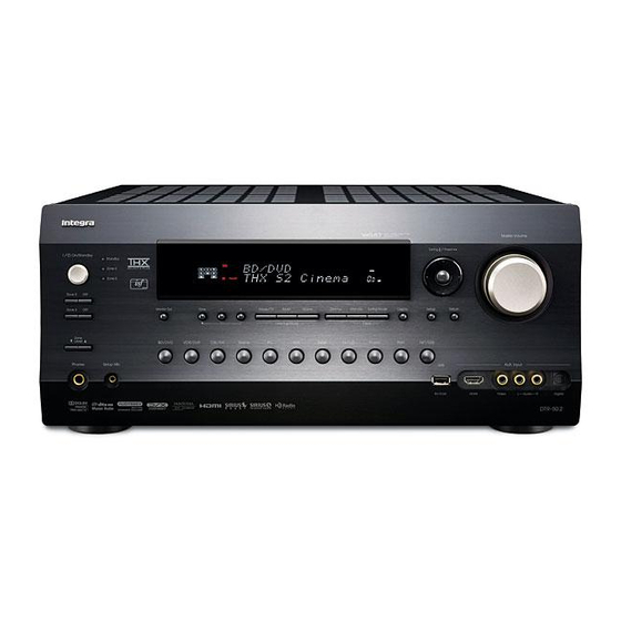
Page 8: Front & Rear Panels
Front & Rear Panels Front Panel North American models Australian models The actual front panel has various logos printed on it. They are not shown here for clarity. The page numbers in parentheses show where you can find the main explanation for each item. On/Standby button (➔... -
Page 9: Display
Display For detailed information, see the pages in parentheses. Speaker/channel indicators Bi AMP indicator (➔ Z2 (Powered Zone 2) indicator (➔ Headphone indicator (➔ Listening mode and format indicators (➔ 41, 65) Audyssey indicator (➔ 28, 53) Dynamic EQ indicator (➔... -
Page 10: Rear Panel
Rear Panel DIGITAL IN COAXIAL and OPTICAL jacks GND screw RS232 terminal SIRIUS antenna jack (North American models) Terminal for control. Composite, S-Video and analog audio jacks REMOTE CONTROL jack (BD/DVD IN, VCR/DVR IN and OUT, CBL/SAT IN, GAME IN, PC IN, TV/CD IN and PHONO IN) ETHERNET port Multichannel input jacks UNIVERSAL PORT jack... -
Page 11: Remote Controller
Remote Controller Controlling the AV Receiver To control the AV receiver, press Receiver to select Receiver mode. You can also use the remote controller to control Onkyo Blu-ray Disc/DVD player, CD player and other components. See “Entering Remote Control Codes” for more 91). -
Page 12: About Home Theater
About Home Theater Enjoying Home Theater Thanks to the AV receiver’s superb capabilities, you can enjoy surround sound with a real sense of movement in your own home—just like being in a movie theater or concert hall. With Blu-ray Discs or DVDs, you can enjoy DTS and Dolby Digital. -
Page 13: Connections
Connections Connecting the AV Receiver Speaker Connection Precautions Connecting Your Speakers Read the following before connecting your speakers: Speaker Configuration • You can connect speakers with an impedance of between 4 and 16 ohms. If the impedance of any of the connected The following table indicates the channels you should use speakers is 4 ohms or more, but less than 6 ohms, be sure depending on the number of speakers that you have. - Page 14 Connecting the Speaker Cables Screw-type speaker terminals Strip 1/2" to 5/8" (12 to 15 mm) of 1/2" to 5/8"(12 to 15 mm) insulation from the ends of the speaker cables, and twist the bare wires tightly, as shown. Using Banana Plugs (North American models) •...
- Page 15 Using Dipole Speakers Normal speakers Dipole speakers You can use dipole speakers for the surround and surround back speakers. Dipole speakers output the same sound in two directions. TV/screen TV/screen Dipole speakers typically have an arrow printed on them to indicate how they should be positioned.
-
Page 16: Connecting A Power Amplifier
Connecting a Power Amplifier If you want to use a more powerful power amplifier and use the AV receiver as a preamp, connect it to the PRE OUT jacks, and connect all speakers and the subwoofer to the power amplifier. If you have a powered subwoofer, connect it to this AV receiver’s SUBWOOFER PRE OUT jack. -
Page 17: About Av Connections
About AV Connections Connected image with AV components HDMI cable Other cables : Video & Audio : Video : Audio AV receiver AV receiver Blu-ray Disc/ Blu-ray Disc/ DVD player DVD player Game console Game console TV, projector, etc. TV, projector, etc. •... -
Page 18: Connecting Your Components With Hdmi
Connecting Your Components with HDMI VCR or DVD recorder/Digital Video Recorder Game console TV, projector, etc. Personal computer Blu-ray Disc/DVD player Camcorder Satellite, cable, set-top box, etc. Connect your components to the appropriate jacks. The default input assignments are shown below. ✔: Assignment can be changed 49, 50). -
Page 19: Connecting Your Components
Connecting Your Components Front Rear Connect your components to the appropriate jacks. The default input assignments are shown below. ✔: Assignment can be changed (➔ 50, 51). Jack Signal Components Assignable AUX Input Video Composite video Camcorder, etc Audio L/R Analog audio Digital Digital audio... -
Page 20: Connecting Integra/Onkyo Components
(➔ 40). Connecting Integra/Onkyo Components Note Step 1: Make sure that each Integra/Onkyo component is con- • Use only cables for connections. cables are supplied with Integra/Onkyo players (DVD, CD, etc.). nected with an analog audio cable (connection... -
Page 21: Connecting Antenna
Connecting Antenna This section explains how to connect the supplied indoor FM antenna and AM loop antenna. The AV receiver won’t pick up any radio signals without any antenna connected, so you must connect the antenna to use the tuner. Caution (North American (Australian models) -
Page 22: Which Connections Should I Use
Which Connections Should I Use? The AV receiver supports several connection formats for compatibility with a wide range of AV equipment. The format you choose will depend on the formats supported by your components. Use the following sections as a guide. Video Connection Formats Video component can be connected by using any one of the following video connection formats: composite video, S-Video, PC IN (Analog RGB), component video or HDMI, the latter offering the best picture quality. - Page 23 ■ “Monitor Out” setting set to “Analog” Video input signals flow through the AV receiver as shown, Video Signal Flow Chart with composite video, S-Video and PC IN (Analog RGB) Blu-ray Disc/DVD player, etc. sources being upconverted for the component video output. Use this setting if you connect the AV receiver’s COMPO- NENT VIDEO MONITOR OUT to your TV.
-
Page 24: Turning On & Basic Operations
Turning On & Basic Operations Turning On/Off the AV Receiver On/Standby Standby indicator Standby Receiver Front panel Remote controller Turning On Press On/Standby on the front panel. Press Receiver followed by On on the remote controller. The AV receiver comes on, the display lights, and the Standby indicator goes off. Pressing the remote controller’s On again will turn on any components connected via Turning Off Press On/Standby on the front panel. -
Page 25: Basic Operations
Basic Operations Displaying Source Information This manual describes the procedure using the remote controller unless otherwise specified. You can display various information about the current input source as follows. (Components connected to the Selecting the Language Used for the UNIVERSAL PORT jack are excluded.) Onscreen Setup Menus Press Receiver followed by Display repeatedly to You can determine the language used for the onscreen... -
Page 26: Muting The Av Receiver
Muting the AV Receiver Using the Home Menu You can temporarily mute the output of the AV receiver. The Home menu provides you quick access to frequently used menus without having to go through the long stan- Press Receiver followed by Muting. dard menu. -
Page 27: Changing The Input Display
Using Headphones Note If Direct listening mode is selected, “Dynamic EQ” and Connect a pair of stereo headphones with a stan- “Dynamic Volume” cannot be selected. dard plug (1/4 inch or 6.3 mm) to the Phones Only when you have selected “Custom” in the “Picture 59), pressing Enter allows you to adjust the fol- Mode”... -
Page 28: Audyssey Multeq ® Room Correction And Speaker Setup
My Music: Audyssey MultEQ ® Room Correction 1. The playback component assigned to TV/CD of and Speaker Setup Remote Mode turns on. With the supplied calibrated microphone, 2. The AV receiver turns on. Audyssey MultEQ automatically determines the number 3. The input selector of the AV receiver is set to of speakers connected, their size for purposes of bass man- TV/CD. - Page 29 If you use a powered subwoofer(s), adjust the sub- woofer volume level to 75dB. Test tones are played through the subwoofer. Use the volume control on the subwoofer. Note • If your subwoofer does not have a volume control, disre- gard the level displayed and press Enter to proceed to the next step.
- Page 30 Changing the Speaker Settings Manually Note • When Audyssey MultEQ ® Room Correction and Speaker Setup You can manually make changes to the settings found dur- 53). is complete, the “Equalizer” will be set to “Audyssey” (➔ ing Audyssey MultEQ Room Correction and Speaker The Audyssey indicator will light (➔...
-
Page 31: Listening To The Radio
Listening to the Radio ■ Manual tuning mode This section describes the procedure using the but- tons on the front panel unless otherwise specified. Press Tuning Mode so that the AUTO indicator goes off on the display. Using the Tuner Press and hold Tuning / . -
Page 32: Presetting Fm/Am Stations
Presetting FM/AM Stations Listening to SIRIUS Satellite Radio ® (North American models) You can store a combination of up to 40 of your favorite FM/AM radio stations as presets. To listen to Satellite Radio, you’ll need to connect a SIR- IUS Satellite Radio tuner (sold separately) to your Sirius- Tune into the FM/AM station that you want to Ready receiver. - Page 33 Setting Up the SiriusConnect™ Home Tuner The optional SiriusConnect Home tuner kit includes Display everything for easy home installation, including the Sirius- Connect receiver, indoor/outdoor antenna with 21-foot cable, 8-pin mini DIN connector cable, and an AC power Tuner adapter. See the SiriusConnect Home tuner’s instructions for more information.
- Page 34 Selecting Channels using the Remote Use / to select “SAT Radio Mode”, and Controller select “SIRIUS”. Pressing cycles through the following options: There are three ways to select SIRIUS Satellite Radio None: channels: Select if you’re not using Satellite Radio. 1.
- Page 35 ■ Selecting the previously selected channel SIRIUS Parental Lock With SIRIUS Parental Lock, you can lock out channels Press Return to select the previously selected that you do not want to receive and use a 4-digit PIN num- channel. ber to prevent others from unlocking them. Selecting Channels on the AV Receiver Press Receiver followed by Setup.
- Page 36 Use / to select “Parental Lock”, and then press to select a number on the screen, and Enter. then press Enter. The channel number, channel name, and the current Repeat this for each of the four digits in the PIN status are displayed.
- Page 37 Displaying SIRIUS Satellite Radio Position the SiriusConnect Home antenna so that Information as many bars as possible (up to 3) appear on the Satellite signal strength meter. Press Display repeatedly to cycle through the available information. Antenna Aiming SIRIUS Satellite Terrestrial The following information can be displayed: Channel name and Channel number...
-
Page 38: Using Rds (Australian Models)
Finding Stations by Type (PTY) Using RDS (Australian models) You can search for radio stations by type. RDS works only in areas where RDS broadcasts are available. Press RT/PTY/TP twice. The current program type appears on the display. When tuned into an RDS station, the RDS indicator lights. Use Preset to select the type of program you want. - Page 39 ■ RDS program types (PTY) Type Display None None News reports News Current affairs Affairs Information Info Sport Sport Education Educate Drama Drama Culture Culture Science and technology Science Varied Varied Pop music Pop M Rock music Rock M Middle of the road music Easy M Light classics Light M...
-
Page 40: Recording
Recording This section explains how to record the selected input source to a component with recording capability, and how to record audio and video from different sources. Connecting a Recording Component Recording Separate AV Sources Here you can record audio and video from completely separate sources, allowing you to overdub audio onto your video recordings. -
Page 41: Using The Listening Modes
Using the Listening Modes Selecting Listening Modes 42). See “About Listening Modes” for detailed information about the listening modes (➔ Listening Mode Buttons Press Receiver first. Movie/TV, Music, Game Music Game Movie/TV Movie/TV button Game button This button selects the listening modes intended for use This button selects the listening modes intended for use with movies and TV. -
Page 42: About Listening Modes
About Listening Modes The AV receiver’s listening modes can transform your listening room into a movie theater or concert hall, with high fidel- ity and stunning surround sound. Explanatory Notes SP Layout Front speakers Center speaker Listening Surround speakers Mode Subwoofer(s) Surround back speakers Front high speakers... -
Page 43: Listening Modes
Listening Modes Listening Mode Description Input Speaker Source Layout Direct In this mode, audio from the input source is output without surround-sound processing. The “Speaker Configuration” (presence of speakers), D i r e c t d i o P P o P P “Sp Distance”... - Page 44 Listening Mode Description Input Speaker Source Layout DTS-HD High (Continued from the previous page.) Resolution Audio D T S – H D H R DTS-HD Master Audio D T S – H D M S T R DTS Express D T S E x p r e s s D S D DTS 96/24...
- Page 45 Listening Mode Description Input Speaker Source Layout Founded by George Lucas, THX develops stringent standards that ensure movies are reproduced in movie theaters and home theaters just as the direc- T H X C i n e m a tor intended. THX Modes carefully optimize the tonal and spatial character- istics of the soundtrack for reproduction in the home-theater environment.
- Page 46 Onkyo-Original DSP Listening Modes Listening Mode Description Input Speaker Source Layout Orchestra Suitable for classical or operatic music, this mode emphasizes the surround channels in order to widen the stereo image, and simulates the natural rever- O r c h e s t r a beration of a large hall.
-
Page 47: Advanced Operations
Advanced Operations Advanced Setup On-screen Setup Menus Common Procedures in Setup Menu This manual describes the procedure using the remote controller unless otherwise specified. Receiver MENU Enter 1. Input/Output Assign / / / 2. Speaker Setup 3. Audio Adjust 4. Source Setup Setup Return 5. -
Page 48: Input/Output Assign
■ Explanatory Notes Monitor Out Analog: Select this if your TV is connected to the COMPO- Main Menu Speaker Setup NENT VIDEO MONITOR OUT, MONITOR OUT ■ Subwoofer S, or MONITOR OUT V. Yes: HDMI Main: Select if a subwoofer is connected. Select this if your TV is connected to the HDMI OUT MAIN. -
Page 49: Hdmi Input
■ Resolution HDMI Input You can specify the output resolution for the HDMI output If you connect a video component to an HDMI input, you and COMPONENT VIDEO MONITOR OUT and have must assign that input to an input selector. For example, if the AV receiver upconvert the picture resolution as neces- you connect your Blu-ray Disc/DVD player to HDMI sary to match the resolution supported by your TV. -
Page 50: Digital Audio Input
■ BD/DVD, VCR/DVR, CBL/SAT, GAME, PC, AUX, Note TV/CD, PHONO, PORT • For composite video, S-Video, and component video upconver- IN 1, IN 2, IN 3: sion for the HDMI output, the “HDMI Input” setting must be Select a corresponding component video input that set to “- - - - -”. -
Page 51: Speaker Setup
■ Analog Audio Input Speakers Type(Front) Normal: Some DVD players output the LFE channel from their Select this if you’ve connected your front speakers analog subwoofer output at 15 dB higher than normal. normally. With this setting, you can change the AV receiver’s sub- Bi-Amp: woofer sensitivity to match your DVD player. -
Page 52: Speaker Distance
■ Front Wide *1*2*4*6 , Front High *1*2*4*5 Speaker Distance Full Band 40Hz, 45Hz, 50Hz, 55Hz, 60Hz, 70Hz, 80Hz(THX) This setting is set automatically by Audyssey MultEQ to 130Hz, 150Hz, 200Hz Room Correction and Speaker Setup function (➔ 28). None: Select if no speaker is connected. - Page 53 Equalizer Settings THX Audio Setup With the “SurrBack Speaker Spacing” setting, you can This setting is set automatically by Audyssey MultEQ ® specify the distance between your surround back speakers. Room Correction and Speaker Setup function (➔ 28). If you’re using a THX-certified subwoofer, set the “THX Ultra2/Select2 Subwoofer”...
-
Page 54: Audio Adjust
■ Preserve THX Settings Input Channel Yes: Left + Right: ® Audyssey Dynamic EQ Both the left and right channels are output. Audyssey Dynamic Volume ® will not be active in Left: THX listening mode. Only the left channel is output. Right: Audyssey Dynamic EQ / Only the right channel is output. -
Page 55: Lfe Level
■ PLIIz Height Gain Theater-Dimensional The Height Gain Control in Dolby Pro Logic IIz ■ enables the listener to select how much gain is applied Listening Angle to the front high speakers. There are three settings, Wide: “Low”, “Mid” and “High”, and the front high speakers Select if the listening angle is 40 degrees. -
Page 56: Source Setup
Audyssey Dynamic EQ is referenced to the standard Source Setup film mix level. It makes adjustments to maintain the ref- erence response and surround envelopment when the Items can be set individually for each input selector. volume is turned down from 0 dB. However, film refer- ence level is not always used in music or other non-film Preparation content. -
Page 57: A/V Sync
IntelliVolume About Audyssey Dynamic EQ ® Audyssey Dynamic EQ solves the problem of deterio- ■ IntelliVolume rating sound quality as volume is decreased by taking –12dB to 0dB to +12dB in 1 dB steps. into account human perception and room acoustics. With IntelliVolume, you can set the input level for each Dynamic EQ selects the correct frequency response and input selector individually. -
Page 58: Picture Adjust
Picture Adjust Name input area Using “Picture Adjust”, you can adjust the picture qual- 4-4. Name Edit BD/DVD ity and reduce any noise appearing on the screen. Name To view the TV picture while setting, press Enter. To return to the previous screen, press Return. –... - Page 59 ■ ■ Picture Mode Noise Reduction *2*4*6 Custom: Off: All settings can be performed manually. Noise reduction off. ISF Day: Low: Setting when a room is bright. Low noise reduction. ISF Night: Mid: Setting when a room is dark. Medium noise reduction. Cinema: High: Selected when the picture source is movie film, etc.
-
Page 60: Listening Mode Preset
■ Gamma *2*4 Listening Mode Preset –3 to 0 to +3 Adjust the balance of incoming picture R (red), G You can assign a default listening mode to each input (green), and B (blue) color data signal to the output source that will be selected automatically when you select color data signal. -
Page 61: Miscellaneous
To disable this setting, select “Off”. 1, 2, or 3 ■ Power On Volume When several Integra/Onkyo components are used in Last, Min, 1 to 99 or Max (Absolute display) the same room, their remote ID codes may overlap. To Last, –... - Page 62 Multi Zone TV’s speakers (➔ 18), if you turn up the AV receiver’s volume control, the sound will be output by the AV receiver’s front left 79). See “Setting the Multi Zone” (➔ and right speakers. To stop the AV receiver’s speakers producing sound, change the settings, change your TV’s settings, or turn Tuner down the AV receiver’s volume.
-
Page 63: Auto Power Down
■ ■ Audio Return Channel TV Control Off: Off: Select “Off” if you don’t want to use audio return TV Control disabled. channel (ARC) function. Auto: TV Control enabled. The audio signal from your TV tuner can be sent to Set to “On”... -
Page 64: Lock Setup
• Perform the firmware update only when an announcement is 26). menu (➔ posted on the Integra web site. See the Integra web site for latest information. Press Receiver followed by Home. • It takes about 30 minutes to complete the firmware update. - Page 65 Audyssey Settings Music Optimizer The Music Optimizer function enhances the sound quality ■ Dynamic EQ of compressed music files. Use it with music files that use See “Dynamic EQ” of “Source Setup” (➔ 56). “lossy” compression, such as MP3. ■ Dynamic Volume ■...
- Page 66 Audio Selector Setting the Incoming Digital Signal (Fixed Mode) You can set priorities of audio output when there are both digital and analog inputs. By pressing Enter while selecting “HDMI”, “COAX”, “OPT” in the “Audio Selector”, you can specify the input ■...
-
Page 67: Net/Usb
NET/USB About NET Connecting the AV Receiver The AV receiver is network-ready, which means you can To connect the AV receiver to your home network, plug hook it up to your home network with a standard Ethernet one end of a shielded CAT5 Ethernet cable into the AV cable and enjoy the music files stored on your computer or receiver’s ETHERNET port, and plug the other end into a media server. -
Page 68: Listening To Internet Radio
Press NET/USB repeatedly to select the Internet Listening to Internet Radio Radio screen. To receive Internet radio, you must connect the AV 67). Internet Radio receiver to a network with Internet access (➔ 1. vTuner Internet Radio You can select Internet radio stations by connecting to the 2. -
Page 69: Playing Music Files On A Server
Listening to Other Internet Radio Playing Music Files on a Server To listen to other internet radio stations, insert the follow- This section explains how to play music files on a com- ing step after step 1 in the “Listening to vTuner Internet puter or media server through the AV receiver. - Page 70 Random Playback Use / to select a server, and then press Enter. The Random function can only be set while the PLAY A list of items on the server appears. screen is displayed. To play songs in random order, during playback (or while Server1 playback is paused or stopped), press Random.
- Page 71 ■ Supported Audio File Formats AAC stands for MPEG-2/MPEG-4 Audio. For server playback, the AV receiver supports the follow- • Sampling rates of 8 kHz, 11.025 kHz, 12 kHz, 16 kHz, ing music file formats: MP3, WMA, WAV, FLAC, Ogg 22.05 kHz, 24 kHz, 32 kHz, 44.1 kHz, 48 kHz, 64 kHz, Vorbis, AAC and LPCM.
-
Page 72: Remote Playback From Media Server/Personal Computer
Server Requirements Remote Playback from Media Server/ Personal Computer The AV receiver can play digital music files stored on a computer or media server and supports the following tech- Remote Playback means you can play the music files nologies: stored on the DLNA-certified device such as media server •... -
Page 73: Network Settings
Using Remote Playback Adjusting the Volume. You can adjust the volume of your AV receiver by adjusting the volume bar in the “Remote Playback” Start Windows Media ® Player 12. window. The default maximum volume for the AV Before remote playback, setup on Windows Media receiver is 82 (0dB). - Page 74 ■ Press Receiver, followed by Setup. DHCP The main menu appears onscreen. This setting determines whether or not the AV receiver uses DHCP to automatically configure its IP Address, If the main menu doesn’t appear, make sure the Subnet Mask, Gateway, and DNS Server settings. appropriate external input is selected on your TV.
-
Page 75: About Usb
Plug your USB mass storage device into the AV About USB receiver’s USB port. USB can be used to play music files stored on USB mass Press NET/USB repeatedly to select the “USB” storage devices (e.g., USB flash drives and MP3 players), input. - Page 76 Random Playback The Random function can only be set while the PLAY screen is displayed. To play songs in random order, while the list of songs is displayed, press Random. All of the songs in the current folder will be played in random order. When all of the songs in the folder have been played once, they’ll all be played again in a different random order.
-
Page 77: Multi Zone
Multi Zone In addition to your main listening room, you can also enjoy playback in the other room, or as we call Multi Zone. And, you can select a different source for each room. Connecting Your Zone 2 Speakers to an Connecting Zone 2 Amp in Zone 2 There are two ways you can connect Zone 2 speakers:... -
Page 78: Connecting Zone 3
Zone 2 Video Output Connecting Zone 3 The AV receiver features a composite video output for con- Connecting Your Zone 3 Speakers to an nection to a TV in Zone 2, so you can enjoy both audio and Amp in Zone 3 video in that zone. -
Page 79: Setting The Powered Zone 2
Setting the Powered Zone 2 Setting the Multi Zone If you’ve connected your Zone 2 speakers to the AV Press Receiver followed by Setup. receiver, as explained in “Connecting Your Zone 2 Speak- The main menu appears onscreen. ers Directly to the AV receiver” (➔... -
Page 80: Using Zone 2/3
■ Zone 2 Power On Volume, Using Zone 2/3 Zone 3 Power On Volume Last, Min, 1 to 99 or Max (Absolute display) This section explains how to turn Zone 2/3 on and off, how to select an input source for Zone 2/3, and how to Last, –... - Page 81 Controlling Zone 2/3 with the Remote Adjusting the Volume for Zones Controller On the remote controller, press Zone repeatedly, Standby and then use VOL / . Zone On the AV receiver, press Zone 2 or Zone 3, and then press Zone Level Down and Up .
-
Page 82: Using The 12V Triggers
Using the 12V Triggers Use / to select “Delay”, and use to select: 0sec (Trigger A: default), The 12V triggers A, B, and C can be used to turn on 12V 1sec (Trigger B: default), trigger-capable components automatically when they are 2sec (Trigger C: default), selected as the input source. -
Page 83: Using The Remote Controller In Zone 2/3 And Multiroom Control Kits
Using a Multiroom Kit with a Cabinet Using the Remote Controller in Zone 2/3 and Multiroom Control Kits In this setup, the IR receiver picks up the infrared signals from the remote controller and feeds them to the AV To control the AV receiver with the remote controller receiver located in the cabinet via the connecting block. -
Page 84: Controlling Ipod & Other Components
Controlling iPod & Other Components Controlling iPod Press NET/USB repeatedly to select the USB Connecting the iPod Directly to the input. USB Port Connect the USB cable that comes with the iPod/ USB can be used to play music files stored on iPod/iPhone, iPhone to the USB port at the front of the AV which can be plugged into the AV receiver’s USB port. -
Page 85: Connecting An Onkyo Dock
Extended Mode control • Genres • Songs The content information is displayed (lists are displayed) • Composers on the on-screen, and you can select and manipulate the • Shuffle Songs content while looking at the screen. • Now Playing Top screen list: Displays a list. -
Page 86: Using The Onkyo Dock
■ Using Your iPod models Alarm Clock Using the Onkyo Dock You can use your iPod models Alarm Clock function to automatically turn on your iPod and the AV receiver at a Dock is sold separately. specified time. The AV receiver’s input source will auto- For the latest information on the Onkyo Dock compo- matically be set to the Port selector. -
Page 87: Controlling Your Ipod
■ System Function Controlling Your iPod System On When you turn on the AV receiver, RI Dock and iPod turn By pressing Remote Mode that’s been programmed with on automatically. In addition, when the RI Dock and iPod the remote control code for your Dock, you can control are on, the AV receiver can be turned on by pressing On/ your iPod in the Dock. - Page 88 ✔: Available buttons Press the appropriate Remote Mode first. Onkyo Dock Buttons ✔ On, Standby ✔ Top Menu ✔ ✔ / / / Enter ✔ ✔ Playlist ✔ ✔ ✔ ✔ Repeat ✔ ✔ Random ✔ ✔ Play Mode ✔ ✔...
-
Page 89: Controlling Other Components
For details on controlling these components, see the pages indicated. Use / / / to select a character, and then press Enter. BD/DVD Integra/Onkyo Blu-ray Disc player (➔ Repeat this step from the 1st character to the 3rd TV/CD Integra/Onkyo CD player (➔... - Page 90 When you searched for the model, a message “Successful” will appear. Now the transfer is • If you cannot access the database, a message “Cannot successful! connect to database.” will appear. Press Enter to Go to step 15. return to the previous step. •...
-
Page 91: Entering Remote Control Codes
Press Remote Mode, point the remote controller at the AV receiver, and operate the component. If you want to control an Integra/Onkyo component by pointing the remote controller directly at it, or you want to control an Integra/Onkyo component that’s not connected , use the following remote control codes: •... -
Page 92: Resetting Remote Mode Buttons
If you want to control an Integra/Onkyo component by Controlling Other Components pointing the remote controller directly at it, use the follow- ing remote control codes: By pressing Remote Mode that’s been programmed with 32900: the remote control code for your component, you can con- Integra/Onkyo Blu-ray Disc player trol your component as below. - Page 93 ✔: Available buttons Press the appropriate Remote Mode first. Components Buttons ✔ ✔ ✔ ✔ ✔ ✔ On, Standby ✔ , Input, TV VOL / ✔ ✔ ✔ Guide ✔ Top Menu ✔ ✔ ✔ ✔ ✔ / / / Enter ✔...
-
Page 94: Activities Setup
■ Source Power On Activities Setup Enable: Via onscreen menu, you can specify what actions will be Source to turn on “Enable”. taken by the Easy macro command in the Easy macro Disable: mode (➔ 27). Source to turn on “Disable”. This option enables the Source to turn on when Press Receiver followed by Setup. -
Page 95: Learning Commands
Press Enter. Learning Commands A message for transfer will appear. The AV receiver’s remote controller can learn the com- 8–2. Activities Setup My Movie mands of other remote controllers. By transmitting, for example, the Play command from your CD player’s remote controller, the remote controller can learn it, and Now we are ready to transfer data to the remote. -
Page 96: Using Normal Macros
While holding down Receiver, press and hold Note down My Movie, My TV or My Music until • The following buttons cannot learn new commands: Remote My Movie, My TV, or My Music lights (about 3 Mode, All Off, My Movie, My TV, My Music and Mode. seconds). -
Page 97: Others
Others Troubleshooting If you have any trouble using the AV receiver, look for a Audio solution in this section. If you can’t resolve the issue your- ■ self, contact the dealer from whom you purchased this There’s no sound, or it’s very quiet unit. - Page 98 ■ ■ Only the center speaker produces sound Can’t get 6.1/7.1 playback If you use the Dolby Pro Logic IIx Movie, Dolby Pro — If no surround back speakers, front wide and front — Logic IIx Music, or Dolby Pro Logic IIx Game lis- high speakers are connected, or the Zone 2 speakers tening mode with a mono source, such as an AM are being used, 6.1/7.1 playback is not possible.
- Page 99 ■ Can’t control other components (Australian models) Specify the TV system used in If it’s an Integra/Onkyo component, make sure that your area in the “TV Format”. cable and analog audio cable are connected On your TV, make sure that the video input to which —...
- Page 100 If you download or copy large files on your com- — To control an Integra/Onkyo component that’s con- puter, playback may be interrupted. Try closing any nected via , point the remote controller at the AV unused programs, use a more powerful computer, or receiver.
- Page 101 ■ functions don’t work Important Note Regarding Video Playback To use , you must make an connection and an The AV receiver can upconvert component video, S- analog audio connection (RCA) between the compo- Video, and composite video sources for display on a TV nent and AV receiver, even if they are connected dig- itally.
-
Page 102: Specifications
Specifications Amplifier Section Tuner Section Rated Output Power FM Tuning Frequency Range (North American) All channels: (North American) 87.5 MHz - 107.9 MHz 135 watts minimum continuous power (Australian) 87.5 MHz - 108.0 MHz, RDS per channel, 8 ohm loads, 2 channels driven from 20 Hz to 20 kHz, with a AM Tuning Frequency Range maximum total harmonic distortion of... - Page 103 ■ Audio Outputs Analog VCR/DVR, ZONE 2/3 PRE OUT Analog Multichannel Pre Outputs Subwoofer Pre Outputs 2 Speaker Outputs Main (L, R, C, SL, SR, SBL, SBR, FHL, FHR) + ZONE2/Front Wide (L, R) Phones 1 (6.3 ø) ■ Others SETUP MIC RS232 Ethernet...
-
Page 104: About Hdmi
About HDMI Designed to meet the increased demands of digital TV, HDMI (High Definition Multimedia Interface) is a new digital interface standard for connecting TVs, projectors, Blu-ray Disc/DVD players, set-top boxes, and other video compo- nents. Until now, several separate video and audio cables have been required to connect AV components. With HDMI, a single cable can carry control signals, digital video, and up to eight channels of digital audio (2-channel PCM, multichan- nel digital audio, and multichannel PCM). -
Page 105: Using An Rihd-Compatible Tv, Player, Or Recorder
Using an RIHD-compatible TV, Player, or Recorder , which stands for Remote Interactive over HDMI, is the name of the system control function found on Integra/ Onkyo components. The AV receiver can be used with CEC (Consumer Electronics Control), which allows system con- trol over HDMI and is part of the HDMI standard. - Page 106 ■ How to connect and setup Confirm the settings. 1. Turn on the power for all connected components. Confirm the connecting and setting. 2. Turn off the power of the TV, and confirm that 1. Connect the HDMI OUT MAIN jack to the the power of the connected components is turned HDMI input jack of the TV.
-
Page 107: Video Resolution Chart
Video Resolution Chart The following tables show how video signals at different resolutions are output by the AV receiver. NTSC/PAL ✔: Output Output HDMI Component S-Video Composite Input 1080p 1080i 720p 480p/ 480i/ 1080p 1080i 720p 480p/ 480i/ 480i/576i 576p 576i 576p 576i... - Page 108 Hyo4_Copyright Integra Division of ONKYO U.S.A. CORPORATION 18 park Way, Upper Saddle River, N.J. 07458, U.S.A. Tel: 800-225-1946, 201-818-9200 Fax: 201-785-2650 http://www.integrahometheater.com Integra Division of ONKYO CORPORATION Sales & Product Planning Div.: 2-1, Nisshin-cho, Neyagawa-shi, OSAKA 572-8540, JAPAN Y1006-1 Tel: 072-831-8023 Fax: 072-831-8163 SN 29400359 (C) Copyright 2010 ONKYO CORPORATION Japan.