Table of Contents
Advertisement
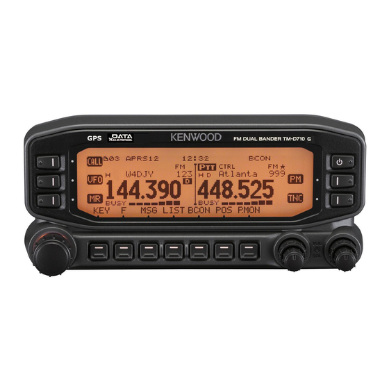
TM-D710GA/ TM-D710GE
144/440 MHz FM DUAL BANDER/
144/430 MHz FM DUAL BANDER
INSTRUCTION MANUAL
144/440 MHz FM DOUBLE BANDE/
144/430 MHz FM DOUBLE BANDE
MODE D'EMPLOI
DOBLE BANDA DE 144/440 MHz EN FM/
DOBLE BANDA DE 144/430 MHz EN FM
MANUAL DE INSTRUCCIONES
Only basic operations are explained in this instruction manual.
For a detailed explanation on the operations, refer to the PDF fi le
supplied on the CD-ROM.
Seules les fonctions de base sont expliquées dans ce mode
d'emploi. Pour le détail sur les autres opérations, reportez-vous
au fi chier PDF à votre disposition sur le CD-ROM.
En este manual de instrucciones solamente se explican las
operaciones básicas. Si desea obtener una descripción detallada
de las operaciones, consulte el archivo PDF correspondiente
incluido en el CD-ROM.
© B62-2562-00 (K, E)
09 08 07 06 05 04 03 02 01 00
Advertisement
Table of Contents

Related Manuals for Kenwood TM-D710GA


Summary of Contents for Kenwood TM-D710GA
-
Page 1: Instruction Manual
TM-D710GA/ TM-D710GE 144/440 MHz FM DUAL BANDER/ 144/430 MHz FM DUAL BANDER INSTRUCTION MANUAL 144/440 MHz FM DOUBLE BANDE/ 144/430 MHz FM DOUBLE BANDE MODE D’EMPLOI DOBLE BANDA DE 144/440 MHz EN FM/ DOBLE BANDA DE 144/430 MHz EN FM MANUAL DE INSTRUCCIONES Only basic operations are explained in this instruction manual. - Page 3 This equipment requires a licence and is intended for use in the countries as below. ISO3166 Firmware Copyrights The title to and ownership of copyrights for fi rmware embedded in KENWOOD product memories are reserved for JVC KENWOOD Corporation.
- Page 4 THANK YOU We are grateful you decided to purchase this KENWOOD FM transceiver. KENWOOD always provides Amateur Radio products which surprise and excite serious hobbyists. This transceiver is no exception. KENWOOD believes that this product will satisfy your requirements for both voice and data communications.
-
Page 5: Notices To The User
NOTICES TO THE USER One or more of the following statements may be applicable: FCC WARNING This equipment generates or uses radio frequency energy. Changes or modifi cations to this equipment may cause harmful interference unless the modifi cations are expressly approved in the instruction manual. - Page 6 Check the battery polarity and voltage of the vehicle before installing the transceiver. ◆ Use only the supplied DC power cable or a KENWOOD optional DC power cable. ◆ Do not insert metal objects into the cooling fan.
-
Page 7: Table Of Contents
CONTENTS PREPARATION ....................1 SUPPLIED ACCESSORIES ............... 1 MOBILE INSTALLATION ................2 TX/RX Unit Installation ................2 Operation Panel Installation ..............3 Power Cable Connection ............... 3 FIXED STATION ..................4 Operation Panel Installation ..............4 Power Cable Connection ............... 5 REPLACING FUSES .................. - Page 8 VGS-1 (OPTIONAL) OPERATION 13_VGS_EN.pdf 14_CROSS BAND_REP_TM-D710GA_ CCROSS-BAND/ LOCKED-BAND OPERATION (TM-D710GA ONLY) EN.pdf WIRELESS OPERATION (TM-D710GA ONLY) 15_WIRELESS_TM-D710GA_EN.pdf WEATHER ALERT (TM-D710GA ONLY) 16_WEATHER ALERT_TM-D710GA_EN.pdf SKY COMMAND SYSTEM II 17_SKY COMMAND_EN.pdf Note: Operation fi les are available in PDF fi le format. To read the fi les, you must use Adobe ®...
-
Page 9: Preparation
PREPARATION SUPPLIED ACCESSORIES Item Quantity Microphone Microphone hanger DC power cable (with 20 A fuses) Mounting bracket Screw set Modular plug cable (for PANEL jacks) Line fi lter Cable with a 2.5 mm (1/10") 3-conductor plug (for GPS jack) Base stand Panel holder Panel bracket Fuse (15 A) -
Page 10: Mobile Installation
MOBILE INSTALLATION ■ TX/ RX Unit Installation Select a safe, convenient location inside your vehicle that will minimize danger to your passengers and yourself while the vehicle is in motion. Consider installing the transceiver under the dash in front of the passenger seat so that knees or legs will not strike the radio during sudden braking of your vehicle. -
Page 11: Operation Panel Installation
■ Operation Panel Installation Tapping screw Note: Install the operation panel in a location where it (4 mm x 12 mm) can easily receive satellite signals. Install the operation panel so that it is standing perpendicular. Flat washer Panel Do not install the bracket close to an air bag. bracket 1 Clean and dry the installation location. -
Page 12: Fixed Station
Note: If you use the transceiver for a long period when the vehicle battery is not fully charged or when the engine is OFF, the battery may become discharged and will not have suffi cient reserves to start the vehicle. Avoid using the transceiver under these conditions. 1 Route the DC power cable supplied with the transceiver directly to the vehicle’s battery terminals using the shortest path from the transceiver. -
Page 13: Power Cable Connection
■ Power Cable Connection In order to use this transceiver for fi xed station operation, you will need a separate 13.8 V DC power supply that must be purchased separately. The recommended current capacity of the power supply is 13 A. Note: Do not plug the DC power supply into an AC outlet until you make all connections. -
Page 14: Replacing Fuses
If the fuse blows, determine the cause, then correct the problem. After the problem is resolved, replace the fuse. If newly installed fuses continue to blow, disconnect the power cable and contact your authorized KENWOOD dealer or an authorized KENWOOD service center for assistance. -
Page 15: Antenna Connection
ANTENNA CONNECTION Before operating, you must fi rst install an effi cient, well-tuned antenna. The success of your installation will depend largely on the type of antenna and its correct installation. The transceiver can give excellent results if the antenna system and its installation are given careful attention. -
Page 16: Getting Acquainted
GETTING ACQUAINTED OPERATION PANEL (FRONT) ■ In Normal Mode a CALL Press [CALL] to select the Call channel. Press [CALL] (1s) to start Call scan. b VFO Press [VFO] to enter VFO mode, then rotate the Tuning control to select an operating frequency. - Page 17 Low Power ➡ High Power. j PF1 Press [PF1] to activate its programmable function. The default function is “Weather Channel” (TM-D710GA)/“Frequency Band Select” (TM-D710GE). k PF2 Press [PF2] to activate its programmable function. The default function is “Operation Band Select”.
-
Page 18: In Function Mode
■ In Function Mode a C.IN Press [C.IN] to store the current operating frequency to the Call channel. b M>V Press [M>V] to copy the current Memory channel or Call channel to the VFO (memory shift). c M.IN Select a Memory channel, then press [M.IN] to store the current operating frequency in the Memory channel. -
Page 19: Operation Panel (Rear & Left)
k SQL Control Rotate the [SQL] control to adjust the squelch level. Clockwise tightens the squelch and counterclockwise opens the squelch. l DX Press [DX] to turn the DX PacketClusters Monitor ON and OFF. m P.IN Press [P.IN] to enter PM Channel registration mode. Press [ ] to turn the transceiver power ON and OFF. -
Page 20: Display
Indicator Description Clock display Appears when there is a transmission band available. Blinks when the cross-band repeater is ON (TM-D710GA only). Appears when there is an operation band available. Blinks when the wireless remote control is ON (TM-D710GA only). Appears when the Tone function is ON. - Page 21 Appears when the Key Lock function is ON. Displays the PM channel number. Appears when Weather Alert is ON. Blinks when receiving a signal (TM-D710GA only). Appears when a message is received. Appears when the Beacon type is set to “APRS”.
- Page 22 Indicator Description Appears while in PACKET mode. Appears when the packet transfer rate is set to 1200 bps. Appears when the packet transfer rate is set to 9600 bps. Appears when the Beacon function is ON. Appears when the external GPS is ON. Blinks while positioning.
-
Page 23: Tx/ Rx Unit Rear Panel
TX/ RX UNIT REAR PANEL a ANT Connect an SO-239/M-type (TM-D710GA) or N-type (TM-D710GE) external antenna to this terminal. When making test transmissions, connect a dummy load in place of the antenna. The antenna system or load should have an impedance of 50 . -
Page 24: Microphone (Mc-59)
MICROPHONE (MC-59) Microphone Jack Keypad serial data No Connection MIC, 600 impedance GND (MIC) DC 8 V, 100 mA max No Connection a PTT switch Press and hold, then speak into the microphone to transmit. b DTMF keypad Press these keys to make DTMF calls, enter frequencies, or enter characters. c CALL/ A Functions the same as the transceiver front panel [CALL] key. -
Page 25: Basic Operations
BASIC OPERATIONS SWITCHING THE POWER ON/ OFF Press the [ ] switch to switch the transceiver ON. • The power on message momentarily appears on the display. • If the transceiver power on password has been activated {Menu No.998}, you must fi rst enter your password before you can operate the transceiver. -
Page 26: Adjusting The Squelch
ADJUSTING THE SQUELCH Squelch is used to mute the speaker when no signals are present. With the squelch level set correctly, you will hear sound only while actually receiving a signal. The higher the squelch level selected, the stronger the signals must be in order to hear them. - Page 27 Pressing [PF2] allows you to switch the operating band between bands A and B, while maintaining the original band as the transmit band. Band A is the transmit band and band B is the operating band: Band A is both the transmit and operating band:...
-
Page 28: Selecting Dual Band Mode/ Single Band Mode
Band A: 118 >> 144 (default) >> 220 >> 300 >> 430/440 (MHz). • Band B: 144 >> 220 >> 300 >> 430/440 (default) >> 1200 (MHz). Note: TM-D710GE models use the 430 MHz band and TM-D710GA models use the 440 MHz band. -
Page 29: Selecting An Operating Mode
• 430/440 MHz: 400 ~ 523.995 MHz • 1200 MHz: 800 ~ 1299.990 MHz (TM-D710GA: excluding cellular band) SELECTING AN OPERATING MODE There are 3 operating modes available to choose from: VFO mode, Memory Channel mode, and Call Channel mode. -
Page 30: Memory Channel Mode
■ Memory Channel Mode Memory Channel mode allows you to quickly select a frequently used frequency and related data which you have saved in the transceiver memory. 1 Press [MR] to enter Memory Channel mode. 2 Rotate the Tuning control to select your desired Memory channel. ■... -
Page 31: Transmitting
TRANSMITTING 1 Select your desired band and frequency/channel. 2 Press and hold the microphone [PTT] switch and speak into the microphone to transmit. • icon and the RF power meter appear on the display for the selected transmit band. The RF power meter shows the relative transmit output power. •... -
Page 32: Menu Mode
MENU MODE Many functions on this transceiver are selected or confi gured through the Menu instead of physical controls. Once you become familiar with the Menu system, you will appreciate the versatility it offers. MENU ACCESS 1 Press [F], Tuning control to access the Menu. •... -
Page 33: Menu Configuration
MENU CONFIGURATION AUDIO Menu Setting Default Display Description Values Setting KEY BEEP Beep sound OFF/ ON LEVEL 1 ~ BEEP VOLUME Beep volume level LEVEL 5 LEVEL 7 External speaker output MODE 1/ EXT.SPEAKER MODE 1 mode MODE 2 OFF/ AUTO/ ANNOUNCE Voice announcement mode AUTO... - Page 34 Time-out timer 3/ 5/ 10 min 10 min HIGH (TM-D710GE) MICROPHONE HIGH/ Microphone Sensitivity SENSITIVITY MEDIUM/ LOW MEDIUM (TM-D710GA) WEATHER ALERT Weather alert OFF/ ON AUTO WEATHER Auto weather channel scan OFF/ 15/ 30 / time 60 min SCAN MEMORY...
- Page 35 DTMF Menu Setting Default Display Description Values Setting DTMF HOLD DTMF transmission hold OFF/ ON Up to 8 characters for DTMF memory DTMF MEMORY DTMF memory – name Up to 16 digits for DTMF code DTMF memory DTMF SPEED FAST/ SLOW FAST transmission speed 100/ 250/ 500/...
- Page 36 Menu Setting Default Display Description Values Setting SETUP 1 DATUM Datum WGS-84/ TOKYO WGS-84 Satellite Based SBAS OFF/ ON Augmentation System COM OUTPUT GPS data output to PC OFF/ ON SETUP 2 $GPGGA/ $GPGLL/ $GPGGA $GPGSA/ $GPGSA SENTENCE Sentence $GPGSV/ $GPGSV $GPRMC/ $GPRMC...
- Page 37 (PeetBros) OFF/ OUTPUT GPS data output type WAYPOINT/ DGPS WAYPOINT NMEA/ FORMAT Way point format MAGELLAN/ NMEA KENWOOD 6-CHAR ~ NAME Way point name 6-CHAR 9-CHAR ALL/ LOCAL/ OUTPUT Way point output type FILTERED COM PORT OUTPUT COM port output...
- Page 38 OBJECT/ TYPE Packet fi lter type Checked all NAVITRA/ 1-WAY/ OTHERS STATION ICON STATION ICON Station icon See explanation (KENWOOD icon) BEACON TX ALGORITHM MANUAL/ METHOD Method PTT/ AUTO/ MANUAL SmartBeaconing 0.2/ 0.5/ 1/ 3/ INITIAL INTERVAL Initial interval time...
- Page 39 APRS Menu Setting Default Display Description Values Setting VOICE ALERT VOICE ALERT Voice alert OFF/ ON CTCSS FREQUENCY CTCSS frequency See explanation 100.0 Hz WEATHER STATION Weather TX OFF/ ON TX INTERVAL Weather TX interval time 5/ 10/ 30 min 5 min DIGIPEAT (MY CALL) DIGIPEAT...
- Page 40 CHANGE COLOR Change color OFF/ ON 3/ 5/ 10 sec/ INTERRUPT TIME Interrupt time 10 sec INFINITE DISPLAY UNIT 1 mi/h, mile (TM-D710GA) mi/h, mile/ km/h, SPEED, DISTANCE Speed/ distance km/ knots, nm km/h, km (TM-D710GE) feet, inch (TM-D710GA) ALTITUDE, RAIN...
- Page 41 APRS Menu Setting Default Display Description Values Setting NAVITRA GROUP GROUP MODE Group mode OFF/ ON GROUP CODE Group code 3 characters NAVITRA MESSAGE Up to 20 − MESSAGE Message characters SMARTBEACONING 1 2 ~ 30 <mi/h, LOW SPEED Low speed setting km/h, knots>...
- Page 42 LEVEL 1 ~ CONTRAST Display contrast LEVEL 8 LEVEL 16 DISPLAY REVERSE POSITIVE/ Display reverse mode POSITIVE NEGATIVE MODE WX CH (TM-D710GA) PF1 key programmable PANEL PF1 function value explanation FRQ.BAND (TM-D710GE) PF2 key programmable PANEL PF2 CTRL function value explanation...
- Page 43 AUX 2 Menu Setting Default Display Description Values Setting OFF/ 30/ 60/ Auto Power Off time 90/ 120/ 180 A-BAND/ B-BAND/ External TNC data band TX:A-BAND EXT. DATA BAND B-BAND type RX:B-BAND/ RX:A-BAND TX:B-BAND External TNC data EXT. DATA SPEED 1200/ 9600 bps 1200 bps communications speed...
-
Page 44: Character Entry
Available only when the optional VGS-1 unit is installed in the transceiver. Available only for TM-D710GA. Note: The default settings are subject to change. CHARACTER ENTRY Certain menus require you to enter characters, such as the power on message and memory names. When character entry is required, a cursor will appear on the display. -
Page 45: Microphone Keypad Character Entry
■ Microphone Keypad Character Entry The microphone keys can also be used to enter characters. Refer to the table below for characters corresponding to microphone keys. Character Display (with Character Display (with each press of the key) each press of the key) (space) Not used –... -
Page 46: Options
Print/export memory and various settings in html (TravelPlus for Repeaters is a trademark of ARRL.) To download the MCP-6A software, go to: http://www.kenwood.com/i/products/info/amateur/software_download.html Note: This URL may change without notice. ■ Using the MCP-6A Software 1 Follow the directions of the installer to install the software. -
Page 47: Connecting The Pg-5G/ Pg-5H Interface Cables
CONNECTING THE PG-5G/ PG-5H INTERFACE CABLES The PG-5G package comes with cable a (below). The PG-5H packages comes with cables a and b (below). a Data communications cable DATA terminal pin To PC audio terminal b Serial communications cable To PC 9-pin D-SUB terminal Data communications cable pin confi... -
Page 48: Connecting The Pg-5F Extension Cable
CONNECTING THE PG-5F EXTENSION CABLE Using two PG-5F kits, you can extend the cables to the maximum length. (Components marked with an asterisk * are included in the PG-5F kit.) ■ Connecting Using a Single Extension Kit External speakers Microphone * DC power cables (6 m) Speaker cables (4 m) * Extension... -
Page 49: Installing The Vgs-1 Unit
INSTALLING THE VGS-1 UNIT Follow the instructions below to install the VGS-1 unit. 1 Remove the 8 screws from the cover of the base unit, then remove the cover itself from the unit. Cushion 2 From the 5 black cushions supplied with the VGS-1, select the thickest rectangular cushion (20 x 30 x 12 mm) and attach it to the top surface of the VGS-1 unit. -
Page 50: Maintenance
Don’t return accessory items unless you feel they are directly related to the service problem. You may return this product for service to the authorized KENWOOD dealer from whom you purchased it, or any authorized KENWOOD service center. Please do not send subassemblies or printed circuit boards;... -
Page 51: Troubleshooting
TROUBLESHOOTING The problems described in this table are commonly encountered operational malfunctions and are usually not caused by circuit failure. Problem Probable Cause Corrective Action The transceiver will 1 The power cable 1 Connect the supplied DC not power up after was connected power cable correctly (red connecting a 13.8 V... - Page 52 Problem Probable Cause Corrective Action “MCP ERR” appears on 1 There is a problem 1 Ensure that the connection the display. (MCP-6A with the connection between the TM-D710G communications error) between the and the PC is correct. TM-D710G and the 2 The PC is performing 2 Shut down other software a large amount of...
-
Page 53: Specifications
Band A 118 ~ 524 MHz Frequency 136 ~ 524 MHz range Band B 800 ~ 1300 MHz (TM-D710GA: excluding cellular band) Mode F1D/ F2D/ F3E 50 Antenna impedance Operating temperature range –20°C ~ +60°C (–4°F ~ +140°F) Power requirement 13.8 V DC ±15% (Negative ground) - Page 54 Transmitter 50 W RF power Approx. 10 W output Approx. 5 W Modulation Reactance modulation Maximum frequency deviation Within ±5 kHz Spurious radiation Less than –60 dB Modulation distortion (300 Hz ~ 3 kHz) Less than 3% 600 Microphone impedance Receiver Circuitry Double super heterodyne...