Table of Contents
Advertisement
Advertisement
Table of Contents

Related Manuals for Foxconn P45A Series


Summary of Contents for Foxconn P45A Series
- Page 1 P45A Series Motherboard User’s Manual...
- Page 2 Statement: This manual is the intellectual property of Foxconn, Inc. Although the information in this manual may be changed or modified at any time, Foxconn does not obligate itself to inform the user of these changes. Trademark: All trademarks are the property of their respective owners.
-
Page 3: Declaration Of Conformity
HON HAI PRECISION INDUSTRY COMPANY LTD 66 , CHUNG SHAN RD., TU-CHENG INDUSTRIAL DISTRICT, TAIPEI HSIEN, TAIWAN, R.O.C. declares that the product P45A/P45A-S Motherboard is in conformity with (reference to the specification under which conformity is declared in accordance with 89/336 EEC-EMC Directive) ■... - Page 4 Declaration of conformity Trade Name: FOXCONN Model Name: P45A/P45A-S Responsible Party: PCE Industry Inc. Address: 458 E. Lambert Rd. Fullerton, CA 92835 Telephone: 714-738-8868 Facsimile: 714-738-8838 Equipment Classification: FCC Class B Subassembly Type of Product: Motherboard Manufacturer: HON HAI PRECISION INDUSTRY...
-
Page 5: Installation Precautions
Installation Precautions ■ Electrostatic discharge (ESD) is the sudden and momentary electric current that flows between two objects at different electrical potentials. Normally it comes out as a spark which will quickly damage your electronic equipment. Please wear an electrostatic discharge (ESD) wrist strap when handling components such as a motherboard, CPU or memory. -
Page 6: Table Of Contents
TAble of CoNTeNTS Chapter 1 Product Introduction Product Specifications ................2 Layout.......................4 Back Panel Connectors ................5 Chapter 2 Hardware Install Install the CPU and CPU Cooler ..............8 Install the Memory .................. 11 Install an Expansion Card ..............13 Install other Internal Connectors ............14 Jumpers ....................18 Chapter 3 bIoS Setup Enter BIOS Setup ...................20... - Page 7 Online Update ..................60 Configure ..................63 About & Help ..................65 FOX LOGO .....................66 FOX DMI ....................67 Chapter 5 RAID Configuration RAID Configuration Introduction.............70 Intel® Matrix Storage Manager ..............72 Create a RAID Driver Diskette ...............73 BIOS Configuration ................75 Create RAID in BIOS................75 Install a New Windows XP ..............99 Existing Windows XP with RAID built as data storage ......103 Appendix - Crossfire...
- Page 8 With advanced overclocking capability and a range of connectivity features for today multi-media computing requirements, P45A/ P45A-S enables you to unleash more power from your computer. This chapter includes the following information: ■...
-
Page 9: Product Specifications
Celeron Dual-core, Celeron processors Front Side Bus 1333/1066/800MHz FSB North Bridge: Intel ® P45 Chipset South Bridge: Intel ® ICH10R (P45A-S) Intel ® ICH10 (P45A) Memory 4 x 240-pin DDR2 DIMM sockets Support up to 8GB of system memory Dual channel DDR2 1066(oc*)/800/667MHz architecture (oc*: Overclocking) - Page 10 1 x PS/2 mouse port 1 x ESATA port (Controlled by Jmicron361) 1 x Coaxial S/PDIF out port 1 x Serial port 1 x 1394a port (P45A-S) 4 x USB 2.0 ports 1 x RJ-45 LAN port 8-channel audio ports...
-
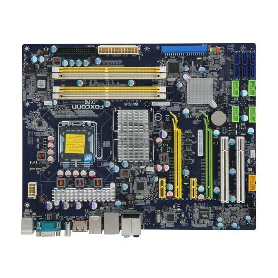
Page 11: Layout
1-2 layout 14. South Bridge: Intel ® ICH10R(P45A-S) 1. 8-pin ATX 12V Power Connector 2. North Bridge: Intel ® P45 Intel ® ICH10(P45A) 3. NB_FAN Header 15. Front Panel Connector 4. PCI Express x1 Slots 16. IDE Connector 5. PCI Express x16 Slots 17. -
Page 12: Back Panel Connectors
The USB port supports the USB 2.0/1.1 specification. Use this port for USB devices such as an USB keyboard/mouse, USB printer, USB flash drive and etc. 7. 1394a Port (P45A-S) This port is used to connect a 1394a device. 8. RJ-45 lAN Port The Ethernet LAN port provides Internet connection at up to 10/100/1000Mb/s data rate. - Page 13 9. Audio Ports For the definition of each audio port, please refer to the table below : Port 2-channel 4-channel 5.1-channel 7.1-channel Blue Line In Line In Line In Line In Green Line Out Front Speaker Out Front Speaker Out Front Speaker Out Pink Microphone In...
- Page 14 This chapter introduces the hardware installation process, including the installation of the CPU, memory, power supply, slots, pin headers and the mounting of jumpers. Caution should be exercised during the installation of these modules. Please refer to the motherboard layout prior to any installation and read the contents in this chapter carefully.
-
Page 15: Install The Cpu And Cpu Cooler
2-1 Install the CPU and CPU Cooler Read the following guidelines before you begin to install the CPU : ■ Make sure that the motherboard supports the CPU. ■ Always turn off the computer and unplug the power cord from the power supply before installing the CPU to prevent hardware damage. - Page 16 Follow the steps to install the CPU onto the CPU socket : Before installing the CPU, make sure to turn off the computer and unplug the power cord from the power outlet to prevent damage to the CPU. 2. Release the CPU socket lever. 1.
-
Page 17: Install The Cpu Cooler
Install the CPU Cooler Follow the steps below to correctly install the CPU cooler on the motherboard. (The following procedures use Foxconn cooler as the example.) 1. Apply and spread an even thermal 2. Place the four bolts of the CPU grease on the surface of CPU. -
Page 18: Install The Memory
2-2 Install the Memory Read the following guidelines before you begin to install the memory : ■ Make sure that the motherboard supports the memory. It is recommended that memory of the same capacity, brand, speed, and chips be used. ■... -
Page 19: Installing A Memory
Installing a Memory Before installing a memory module, make sure to turn off the computer and unplug the power cord from the power outlet to prevent damage to the memory module. Be sure to install DDR2 DIMMs on this motherboard. Notch If you take a look at front side of memory module, it has asymmetric pin counts on both sides separated by a notch in the middle, so it can only fit in one direction. -
Page 20: Install An Expansion Card
2-3 Install an expansion Card ■ Make sure the motherboard supports the expansion card. Carefully read the manual that came with your expansion card. ■ Always turn off the computer and unplug the power cord from the power outlet before installing an expansion card to prevent hardware damage. -
Page 21: Install Other Internal Connectors
2-4 Install other Internal Connectors Power Connectors This motherboard uses an ATX power supply. In order not to damage any device, make sure all the devices have been installed properly before applying the power supply. 24-pin ATX Power Connector : PWR1 PWR1 is the ATX power supply connector. - Page 22 Connect a 4-pin power plug We recommend you using an 8-pin ATX 12V power supply. If you are using a 4-pin power supply, you need to align the ATX power connector according to the picture on the right. Audio Connector : f_AUDIo PORT1_L AUD_GND The audio connector supports HD Audio standard.
- Page 23 front Panel Connector : fP1 This motherboard includes one connector for connecting the front panel switch and LED Indicators. HDD-LED PWR-LED Hard Disk leD Connector (HDD-leD) RESET-SW PWR-SW Connect to the chassis front panel IDE indicator LED. It EMPTY indicates the active status of the hard disks. This 2-pin connector is directional with +/- sign.
- Page 24 1394a Connector : f_1394 (P45A-S) The 1394a expansion cable can be connected to either the front (provided that the front panel of your chassis TPA+ TPA- is equipped with the appropriate interface) or real panel TPB+ TPB- of the chassis.
-
Page 25: Jumpers
2-5 Jumpers For some features needed, users can change the jumper settings on this motherboard to modify them. This section explains how to use the various functions of this motherboard by changing the jumper settings. Users should read the following content carefully prior to modifying any jumper setting. Description of Jumpers 1. - Page 26 This chapter tells how to change system settings through the BIOS Setup menus. Detailed descriptions of the BIOS parameters are also provided. You have to run the Setup Program when the following cases occur : 1. An error message appears on the screen during the system Power On Self Test (POST) process.
-
Page 27: Enter Bios Setup
enter bIoS Setup The BIOS is the communication bridge between hardware and software, correctly setting up the BIOS parameters is critical to maintain optimal system performance. Power on the computer, when the message "Press <Del> to enter Setup, <esc> to boot menu" appears at the bottom of the screen, you can press <DEL>... - Page 28 ► Power Management Setup All the items related with Green function features can be setup through this menu. ► PnP/PCI Configuration PCI/PnP features, such as graphics card select and bus master ...etc. can be modified through this option. ► PC Health Status This setup enables you to read/change fan speeds, and displays temperatures and voltages of your CPU/System.
-
Page 29: System Information
System Information This sub-menu is used to set up the standard BIOS features, such as the date, time, floppy drive and so on. Use the arrow up/down keys to select an item, then use the <+> or <-> keys to change the setting. -
Page 30: Bios Version
► Keyboard The system boot will not stop for a keyboard error if you enabled this item. ► Mouse The system boot will not stop for a mouse error if you enabled this item. ► Floppy The system boot will not stop for a floppy error if you enabled this item. ►... -
Page 31: Advanced Bios Features
Advanced BIOS Features CMOS Setup Utility - Copyright (C) 1985-2005, American Megatrends, Inc. Advanced BIOS Features ► CPU Configuration [Press Enter] Help Item [Press Enter] ► Boot Device Priority [Press Enter] ► Hard Disk Drives [Press Enter] Configure CPU. ► Removable Drives [Press Enter] ►... -
Page 32: Hardware Prefetcher
CPU Configuration CMOS Setup Utility - Copyright (C) 1985-2005, American Megatrends, Inc. CPU Configuration Manufacturer : Intel Help Item Intel(R) Core(TM)2 Quad CPU Q9450 @2.66GHz Speed : 2.66GHz This can enable FSB Speed : 1333MHz in order to enable or Cache L1 :128KB disable the “Enhanced... - Page 33 ► Execute Disable Bit This item is used to enable/disable the Execute Disable Bit feature. Intel's Execute Disable Bit functionality can help prevent certain classes of malicious buffer overflow attacks when combined with a supporting operating system. Execute Disable Bit allows the processor to classify areas in memory by where application code can execute and where it cannot.
-
Page 34: Central Control Unit
Central Control Unit CMOS Setup Utility - Copyright (C) 1985-2005, American Megatrends, Inc. Central Control Unit [Disabled] Smart Power LED Help Item Options ► O.C. Configuration [Press Enter] ► O.V. Configuration [Press Enter] Disabled Enabled ↑↓←→:Move Enter:Select +/-/:Value F10:Save ESC:Exit F1:General Help F9:Optimized Defaults ►... -
Page 35: Spread Spectrum
O.C. Configuration CMOS Setup Utility - Copyright (C) 1985-2005, American Megatrends, Inc. O.C. Configuration Spread Spectrum Help Item [Enabled] CPU Clock [333] Options PCI Express Clock [100] CPU: DRAM Clock Ratio [Disabled] Target Memory Speed :667MHz Disabled *********** Over Clock Step Up*********** Enabled Start CPU Clock: 333MHz Next CPU Clock: 338MHz... - Page 36 ► Run Setup Over Clock This setting is used to detect a CPU clock value which can be run in your overcolck system without risk. Select [OK], and press [Enter], then BIOS will increase CPU clock step by step, drive the system to its maximal speed until it can not drive any more and restarts itself. During the process, you can press [q] or [Q] to stop it.
- Page 37 O.V. Configuration CMOS Setup Utility - Copyright (C) 1985-2005, American Megatrends, Inc. O.V. Configuration VCore Offset Control Help Item VRAM Voltage Control DRAM Approx Voltage: 1.758V+0.048Vx3=1.902V Allows BIOS to set MCH Voltage Control I CPU voltage, MCH Approx Voltage: 1.018V+0.028Vx3=1.102V 6.25mV per step.
-
Page 38: Advanced Chipset Features
Advanced Chipset Features CMOS Setup Utility - Copyright (C) 1985-2005, American Megatrends, Inc. Advanced Chipset Features Advanced Chipset Settings Help Item WARNING: Setting wrong values in below sections Configure North Bridge may cause system to malfunction. features. ► North Bridge Configuration [Press Enter] [Press Enter] ►... -
Page 39: South Bridge Configuration
sociate addresses with those storage cells. Of course, that only works if you're using a 64-bit (or 32bit physical address extension (PAE) enabled) OS that can deal with physical addresses larger than 32 bits. Once this option is enabled, the BIOS can see maximum 8192 MB of memory. ►... -
Page 40: Integrated Peripherals
Integrated Peripherals CMOS Setup Utility - Copyright (C) 1985-2008, American Megatrends, Inc. Integrated Peripherals ► OnChip ATA Devices [Press Enter] [Press Enter] Help Item ► OnBoard Devices [Press Enter] ► SuperIO Configuration [Press Enter] OnChip ATA Devices ► USB Configuration [Press Enter] ↑↓←→:Move Enter:Select +/-/:Value F10:Save ESC:Exit... -
Page 41: Onboard Devices
level interface for a Host Controller for Serial ATA. The specification includes a description of the hardware/software interface between system software and the host controller hardware. AHCI provides more advanced features including SATA features, but some SATA drives may not support AHCI, unless they are labeled with AHCI support in its specification. If your motherboard supporting AHCI, and you have a SATA device, which also supports AHCI, then you can select IDE option to have fair performance (only PATA, SATA level), or you can select AHCI to get its best performance. -
Page 42: Superio Configuration
empty PCI slot to reduce EMI (Electromagnetic Interference). SuperIO Configuration CMOS Setup Utility - Copyright (C) 1985-2005, American Megatrends, Inc. SuperIO Configuration OnBoard Floppy Controller [Enabled] Help Item [Enabled] Serial Port Address [Enabled] IrDA Function [Enabled] Allows BIOS to Enable IrDA Duplex Mode [Half Duplex] or disable floppy... -
Page 43: Usb Configuration
USB Configuration CMOS Setup Utility - Copyright (C) 1985-2005, American Megatrends, Inc. USB Configuration USB Devices Enabled : Help Item None Enables support for legacy USB. Legacy USB Support [Enabled] [Enabled] USB 2.0 Controller Mode [High Speed] BIOS EHCI Hand-Off [Enabled] ↑↓←→:Move Enter:Select +/-/:Value F10:Save ESC:Exit... -
Page 44: Power Management Setup
Power Management Setup CMOS Setup Utility - Copyright (C) 1985-2005, American Megatrends, Inc. Power Management Setup ACPI Suspend Type S3(STR) Help Item [S1 (POS)] Power On after Power Fail [Power Off] Wake On PME [Enabled] Select the ACPI state. Wake On USB Devices [Enabled] Wake On PS2 Keyboard [Enabled]... - Page 45 computer before it entering STR will be saved in memory, and the computer can quickly return to previous state when the STR function wakes. ► Power On after Power Fail This item is used to set which state the PC will take with when it resumes after an AC power loss.
-
Page 46: Pnp/Pci Configuration
PnP/PCI Configuration CMOS Setup Utility - Copyright (C) 1985-2005, American Megatrends, Inc. PnP/PCI Configuration Initial Graphics Adapter Help Item [PEG/PCI] PCI IDE BusMaster [Enabled] Select which graphics controller is used as the primary boot device. ↑↓←→:Move Enter:Select +/-/:Value F10:Save ESC:Exit F1:General Help F9:Optimized Defaults ►... -
Page 47: Pc Health Status
PC Health Status CMOS Setup Utility - Copyright (C) 1985-2005, American Megatrends, Inc. PC Health Status CPU Temperature C/127 Help Item System Temperature C/73 Options CPU Fan Speed :3154 RPM System Fan Speed :N/A Disabled N/B Fan Speed :N/A Enabled Reset Vcore :1.232 V... -
Page 48: Bios Security Features
bIoS Security features CMOS Setup Utility - Copyright (C) 1985-2005, American Megatrends, Inc. BIOS Security Features Supervisor Password : Not Installed Help Item User Password : Not Installed [Press Enter] Change Supervisor Password [Press Enter] Install or change the Change User Password [Press Enter] password. -
Page 49: Load Optimal Defaults
load optimal Defaults Optimal defaults are the best settings of this motherboard. Always load the Optimal defaults after updating the BIOS or after clearing the CMOS Load Optimal Defaults? values. Select this option and press Enter, it will pop out a dialogue box to let [OK] [OK] [Cancel]... - Page 50 The utility CD that came with the motherboard contains useful software and several utility drivers that enhance the motherboard features. This chapter includes the following information: ■ Utility CD content ■ Install driver and utility ■ FOX ONE ■ FOX LiveUpdate ■...
-
Page 51: Utility Cd Content
Utility CD content This motherboard comes with one Utility CD. You can simply put it into your CD/DVD-ROM drive, and the main menu will be displayed on your PC screen to guide you how to install. 1. Install Driver Use these options to install all the drivers for your system. You should install the drivers in order, and you need to restart your computer after all the drivers have been installed. -
Page 52: Install Driver And Utility
Step by Step Automatic Installation by One Click Exit the program Drop to System Tray Click to visit Select to Install Select to Browse CD Foxconn's Utilities Install Drivers website 2. Install Utility You can select the specific utility to install. -
Page 53: Fox One
foX oNe FOX ONE is a powerful utility for easily modifying system settings. It also allows users to monitor various temperature values, voltage values, frequencies and fan speeds at any time. With FOX ONE, you can : ■ Modify system performance settings, such as the CPU and memory bus speeds, CPU voltages, fan speeds, and other system performance options. -
Page 54: Main Page
1. Main Page Show CPU Toolbar Information Alert Lamp Switch Button Skin Button Exit Minimum Configuration Homepage Monitor Frequency/Voltage/Fan speed/Temperature value Toolbar Use the toolbar to navigate to other pages. Alert lamp When the system is in healthy state, the color of alert lamp is green. When the system is in abnormal state, the alert lamp color is red. - Page 55 Click this button to exit the program. Minimum Click this button to drop the FOX ONE to Windows system tray located at the lower right corner of your screen. Homepage Click this button to visit Foxconn motherboard website : http://www.foxconnchannel.com...
- Page 56 Configuration This menu allows you to configure : 1). Monitor interval (ms) : This is to define the interval of different messages of system settings which are to be displayed on Simple Mode screen. Minimum value is 1 second. 2). Simple Mode : To select which message of system settings are to be displayed in the Simple Mode.
- Page 57 Step 1 : Click Calibration icon, a message pops out to ask for continue. Select Yes. Step 2 : After data is collected, it will ask you to restart your computer now. Later on, when the FOX ONE program is activated, and F.I.S. feature (in CPU Page) is also enabled, FOX ONE will automatically adjust your CPU clock according to your system loadings.
-
Page 58: Cpu Control
2. CPU Page - CPU Control This page lets you select (or overclock) CPU clock to meet the current performance level of the system. The fastest and suitable CPU clock running for current system can be calculated by FOX ONE automatically or manually input by yourselves. Manual : You can press the up/down button to adjust your CPU clock. - Page 59 You can see the system is raising CPU clock until the system hangs. Push RESET button on the front panel of your system to restart the computer. Run FOX ONE program again, it will inform you the previous test found that 255MHz is the recommended CPU clock for your system.
-
Page 60: Frequency Control
FOX Intelligent Stepping (F.I.S., Optional) Select FOX Intelligent Stepping will allow your system to automatically adjust your CPU clock rate based on different system loadings. For example, if you select Power Gaming, CPU clock will be driven to run at its maximum speed. While in Energy Saving, CPU will lower down its speed to a minimum. -
Page 61: Limit Setting
4. Limit Setting 4.1 Limit Setting - CPU Temperature This page lets you to set CPU high limit temperature and enable the alert function. Go to Limit Setting Show current CPU page temperature value Enable alert function when the CPU temperature is higher than high limit value Show current high... - Page 62 4.3 Limit Setting - CPU Fan This page lets you to set CPU fan low limit rpm and enable the alert function. Show current CPU fan rpm value Enable alert function when the CPU fan runs slower than the low limit rpm value Show current low limit rpm value of CPU fan...
-
Page 63: Voltage Control
4.5 Limit Setting - FAN1 Fan This page lets you to set FAN1 fan low limit rpm and enable the alert function. Show current FAN1 fan rpm value Enable alert function when the FAN1 fan runs slower than low limit rpm value Show current low limit rpm value of FAN1 fan Set low limit rpm by... -
Page 64: Fan Control
6. Fan Page - Fan Control This page lets you enable Smart Fan function or set the fan speed by manual. When Smart Fan is selected, you must use a 4-pin CPU cooler in your system. Go to Fan page Enable or disable smart fan function Set fan speed by... -
Page 65: Fox Liveupdate
FOX LiveUpdate FOX LiveUpdate is a useful utility to backup and update your system BIOS, drivers and utilities by local or online. Supporting Operating Systems : ■ Windows 2000 ■ Windows XP (32-bit and 64-bit) ■ Windows 2003 (32-bit and 64-bit) ■... - Page 66 1-2 local Update - backup This page can backup your system BIOS. You can click “Backup”, and key in a file name, then click “Save” to finish the backup operation. The extension of this backup file is ".BIN" for Award BIOS and ".ROM"...
-
Page 67: Online Update
2. online Update 2-1 online Update - Update bIoS This page lets you update your system BIOS from Internet. Click “start”, it will search the new BIOS from Internet. Then follow the wizard to finish the update operation. Click here Current information Search new BIOS from Internet... - Page 68 Select the driver to update Browse detailed information Install the selected driver Close the window 2-3 online Update - Update Utility This page lets you update utilities from Internet. Click “start”, it will search the new utilities from Internet. Then follow the wizard to finish the update operation. Click here Current information Search new utilities...
- Page 69 2-4 online Update - Update All This page lets you update your system drivers from Internet. Click “start”, it will search all new BIOS/drivers/utilities from Internet. Then follow the wizard to finish the update operation. Click here Current information Search all new BIOS/ drivers/utilities from Internet Browse detailed...
-
Page 70: Configure
3. Configure 3-1 Configure - option This page lets you set auto search options. After you enable the auto search function, FOX LiveUpdate will start its searching from Internet and if any qualified item found, it will pop out a message on the task bar to inform you to do the next step. - Page 71 When you enable "Auto Search FOX LiveUpdate", if your FOX LiveUpdate version is older, it will auto search from internet and prompt you to install the new version. Prompt you to install the new FOX LiveUpdate 3-2 Configure - System This page lets you set the backup BIOS location and change different skin of the FOX LiveUpdate utility.
-
Page 72: About & Help
3-3 Configure - Advance This page lets you select to flash BIOS / Boot Block and clear CMOS. If you choose Flash Boot Block, it means BIOS is not protective, and you must make sure the flash process is continuous and without any interruption. -
Page 73: Fox Logo
foX loGo FOX LOGO is a simple and useful utility to backup, change and delete the boot time Logo. The boot Logo is the image that appears on screen during POST (Power-On Self-Test). You can prepare a JPG image (1024x768) file, then use FOX LOGO to open it and change the boot time Logo. -
Page 74: Fox Dmi
foX DMI FOX DMI is a full Desktop Management Interface viewer, and it provides three DMI data formats : Report, Data Fields and Memory Dump. With DMI information, system maker can easily analyze and troubleshoot your motherboard if there is any problem occurred. Supporting Operating Systems : ■... - Page 75 Install a New Windows XP ■ Existing Windows XP with RAID built as data storage The RAID BIOS Setup pictures shown in this chapter are for reference only, please refer to the practical screen. P45A-S is supporting RAID, P45A is not.
-
Page 76: Data Storage
Installing a new Windows XP (Vista) in a brand new RAID system. 1. Follow 5-1 to create a RAID driver diskette. (Windows Vista has in-box driver by its own and can skip this step). 2. Follow 5-2 to set BIOS setting SATA mode to RAID or AHCI. 3. -
Page 77: Raid Configuration Introduction
RAID Configuration Introduction RAID (Redundant Array of Independent Disks) is a method for computer data storage schemes that divide and/or replicate data among multiple hard drives. RAID can be designed to provide increased data reliability (fault tolerance) or increased I/O (input/ output) performance, or both. - Page 78 RAID 0 (Stripe) RAID 0 reads and writes sectors of data interleaved among multiple drives. If any disk member fails, it affects the entire array. The disk array data capacity is equal to the number of drive members times the capacity of the smallest member. The striping block size can be set from 4KB to 128KB.
-
Page 79: Intel® Matrix Storage Manager
Intel Matrix Storage Manager ® The Intel Matrix Storage technology supports RAID 0 ,RAID 1, RAID 5, and RAID 10 ® (0+1) functions. It allows you to get high performance with fault tolerance, big capacity, or data safety provided by different RAID functions. In this section, we will use four SATA hard disks as an example to guide you how to configure your RAID system. -
Page 80: Create A Raid Driver Diskette
5-1 Create a RAID driver diskette If you want to install a brand new Windows XP on a AHCI or RAID system, you need to configure the SATA Mode in BIOS to either AHCI or RAID first. You also need to create a RAID driver diskette for use in installing your Windows XP system. - Page 81 6. You can input a volume label for this diskette, click on "Start" to format. 7. Click on "OK" to go through this warning message. 8. Format finished. Click "OK" to continue copying of RAID driver into this diskette. 9. Check if the diskette contains the driver files. Later, when in the process of installing Windows XP in your RAID system, it will ask you to use this floppy diskette to provide driver for additional specific devices, for example, a RAID device.
-
Page 82: Bios Configuration
5-2 BIOS Configuration 1. Enter the BIOS setup by pressing <DEL> key during the POST(Power On Self Test). 2. Select the “Integrated Peripherals” from the “Main menu”, then select the “OnChip ATA Device” item and press <Enter> to go to the configuration items. 3. -
Page 83: Create Raid Volume
Create RAID Volume Create RAID 0 (1st Volume) 1. Select “1. Create RAID Volume” from the menu and press <Enter>. The menu appears : Intel(R) Matrix Storage Manager option ROM v8.5.0.1013 ICH10R wRAID5 Intel(R) Matrix Storage Manager option ROM v5.0.0.1011 ICH9R wRAID5 Copyright(C) 2003-08 Intel Corporation. -
Page 84: Creating Raid 1
4. It then goes to “Disks” item. Press <Enter> to choose the hard disks for this RAID0 system. Intel(R) Matrix Storage Manager option ROM v8.5.0.1013 ICH10R wRAID5 Intel(R) Matrix Storage Manager option ROM v5.0.0.1011 ICH9R wRAID5 Copyright(C) 2003-08 Intel Corporation. All Rights Reserved. Copyright(C) 2003-04 Intel Corporation All Rights Reserved. - Page 85 6. It is now entering “Strip Size” menu. Use Up or Down arrow key to select the desired strip size. The available values range from 4KB to 128KB. The strip value should be selected based on different applications. Some suggested choices are : 16K - Best for sequential transfer.
- Page 86 8. In “Create Volume” item, press <Enter>. Intel(R) Matrix Storage Manager option ROM v8.5.0.1013 ICH10R wRAID5 Intel(R) Matrix Storage Manager option ROM v5.0.0.1011 ICH9R wRAID5 Copyright(C) 2003-08 Intel Corporation. All Rights Reserved. Copyright(C) 2003-04 Intel Corporation All Rights Reserved. CREATE VOLUME MENU Name: TryRAID0 RAID Level:...
- Page 87 Create RAID0 (2nd Volume) 1. Select “1. Create RAID Volume” from the menu and press <Enter>. The menu appears : Intel(R) Matrix Storage Manager option ROM v8.5.0.1013 ICH10R wRAID5 Intel(R) Matrix Storage Manager option ROM v5.0.0.1011 ICH9R wRAID5 Copyright(C) 2003-08 Intel Corporation. All Rights Reserved. Copyright(C) 2003-04 Intel Corporation All Rights Reserved.
- Page 88 4. It then goes to “Disks” item. Press <Enter> to choose the hard disks for this RAID0 second volume system. Intel(R) Matrix Storage Manager option ROM v8.5.0.1013 ICH10R wRAID5 Intel(R) Matrix Storage Manager option ROM v5.0.0.1011 ICH9R wRAID5 Copyright(C) 2003-08 Intel Corporation. All Rights Reserved. Copyright(C) 2003-04 Intel Corporation All Rights Reserved.
- Page 89 6. It goes to “Strip Size” menu directly. Capacity automatically displays 265.8GB, and at this time, you can not input any value in capacity as there is no additional volume available. The available values of Strip Size range from 4KB to 128KB. The strip value should be selected based on different applications.
- Page 90 A message will appear : Are you sure you want to create this volume ? (Y/N) : Press <Y> to create the volume and return to the main menu. Two RAID0 volumes were configured. Intel(R) Matrix Storage Manager option ROM v8.5.0.1013 ICH10R wRAID5 Intel(R) Matrix Storage Manager option ROM v5.0.0.1011 ICH9R wRAID5 Copyright(C) 2003-08 Intel Corporation.
-
Page 91: Create Raid
Create RAID 1 1. Select “1.Create RAID Volume” from the main menu and press <Enter>. 2. In "Name" item, you can input a device name for the RAID1 system and press <Enter> to apply it. Here, we name it as TryRAID1 to replace the default Volume0. Intel(R) Matrix Storage Manager option ROM v8.5.0.1013 ICH10R wRAID5 Intel(R) Matrix Storage Manager option ROM v5.0.0.1011 ICH9R wRAID5 Copyright(C) 2003-08 Intel Corporation. - Page 92 4. It then goes to “Disks” item. Press <Enter> to choose the hard disks for this RAID1 system. Intel(R) Matrix Storage Manager option ROM v8.5.0.1013 ICH10R wRAID5 Intel(R) Matrix Storage Manager option ROM v5.0.0.1011 ICH9R wRAID5 Copyright(C) 2003-08 Intel Corporation. All Rights Reserved. Copyright(C) 2003-04 Intel Corporation All Rights Reserved.
- Page 93 6. It will skip “Strip Size” menu for RAID1. Intel(R) Matrix Storage Manager option ROM v8.5.0.1013 ICH10R wRAID5 Intel(R) Matrix Storage Manager option ROM v5.0.0.1011 ICH9R wRAID5 Copyright(C) 2003-08 Intel Corporation. All Rights Reserved. Copyright(C) 2003-04 Intel Corporation All Rights Reserved. CREATE VOLUME MENU Name: TryRAID0...
- Page 94 Create RAID 10 (0+1) 1. Select “1.Create RAID Volume” from the main menu and press <Enter>. 2. In "Name" item, you can input a device name for the RAID10 system and press <Enter> to apply it. Here, we name it as TryRAID10 to replace the default Volume0. Intel(R) Matrix Storage Manager option ROM v8.5.0.1013 ICH10R wRAID5 Intel(R) Matrix Storage Manager option ROM v5.0.0.1011 ICH9R wRAID5 Copyright(C) 2003-08 Intel Corporation.
- Page 95 4. After exiting from "RAID Level", it goes directly to "Stripe Size" item. Because all four disks are selected for RAID10, so there is no need to go to Disks option. 5. Use Up or Down arrow key to select the desired strip size when entering “Strip Size”...
- Page 96 Create RAID5 (Parity) 1. Select “1.Create RAID Volume” from the main menu and press <Enter>. 2. In "Name" item, you can input a device name for the RAID5 system and press <Enter> to apply it. Here, we name it as TryRAID5 to replace the default Volume0. Intel(R) Matrix Storage Manager option ROM v8.5.0.1013 ICH10R wRAID5 Intel(R) Matrix Storage Manager option ROM v5.0.0.1011 ICH9R wRAID5 Copyright(C) 2003-08 Intel Corporation.
- Page 97 4. It then goes to “Disks” item. Press <Enter> to choose the hard disks for this RAID5 system. Intel(R) Matrix Storage Manager option ROM v8.5.0.1013 ICH10R wRAID5 Intel(R) Matrix Storage Manager option ROM v5.0.0.1011 ICH9R wRAID5 Copyright(C) 2003-08 Intel Corporation. All Rights Reserved. Copyright(C) 2003-04 Intel Corporation All Rights Reserved.
- Page 98 6. Use Up or Down arrow key to select the desired strip size when entering “Strip Size” menu. The default value is 64K. Press <Enter>. Intel(R) Matrix Storage Manager option ROM v8.5.0.1013 ICH10R wRAID5 Intel(R) Matrix Storage Manager option ROM v5.0.0.1011 ICH9R wRAID5 Copyright(C) 2003-08 Intel Corporation.
-
Page 99: Delete Raid Volume
Delete RAID Volume 1. Take TryRAID5 for example. Select “2. Delete RAID Volume” in main menu and press <Enter>. Intel(R) Matrix Storage Manager option ROM v8.5.0.1013 ICH10R wRAID5 Intel(R) Matrix Storage Manager option ROM v5.0.0.1011 ICH9R wRAID5 Copyright(C) 2003-08 Intel Corporation. All Rights Reserved. Copyright(C) 2003-04 Intel Corporation All Rights Reserved. - Page 100 3. After <DEL> key is pressed, the screen appears as below: Press <Y> key to confirm the volume deletion. Intel(R) Matrix Storage Manager option ROM v8.5.0.1013 ICH10R wRAID5 Intel(R) Matrix Storage Manager option ROM v5.0.0.1011 ICH9R wRAID5 Copyright(C) 2003-08 Intel Corporation. All Rights Reserved. Copyright(C) 2003-04 Intel Corporation All Rights Reserved.
-
Page 101: Reset Disks To Non-Raid
Reset Disks to Non-RAID Reset RAID volume allows you to replace a failed disk with a new one, and the operating system will rebuild the data later. For RAID0, reset a hard disk would totally crash the system, but for RAID1, RAID10 and RAID5, they all can be rebuilt. When rebuild is needed, you must first install a new hard disk in your system before getting into Intel Matrix Storage Manager utility, because the utility will ask you which... - Page 102 3. Select WDC hard disk as the one to be reset. Press <Enter>. A double confirmation message pops out, press <Y> to confirm. Intel(R) Matrix Storage Manager option ROM v8.5.0.1013 ICH10R wRAID5 Intel(R) Matrix Storage Manager option ROM v5.0.0.1011 ICH9R wRAID5 Copyright(C) 2003-08 Intel Corporation.
- Page 103 example 2. Reset a RAID5 system 1. A TryRAID5 volume was built with three hard disks, we want to reset one of them. Select “3. Reset Disks to Non-RAID” in main menu and press <Enter>. Intel(R) Matrix Storage Manager option ROM v8.5.0.1013 ICH10R wRAID5 Intel(R) Matrix Storage Manager option ROM v5.0.0.1011 ICH9R wRAID5 Copyright(C) 2003-08 Intel Corporation.
- Page 104 4. A "DeGRADeD VolUMe DeTeCTeD" screen pops out asking you to select a new hard disk for rebuilding. Here, we select WDC 232.9GB. Press <Enter> to select it. Intel(R) Matrix Storage Manager option ROM v5.0.0.1011 ICH9R wRAID5 Intel(R) Matrix Storage Manager option ROM v8.5.0.1013 ICH10R wRAID5 Copyright(C) 2003-08 Intel Corporation.
-
Page 105: Exit Raid Bios
exit RAID bIoS 1. Take TryRAID5 as an example, select “4. exit” in main menu and press <Enter>. The screen displays : Intel(R) Matrix Storage Manager option ROM v8.5.0.1013 ICH10R wRAID5 Intel(R) Matrix Storage Manager option ROM v5.0.0.1011 ICH9R wRAID5 Copyright(C) 2003-08 Intel Corporation. -
Page 106: Install A New Windows Xp
5-4 Install a New Windows XP hen you set the SATA Mode in BIOS to either AHCI or RAID, you need to follow these steps to install your Windows XP system. 1. Press <DEL> to enter BIOS Setup during POST. 2. - Page 107 5. After some files are copied to your system, the following picture appears, press <S> to continue the specific driver installation. Windows Setup Setup could not determine the type of one or more mass storage devices installed in your system, or you have chosen to manually specify an adapter. Currently, Setup will load support for the following mass storage device(s): <none>...
- Page 108 7. Depending on South Bridge chip of your system, select appropriate driver for it. Here, we choose Intel ICH8R/ICH9R/ICH10R SATA RAID Controller. Press <Enter> ® to select it. Windows Setup You have chosen to configure a SCSI Adapter for use with Windows, using a device support disk provided by an adapter manufacturer.
- Page 109 9. Windows will display the partition of your system, you have to create partitions as many as you wish, assign them C:, D: or E: drive names. After partitions were done, you can press <Enter> to continue. It will ask you to format your hard disk, then copy files...etc., until the whole Windows is setup.
-
Page 110: Existing Windows Xp With Raid Built As Data Storage
5-5 Existing Windows XP with RAID built as data storage When you already have a Windows XP system running at a traditional IDE hard disk, and you want to keep it unchanged, but you also want to expand the system with some SATA hard disks, to come out a new RAID system for data storage. - Page 111 2. Copy section 5-2, BIOS Configuration. Shut down the computer, connect SATA hard disks to SATA ports, power on computer again. Press <Del> key, get into BIOS, set SATA mode to [RAID], press <F10> to save and exit BIOS. PC will reboot. CMOS Setup Utility - Copyright (C) 1985-2005, American Megatrends, Inc.
- Page 112 ® 5. Use Explorer to get into the Intel driver directory which was previously copied to the desktop. ® 6. Click on Setup.exe to install Intel Matrix Storage Manager driver.
- Page 113 7. Install complete. 8. In Windows Explorer, right click on My Computer, click on Manage, then click on Disk Management to format these new RAID disks. Follow the Wizard to finish the job.
-
Page 114: Appendix - Crossfire Tm Technology
Catalyst Control Center : ■ CrossFire Ready motherboard, such as Foxconn’s P45A Series. ■ CrossFire Edition graphics card that works as the master graphics card. ■... - Page 115 4. Connect an auxiliary power source from the power supply to the graphics card. Power Extension Cable 5. Connect the DMS-59 cable to the DVI monitor connector and two graphics cards that you install as shown. Connect to master graphics card DMS connector Connect to monitor Connect to slave...
- Page 116 9. Double-click on the ATI Catalyst Control Center icon to launch it. Click “View”-->Select “Advanced View” -->Click “CrossFire ”-->Set “Enable CrossFire ” to Yes. Now you can enjoy the advanced CrossFire technology. It is recommended using 400-450 Watt power supply or above to enjoy ■...