Table of Contents
Advertisement
Advertisement
Table of Contents

Related Manuals for Foxconn M61PMV Series


Summary of Contents for Foxconn M61PMV Series
- Page 1 M61PMV Series Motherboard User’s Manual...
- Page 2 Statement: This manual is the intellectual property of Foxconn, Inc. Although the information in this manual may be changed or modified at any time, Foxconn does not obligate itself to inform the user of these changes. Trademark: All trademarks are the property of their respective owners.
-
Page 3: Declaration Of Conformity
HON HAI PRECISION INDUSTRY COMPANY LTD 66 , CHUNG SHAN RD., TU-CHENG INDUSTRIAL DISTRICT, TAIPEI HSIEN, TAIWAN, R.O.C. declares that the product Motherboard M61PMV/ M61PMV-E/ M61PMVK is in conformity with (reference to the specification under which conformity is declared in accordance with 89/336 EEC-EMC Directive) ■... - Page 4 Declaration of conformity Trade Name: FOXCONN M61PMV/ M61PMV-E/ M61PMVK Model Name: Responsible Party: PCE Industry Inc. Address: 458 E. Lambert Rd. Fullerton, CA 92835 Telephone: 714-738-8868 Facsimile: 714-738-8838 Equipment Classification: FCC Class B Subassembly Type of Product: Motherboard Manufacturer: HON HAI PRECISION INDUSTRY...
-
Page 5: Installation Precautions
Installation Precautions ■ Electrostatic discharge (ESD) is the sudden and momentary electric current that flows between two objects at different electrical potentials. Normally it comes out as a spark which will quickly damage your electronic equipment. Please wear an electrostatic discharge (ESD) wrist strap when handling components such as a motherboard, CPU or memory. -
Page 6: Table Of Contents
TAble of CoNTeNTS Chapter 1 Product Introduction Product Specifications ..............2 Layout ................... 4 Back Panel Connectors ..............5 Chapter 2 Hardware Install Install the CPU and CPU Cooler ..........8 Install the Memory ..............10 Install an Expansion Card ............12 Install other Internal Connectors .......... - Page 7 Voltage Control ..............53 Fan Control ................54 FOX LiveUpdate Local Update ................. 55 Online Update ............... 57 Configure ................60 About & Help ................. 62 FOX LOGO ................. 63 FOX DMI ..................64 Chapter 5 RAID Configuration RAID Configuration Introduction ..........67 NVIDIA®...
- Page 8 Thank you for buying Foxconn M61PMV Series motherboard. Foxconn products are engineered to maximize computing power, providing only what you need for break-through performance. With advanced overclocking capability and a range of connectivity features for today multi-media computing requirements, M61PMV /M61PMV-E/M61PMVK enables you to unleash more power from your computer.
-
Page 9: Product Specifications
Support up to 4GB of system memory Dual channel DDR2 1066*/800/667/533MHz architecture *DDR2 1066 is only supported by some AM2+ CPUs Audio Realtek 6-channel audio chip (M61PMV-E) VIA 6-channel audio chip (M61PMV/ M61PMVK) High Definition Audio 2/4/5.1/-channel Support Jack-Sensing function Realtek 10/100Mb/s LAN chip (M61PMV-E) - Page 10 1 x VGA port 1 x Parallel port 1 x Serial port 4 x USB 2.0 ports 1 x RJ-45 LAN port 6-channel Audio ports Hardware Monitor System voltage detection CPU/System temperature detection CPU/System fan speed detection CPU/System overheating warning CPU/System fan speed control PCI Express x1 Support 250MB/s (500MB/s concurrent) bandwidth...
-
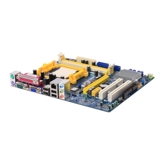
Page 11: Layout
1-2 layout 1. 4-pin ATX 12V Power Connector 13. Floppy Connector 2. Chassis Intrusion Alarm Header 14. Front Panel Connector 3. USBPWR2 Jumper 15. USBPWR1 Jumper 4. System fan Header 16. Front USB Connectors 5. Clear CMOS Jumper 17. SATA Connectors 6. -
Page 12: Back Panel Connectors
1-3 back Panel Connectors PS/2 Mouse Port Parallel Port LAN Port Line In Line Out Microphone PS/2 Keyboard Port Serial Port VGA Port USB Ports Audio Ports 1. PS/2 Mouse Port Use the upper port (green) to connect a PS/2 mouse. 2. - Page 13 No Link No Link 100M Green Data Activity Orange 10/100Mb/s Connection Blinking No Link No Link 10Mb/s Connection 1000M Green Data Activity Green 100Mb/s Connection Blinking Orange 1000Mb/s Connection Active Link M61PMV and M61PMV-E support 10/100Mb/s Ethernet. M61PMVK supports 1Gb/s Ethernet.
- Page 14 This chapter introduces the hardware installation process, including the installation of the CPU, memory, power supply, slots, pin headers and the mounting of jumpers. Caution should be exercised during the installation of these modules. Please refer to the motherboard layout prior to any installation and read the contents in this chapter carefully.
-
Page 15: Install The Cpu And Cpu Cooler
2-1 Install the CPU and CPU Cooler Read the following guidelines before you begin to install the CPU : ■ Make sure that the motherboard supports the CPU. ■ Always turn off the computer and unplug the power cord from the power supply before installing the CPU to prevent hardware damage. -
Page 16: Install The Cpu Cooler
CPU socket lever back to its locked position. Install the CPU Cooler Follow the steps below to correctly install the CPU cooler. (The following procedures use Foxconn cooler as the example.) 2. Buckle the heatsink firmly at one 1. -
Page 17: Install The Memory
2-2 Install the Memory Read the following guidelines before you begin to install the memory : ■ Make sure that the motherboard supports the memory. It is recommended that memory of the same capacity, brand, speed, and chips be used. ■... -
Page 18: Installing A Memory
Installing a Memory Before installing a memory module, make sure to turn off the computer and unplug the power cord from the power outlet to prevent damage to the memory module. Be sure to install DDR2 DIMMs on this motherboard. Notch If you take a look at front side of memory module, it has asymmetric pin counts on both sides separated by a notch in the middle, so it can only fit in one direction. -
Page 19: Install An Expansion Card
2-3 Install an expansion Card ■ Make sure the motherboard supports the expansion card. Carefully read the manual that came with your expansion card. ■ Always turn off the computer and unplug the power cord from the power outlet before installing an expansion card to prevent hardware damage. -
Page 20: Install Other Internal Connectors
2-4 Install other Internal Connectors Power Connectors This motherboard uses an ATX power supply. In order not to damage any device, make sure all the devices have been installed properly before applying the power supply. 24-pin ATX power connector : PWR1 PWR1 is the ATX power supply connector. - Page 21 front Panel Connector : fP1 This motherboard includes one connector for connecting the front panel switch and LED Indicators. HDD-LED PWR-LED Hard Disk leD Connector (HDD-leD) RESET-SW PWR-SW Connect to the chassis front panel IDE indicator LED. It EMPTY indicates the active status of the hard disks. This 2-pin connector is directional with +/- sign.
- Page 22 PORT1_L AUD_GND Audio Connector : f_AUDIo PORT1_R PRESENCE_J PORT2_R SENSE1_RETURN The audio connector supports HD Audio standard. SENSE_SEND EMPTY It provides the Front Audio output choice. PORT2_L SENSE2_RETURN F_AUDIO Audio Connector : CD_IN CD_L GND CD_R CD_IN is a Sony standard audio connector, it can be con- nected to a CD/DVD-ROM drive through a CD/DVD audio cable.
-
Page 23: Jumpers
2-5 Jumpers For some features needed, users can change the jumper settings on this motherboard to modify them. This section explains how to use the various functions of this motherboard by changing the jumper settings. Users should read the following content carefully prior to modifying any jumper setting. Description of Jumpers 1. - Page 24 USB device wake-up Jumpers: USB_PWR1 / USB_PWR2 1. Set the jumper to pins 1-2 (+5V) to wake up the computer from S1 sleep mode using the connected USB devices. 2. Set the jumper to pins 2-3 (+5VSB) to wake up the computer from S3 and S4 sleep modes using the connected USB devices.
- Page 25 This chapter tells how to change system settings through the BIOS Setup menus. Detailed descriptions of the BIOS parameters are also provided. You have to run the Setup Program when the following cases occur : 1. An error message appears on the screen during the system Power On Self Test (POST) process.
-
Page 26: Enter Bios Setup
enter bIoS Setup The BIOS is the communication bridge between hardware and software, correctly setting up the BIOS parameters is critical to maintain optimal system performance. Power on the computer, when the message "Press [Del] to enter Setup, [eSC] to boot menu" appears at the bottom of the screen, you can press [Del] key to enter Setup. - Page 27 ► Power Management Setup All the items related with Green function features can be set up through this menu. ► PC Health Status This setup enables you to read/change Fan speeds, and displays temperatures and voltages of your CPU/System. ► Load Optimized Defaults The optimal performance settings can be loaded through this menu.
-
Page 28: System Information
[ None ] ► SATA Channel 4 Master [1.44M, 3.5 in.] Drive A Halt On [All , But Keyboard] Model Name M61PMV BIOS Version 1024M Memory MAC Address 04 4B 80 80 80 03 AMD Athlon(tm) 64 X2 Dual Core Processor 5200+ ↑↓→←:Move Enter:Select... - Page 29 ► SATA Channel 1/2/3/4 Master When SATA Operation Mode is set to [IDE], These items will appear. The relationships between SATA channels and SATA ports on the motherboard are : SATA Channel 1 Master is the SATA port 1 of the motherboard. SATA Channel 2 Master is the SATA port 2.
-
Page 30: Fox Central Control Unit
fox Central Control Unit Phoenix - AwardBIOS CMOS Setup Utility Fox Central Control Unit ► Smart BIOS [Press Enter] Press Enter Item Help ► Fox Intelligent Overclock [Press Enter] ► Memory Timing Setting [Press Enter] Menu Level ► Memory Voltage [Default] K8<->NB HT Speed [Auto]... -
Page 31: Smart Bios
[Auto] : Enable entire cores, [Single Core] : Enable 1 core, [Dual Core] : Enable 2 cores, [Tri Core] : Enable 3 cores, [Quad Core] : Enable 4 cores. ► Super BIOS Protect To protect the system BIOS from virus attack, there is a BIOS write-protection mechanism provided. -
Page 32: Memory Timing Setting
Fox Intelligent Overclock Phoenix - AwardBIOS CMOS Setup Utility Fox Intelligent Overclock CPU Clock [200] Item Help PCIE Clock [100] NPT FID Control [Auto] Menu Level ► ↑↓→←:Move Enter:Select +/-/PU/PD:Value F10:Save ESC:Exit F1:General Help F5: Previous Values F7: Optimized Defaults ►... - Page 33 ► DCTs Mode (Appears only when CPU support) DCT stands for DRAM Controller. Ganged refers to the use of both DRAM controllers within a memory controller acting in con- cert to access memory. For a description of ganged (128-bit DRAM data width) and unganged (64-bit DRAM data width) DRAM modes : Ganged channels (DDR2) : ■...
-
Page 34: Advanced Bios Features
Advanced BIOS Features Phoenix - AwardBIOS CMOS Setup Utility Advanced BIOS Features ► Removable Device Priority [Press Enter] Item Help Press Enter ► Hard Disk Boot Priority [Press Enter] First Boot Device [Hard Disk] Menu Level ► Second Boot Device [CDROM] Select removable boot Third Boot Device... -
Page 35: Advanced Chipset Features
Advanced Chipset Features Phoenix - AwardBIOS CMOS Setup Utility Advanced Chipset Features Frame Buffer Size [128M] 128M Item Help Menu Level ► ↑↓→←:Move Enter:Select +/-/PU/PD:Value F10:Save ESC:Exit F1:General Help F5: Previous Values F7: Optimized Defaults ► Frame Buffer Size Allocates system memory for use as video memory to ensure the most efficient use of available resources for maximum 2D/3D graphics performance. -
Page 36: Integrated Peripherals
Integrated Peripherals Phoenix - AwardBIOS CMOS Setup Utility Integrated Peripherals ► OnChip IDE Devices [Press Enter] Press Enter Item Help ► RAID Config [Press Enter] ► OnBoard Devices [Press Enter] Menu Level ► ► SuperIO Devices [Press Enter] ► USB Devices [Press Enter] ↑↓→←:Move Enter:Select +/-/PU/PD:Value... -
Page 37: Raid Config
RAID Config Phoenix - AwardBIOS CMOS Setup Utility RAID Config RAID Enable IDE] Item Help Disabled x SATA Pri-Master RAID Disabled x SATA Pri-Slave RAID Disabled Menu Level ► x SATA Sec-Master RAID Disabled x SATA Sec-Slave RAID Disabled ↑↓→←:Move Enter:Select +/-/PU/PD:Value F10:Save ESC:Exit F1:General Help F5: Previous Values... -
Page 38: Onboard Devices
OnBoard Devices Phoenix - AwardBIOS CMOS Setup Utility OnBoard Devices OnBoard Audio Controller Item Help Auto OnBoard LAN Controller [Auto] OnBoard LAN Boot ROM [Disabled] Menu Level ► ↑↓→←:Move Enter:Select +/-/PU/PD:Value F10:Save ESC:Exit F1:General Help F5: Previous Values F7: Optimized Defaults ►... - Page 39 SuperIO Devices Phoenix - AwardBIOS CMOS Setup Utility SuperIO Devices OnBoard FDC Controller [Enabled] Item Help Enabled OnBoard Serial Port 1 [3F8/IRQ4] OnBoard Serial Port 2 [2F8/IRQ3] Menu Level ► Serial Port 2 Mode Select [Normal] x IrDA Duplex Mode Half OnBoard Parallel Port [378/IRQ7]...
- Page 40 USB Devices Phoenix - AwardBIOS CMOS Setup Utility USB Devices OnChip USB Item Help V1.1+V2.0 USB Keyboard Support [Enabled] USB Mouse Support [Disabled] Menu Level ► USB Storage Support [Enabled] ↑↓→←:Move Enter:Select +/-/PU/PD:Value F10:Save ESC:Exit F1:General Help F5: Previous Values F7: Optimized Defaults ►...
-
Page 41: Power Management Setup
Power Management Setup Phoenix - AwardBIOS CMOS Setup Utility Power Management Setup ACPI Function [Enabled] Enabled Item Help ACPI Suspend Type [S3(STR)] Power Button [Instant-Off] Menu Level ► ** Power Management Events ** Wake Up by PCI/PCIE PME [Disabled] USB Resume from S3 [Disabled] Resume by Alarm [Disabled]... - Page 42 ► ACPI Function This item is used to enable or disable the ACPI function. ► ACPI Suspend Type This item is used to set the energy saving mode of the ACPI function. When you select “S1 (POS)” mode, the power is always on and computer can be resumed at any time. When you select “S3 (STR)”...
- Page 43 and [Keyboard 98]. ► Hot Key Resume Wen "PS/2 KB Resume from S3" is set to [Hot KEY], this item allows you to press a [Ctrl] + Function key to wake up the system from S3 mode.
-
Page 44: Pc Health Status
PC Health Status Phoenix - AwardBIOS CMOS Setup Utility PC Health Status Case Open Warning [Disabled] Disabled Item Help Shutdown Temperature [Disabled] CPU Vcore 1.34 V Menu Level ► VTT(V) 1.88 V +3.3V 3.34 V + 5V 5.16 V + 12V 11.90 V 5VSB(V) 4.99V... -
Page 45: Load Optimized Defaults
Load Optimized Defaults Select this option and press [Enter]. A dialogue pops out, input [Y] then press [Enter] to load the defaults; press [N] to skip. Load Optimized Defaults (Y/N)? N By this default, BIOS have set the optimized performance parameters of system to improve the performances of system components. - Page 46 The utility CD that came with the motherboard contains useful software and several utility drivers that enhance the motherboard features. This chapter includes the following information: ■ Utility CD content ■ Install driver and utility ■ FOX ONE ■ FOX LiveUpdate ■...
-
Page 47: Utility Cd Content
M61PMV-E: A. NVIDIA MCP61 Chipset Driver B. Realtek HDA Audio Driver C. Realtek LAN Driver M61PMV/ M61PMVK: A. NVIDIA MCP61 Chipset Driver B. VIA HDA Audio Driver 2. Software Utilities Use these options to install additional software programs. FOX ONE is a very powerful user interface program which allows you to change your system setting without going to BIOS. -
Page 48: Install Driver And Utility
Install driver and utility 1. Install Driver M61PMV-e: You must click "NVIDIA MCP61 Chipset Driver" to install it first. After that, you can click "One Click Setup" to install all the other drivers left, or you can click on each individual driver to install it manually. -
Page 49: Install Utility
2. Install Utility You can select the specific utility to install. -
Page 50: Fox One
foX oNe FOX ONE is a powerful utility for easily modifying system settings. It also allows users to monitor various temperature values, voltage values, frequencies and fan speeds at any time. With FOX ONE, you can : ■ Modify system performance settings, such as the CPU and memory bus speeds, CPU voltages, fan speeds, and other system performance options. -
Page 51: Main Page
1. Main Page Show CPU Toolbar Information Alert Lamp Switch Button Skin Button Exit Minimum Configuration Homepage Monitor Frequency/Voltage/Fan speed/Temperature value Toolbar Use the toolbar to navigate to other pages. Alert lamp When the system is in healthy state, the color of alert lamp is green. When the system is in abnormal state, the alert lamp color is red. - Page 52 Click this button to exit the program. Minimum Click this button to drop the FOX ONE to Windows system tray located at the lower right corner of your screen. Homepage Click this button to visit Foxconn motherboard website : http://www.foxconnchannel.com...
- Page 53 Configuration This menu allows you to configure : 1). Monitor interval (ms) : This is to define the interval of different messages of system settings which are to be displayed on Simple Mode screen. Minimum value is 1 second. 2). Simple Mode : To select which message of system settings are to be displayed in the Simple Mode.
- Page 54 Step 1 : Click Calibration icon, a message pops out to ask for continue. Select Yes. Step 2 : After data is collected, it will ask you to restart your computer now. Later on, when the FOX ONE program is activated, and F.I.S. feature (in CPU Page) is also enabled, FOX ONE will automatically adjust your CPU clock according to your system loadings.
-
Page 55: Cpu Control
2. CPU Page - CPU Control This page lets you select (or overclock) CPU clock to meet the current performance level of the system. The fastest and suitable CPU clock running for current system can be calculated by FOX ONE automatically or manually input by yourselves. Manual : You can press the up/down button to adjust your CPU clock. - Page 56 You can see the system is raising CPU clock until the system hangs. Push RESET button on the front panel of your system to restart the computer. Run FOX ONE program again, it will inform you the previous test found that 255MHz is the recommended CPU clock for your system.
-
Page 57: Frequency Control
FOX Intelligent Stepping (F.I.S., Optional) Select FOX Intelligent Stepping will allow your system to automatically adjust your CPU clock rate based on different system loadings. For example, if you select Power Gaming, CPU clock will be driven to run at its maximum speed. While in Energy Saving, CPU will lower down its speed to a minimum. -
Page 58: Limit Setting
4. Limit Setting 4.1 Limit Setting - CPU Temperature This page lets you to set CPU high limit temperature and enable the alert function. Go to Limit Setting Show current CPU page temperature value Enable alert function when the CPU temperature is higher than high limit value Show current high... - Page 59 4.3 Limit Setting - CPU Fan This page lets you to set CPU fan low limit rpm and enable the alert function. Show current CPU fan rpm value Enable alert function when the CPU fan runs slower than the low limit rpm value Show current low limit rpm value of CPU fan...
-
Page 60: Voltage Control
4.5 Limit Setting - FAN1 Fan This page lets you to set FAN1 fan low limit rpm and enable the alert function. Show current FAN1 fan rpm value Enable alert function when the FAN1 fan runs slower than low limit rpm value Show current low limit rpm value of FAN1 fan Set low limit rpm by... -
Page 61: Fan Control
6. Fan Page - Fan Control This page lets you enable Smart Fan function or set the fan speed by manual. When Smart Fan is selected, you must use a 4-pin CPU cooler in your system. Go to Fan page Enable or disable smart fan function Set fan speed by... -
Page 62: Fox Liveupdate
FOX LiveUpdate FOX LiveUpdate is a useful utility to backup and update your system BIOS, drivers and utilities by local or online. Supporting Operating Systems : ■ Windows 2000 ■ Windows XP (32-bit and 64-bit) ■ Windows 2003 (32-bit and 64-bit) ■... - Page 63 1-2 local Update - backup This page can backup your system BIOS. You can click “Backup”, and key in a file name, then click “Save” to finish the backup operation. The extension of this backup file is ".BIN" for Award BIOS and ".ROM"...
-
Page 64: Online Update
2. online Update 2-1 online Update - Update bIoS This page lets you update your system BIOS from Internet. Click “start”, it will search the new BIOS from Internet. Then follow the wizard to finish the update operation. Click here Current information Search new BIOS from Internet... - Page 65 Select the driver to update Browse detailed information Install the selected driver Close the window 2-3 online Update - Update Utility This page lets you update utilities from Internet. Click “start”, it will search the new utilities from Internet. Then follow the wizard to finish the update operation. Click here Current information Search new utilities...
- Page 66 2-4 online Update - Update All This page lets you update your system drivers from Internet. Click “start”, it will search all new BIOS/drivers/utilities from Internet. Then follow the wizard to finish the update operation. Click here Current information Search all new BIOS/ drivers/utilities from Internet Browse detailed...
-
Page 67: Configure
3. Configure 3-1 Configure - option This page lets you set auto search options. After you enable the auto search function, FOX LiveUpdate will start its searching from Internet and if any qualified item found, it will pop out a message on the task bar to inform you to do the next step. - Page 68 When you enable "Auto Search FOX LiveUpdate", if your FOX LiveUpdate version is older, it will auto search from internet and prompt you to install the new version. Prompt you to install the new FOX LiveUpdate 3-2 Configure - System This page lets you set the backup BIOS location and change different skin of the FOX LiveUpdate utility.
-
Page 69: About & Help
3-3 Configure - Advance This page lets you select to flash BIOS / Boot Block and clear CMOS. If you choose Flash Boot Block, it means BIOS is not protective, and you must make sure the flash process is continuous and without any interruption. -
Page 70: Fox Logo
foX loGo FOX LOGO is a simple and useful utility to backup, change and delete the boot time Logo. The boot Logo is the image that appears on screen during POST (Power-On Self-Test). You can prepare a JPG image (1024x768) file, then use FOX LOGO to open it and change the boot time Logo. -
Page 71: Fox Dmi
foX DMI FOX DMI is a full Desktop Management Interface viewer, and it provides three DMI data formats : Report, Data Fields and Memory Dump. With DMI information, system maker can easily analyze and troubleshoot your motherboard if there is any problem occurred. Supporting Operating Systems : ■... -
Page 72: Chapter 5 Raid Configuration
This chapter will cover two topics : ■ Creating a Bootable Array - Installing a new Windows XP (Vista) in a brand new RAID system. ■ Creating a Non-Bootable Array - Existing Windows XP (Vista) system with new RAID built as data storage. It includes the following information : ■... -
Page 73: Creating A Non-Bootable Array - Existing Windows Xp (Or Vista)
Creating a Bootable Array - Installing a new Windows XP (or Vista) in a brand new RAID system. 1. Follow 5-1 to create two RAID driver diskettes. 2. Follow 5-2 to set RAID enabled in BIOS. 3. Follow 5-3 to select a RAID array for use. 4. -
Page 74: Raid Configuration Introduction
RAID Configuration Introduction RAID (Redundant Array of Independent Disks) is a method for computer data storage schemes that divide and/or replicate data among multiple hard drives. RAID can be designed to provide increased data reliability (fault tolerance) or increased I/O (input/ output) performance, or both. - Page 75 RAID 0 (Striping) RAID 0 reads and writes sectors of data interleaved among multiple drives. If any disk member fails, it affects the entire array. The disk array data capacity is equal to the number of drive members times the capacity of the smallest member. RAID 0 does not support fault tolerance.
-
Page 76: Nvidia® Mediashield Driver
NVIDIA MediaShield Driver ® The NVIDIA MediaShield driver supports RAID 0, RAID 1, RAID 5, and RAID 0+1 ® functions. It allows you to get high performance with fault tolerance, big capacity, or data safety provided by different RAID functions. Here, we will use four SATA hard disks as an example to guide you how to select your RAID system. - Page 77 MediaShield Utillity Apr 26 2007 - Define a New Array - Optimal RAID Mode: Mirrored Striping Stripe Block: Optimal Free Disks Array Disks Port Disk Model Capacity Port Disk Model Capacity 0.0 WDC WD1200JD-9 111.79GB 1.0 WDC WD1200JD-9 111.79GB 1.1 Hitachi HDT725 232.88GB [-›] Add 2.0 HDS728080PLA38 76.69GB...
-
Page 78: Create Two Raid Driver Diskettes
5-1 Create two RAID Driver Diskettes If you want to install a brand new Windows XP on a RAID system, you need to create two RAID driver floppy diskettes which will be used during Windows XP installation later. 1. Find a PC, put a diskette into its floppy drive A:, this diskette will be formatted later. - Page 79 6. You can input a volume label for this diskette, click on "Start" to format. 7. Click on "OK" to go through this warning message. 8. Format finished. Click "OK", then click "Close" to continue copying of RAID driver into this diskette.
-
Page 80: Raid Enable In Bios
5-2 RAID enable in bIoS 1. Enter the BIOS setup by pressing [DEL] key when boot up. 2. Select the “Integrated Peripherals” from the “Main menu”, then select the “RAID Config” menu and press [Enter] to go to the configuration items. 3. - Page 81 Create RAID 0 (Striping) 1. Select "Striping" from the RAID Mode. The menu appears : MediaShield Utillity Apr 26 2007 - Define a New Array - Optimal RAID Mode: Mirrored Striping Stripe Block: Optimal Free Disks Array Disks Port Disk Model Capacity Port Disk Model Capacity...
- Page 82 4. The stripe value should be selected based on different applications. It ranges from 4KB to 128KB. Some suggested choices are : 16K - Best for sequential transfer. 64K - Good general purpose strip size. 128K - Best performance for most desktops and workstations. Keep it at Optimal default value.
- Page 83 6. In above screen, you also can press [Enter] to know the detailed drive information of this RAID system. Press [D] here allow you to delete previous settings, and go back to the first time when MediaShield was started. Array 4 : NVIDIA STRIPE 153.38G - Array Detail - RAID Mode: Striping Striping Width :...
- Page 84 Create RAID 1 (Mirroring) 1. Select “Mirroring” from the RAID Mode. MediaShield Utillity Apr 26 2007 - Define a New Array - Optimal RAID Mode: Mirrored Stripe Block: Optimal Mirroring Free Disks Array Disks Port Disk Model Capacity Port Disk Model Capacity 0.0 WDC WD1200JD-9 111.79GB 1.0 WDC WD1200JD-9 111.79GB...
-
Page 85: If You Want To Build A New Operating System (Such As Windows Xp) In This Raid
4. The stripe block value is fixed and not changeable. Press [F7] to finish the setting.Press [Y] to clear disk data. MediaShield Utility Apr 26 2007 - Define a New Array - Optimal Mirroring RAID Mode: Mirrored Stripe Block: Optimal Free Disks Array Disks Port Disk Model... - Page 86 6. In above screen, you also can press [Enter] to know the detailed drive information of this RAID system. Press [D] here allow you to delete previous settings, and go back to the first time when MediaShield was started. Array 4 : NVIDIA MIRROR 232.88G - Array Detail - RAID Mode: Mirroring Stripe Width :...
- Page 87 Create RAID 0+1 (Stripe Mirroring) 1. Select “Stripe Mirroring” from the RAID Mode. The menu appears : MediaShield Utillity Apr 26 2007 - Define a New Array - Optimal RAID Mode: Mirrored Stripe Block: Optimal Stripe Mirroring Free Disks Array Disks Port Disk Model Capacity Port Disk Model...
- Page 88 4. The stripe value should be selected based on different applications. It ranges from 4KB to 128KB. Some suggested choices are : 16K - Best for sequential transfer. 64K - Good general purpose strip size. 128K - Best performance for most desktops and workstations. Keep it at Optimal default value.
- Page 89 6. In above screen, you also can press [Enter] to know the detailed drive information of this RAID system. Press [D] here allow you to delete previous settings, and go back to the first time when MediaShield was started. Array 4 : NVIDIA RAID 0+1 153.38G - Array Detail - RAID Mode: Striped Mirror Stripe Width :...
-
Page 90: Create Raid
Create RAID 5 1. Select “RAID5” from the RAID Mode. The menu appears : MediaShield Utillity Apr 26 2007 - Define a New Array - Optimal RAID Mode: Mirrored RAID 5 Stripe Block: Optimal Free Disks Array Disks Port Disk Model Capacity Port Disk Model Capacity... - Page 91 4. The stripe value should be selected based on different applications. It ranges from 4KB to 128KB. Some suggested choices are : 16K - Best for sequential transfer. 64K - Good general purpose strip size. 128K - Best performance for most desktops and workstations. Keep it at Optimal default value.
- Page 92 6. In above screen, you also can press [Enter] to know the detailed drive information of this RAID system. Press [D] here allow you to delete previous settings, and go back to the first time when MediaShield was started. Array 4 : NVIDIA RAID5 153.38G - Array Detail - RAID Mode: RAID5 Stripe Width :...
- Page 93 Create Spanning RAID 1. Select “Spanning” from the RAID Mode. The menu appears : MediaShield Utillity Apr 26 2007 - Define a New Array - Optimal RAID Mode: Mirrored Stripe Block: Optimal Spanning Free Disks Array Disks Port Disk Model Capacity Port Disk Model Capacity...
- Page 94 4. The stripe block value is fixed and not changeable. Press [F7] to finish the setting. Press [Y] to clear disk data. MediaShield Utillity Apr 26 2007 - Define a New Array - Optimal RAID Mode: Mirrored Stripe Block: Optimal Spanning Free Disks Array Disks...
- Page 95 6. In above screen, you also can press [Enter] to know the detailed drive information of this RAID system. Press [D] here allow you to delete previous settings, and go back to the first time when MediaShield was started. Array 4 : NVIDIA JBOD 421.36G - Array Detail - RAID Mode: Spanning Stripe Width :...
-
Page 96: Install A New Windows Xp
Creating a Bootable Array- Install a New Windows XP Assume a Mirrored array (232.88GB) was created as introduced in section 5-3, after the system restarts : 1. Press [DEL] to enter BIOS Setup during POST. 2. Insert the Windows installation CD into the optical drive. 3. - Page 97 5. After some files are copied to your system, the following picture appears, press [S] to continue the specific driver installation. Windows Setup Setup could not determine the type of one or more mass storage devices installed in your system, or you have chosen to manually specify an adapter. Currently, Setup will load support for the following mass storage device(s): <none>...
- Page 98 7. There are two drivers, all these two drivers must be installed. Press [Enter] to select the first driver - "NVIDIA RAID Driver (required)". Windows Setup You have chosen to configure a SCSI Adapter for use with Windows, using a device support disk provided by an adapter manufacturer. Select the SCSI Adapter you want from the following list, or press ESC to return to the previous screen.
- Page 99 9. Use [↓] key to select "NVIDIA nForce Storage Controller (required)", then press [Enter]. Still, The RAID floppy diskette 1 is inside the floppy drive. Windows Setup You have chosen to configure a SCSI Adapter for use with Windows, using a device support disk provided by an adapter manufacturer. Select the SCSI Adapter you want from the following list, or press ESC to return to the previous screen.
- Page 100 11. Windows will display the partition of your system. As we are using a Mirrored RAID array as an example, its size 232.88GB is now displayed as 238473MB. You can press [C] to create partitions as many as you wish, assign them C:, D: or E: logical drive names.
- Page 101 13. The Windows XP install processes will ask you to format your hard disk, select quick formatting using NTFS file system, press [ENTER]. Windows XP Professional Setup The partition you selected is not formatted. Setup will now format the partition. Use the UP and DOWN ARROW keys to select the file system you want, and then press ENTER.
- Page 102 15. After Setup copies files from RAID floppy diskette 2 to the Windows installation folders, it then will ask you to insert the first RAID diskette into floppy drive again. Press [Enter] to continue when it is done. Windows Setup Insert the disk labeled : NVIDIA RAID DRIVER (SCSI) disk 1 into drive A:...
-
Page 103: Setting Up A Non-Bootable Raid Array
5-5 Setting Up a Non-Bootable RAID Array This section assumes the following setup : ■ Boot Disk with Windows XP installed : One hard disk HDS728080PLAT20 (80GB) is connected to the IDE channel, and set to Master. ■ A Mirrored RAID Array Disk : Two SATA hard disks are configured as a mirrored RAID1 array, they are : Hitachi HDT725025VLA, (232.88GB) connected to SATA port2 of the motherboard. - Page 104 2. Select a RAID array for use (also can refer to section 5-3) After rebooting your computer, you will see the RAID software prompting you to press [F10]. Press [F10] to enter the NVIDIA MediaShield BIOS setup and configure the mirrored RAID array as described in the 5-3 section.
- Page 105 5. The installation of driver may take a while, after the NVIDIA driver is installed, it will ask you to click "Finish" to restart your computer. 6. When Windows starts, a "Found New Hardware Wizard" appears. Click on "Cancel" to ignore it.
- Page 106 7. After PC starts, the RAID array is now ready to be initialized under Windows. Launch Computer Management by clicking Start -> Settings -> Control Panel then open the Administrative Tools folder and double click on Computer Management. Click Disk Management (under the Storage section). The Initialize and Convert Disk Wizards appears.
- Page 107 11. The Computer Management window appears. The actual disks listed will depend on your system. In below figure, you can see there is a 232.88 GB unallocated partition. You must format the unallocated disk space before using it. Right click "Unallocated space", select "New Partition…" and follow the Wizard instructions.
- Page 108 17. The format of disk array (Disk1) is in processing. 18. Format completed, now you can start using your RAID array.