
Related Manuals for Honeywell FUSION III DVR


Summary of Contents for Honeywell FUSION III DVR
- Page 1 FUSION III DVR Digital Recording and Transmission System User Guide Document 900.0803 – 08/16 – Rev 2...
- Page 2 ISSUE DATE REVISIONS June 2006 Initial Release August 2006 Updated for content...
- Page 3 USERS OF THE PRODUCT ARE RESPONSIBLE FOR CHECKING AND COMPLYING WITH ALL FEDERAL, STATE, AND LOCAL LAWS AND STATUTES CONCERNING THE MONITORING AND RECORDING OF VIDEO AND AUDIO SIGNALS. HONEYWELL VIDEO SYSTEMS SHALL NOT BE HELD RESPONSIBLE FOR THE USE OF THIS PRODUCT IN VIOLATION OF CURRENT LAWS...
- Page 4 NATIONAL POWER DEVIATION STANDARDS AUSTRALIA / NEW ZEALAND COMPONENTS COMPLY WITH THE RELEVANT PORTIONS OF IEC 60950 OR THE APPLICABLE COMPONENT STANDARD OR THE RELEVANT AUSTRALIAN / NEW ZEALAND STANDARD. AC POWER DISTRIBUTION SYSTEMS CLASSIFIED AS TT OR IT ARE NOT ALLOWED INTENDED FOR USE ON A TN SYSTEM.
- Page 5 GERMANY (GESETZ UBER TECHNISCHE ARBEITSMITTEL (GARATESICHERHEITSGESETZ) [LAW OF TECHNICAL LABOUR EQUIPMENT {EQUIPMENT SAFETY LAW}], OF 23RD OCTOBER 1992, ARTICLE 3, 3RD PARAGRAPH, 2ND SENTENCE, TOGETHER WITH THE "ALLGEMEINE VERWALTUNGSVORSCHRIFT ZUR URCHFUHRUNG DES ZWEITEN ABSCHRITTS DES GERATESICHERHEITSGESETZES" [GENERAL ADMINISTRATIVE REGULATION ON THE EXECUTION OF THE SECOND SECTION OF THE EQUIPMENT SAFETY LAW], OF 10TH JANUARY 1996, ARTICLE 2, THE PARAGRAPH, ITEM 2).
-
Page 6: Rack Mount Instructions
RACK MOUNT INSTRUCTIONS A) Elevated Operating Ambient – If installed in a closed or multi-unit rack assembly, the operating ambient temperature of the rack environment may be greater than room ambient. Therefore, consideration should be given to installing the equipment in an environment compatible with the maximum ambient temperature (Tma) specified by the manufacturer. - Page 7 EN 50130-4:1996 Notice 1. Uninterrupted Power supply (UPS) 2. Maximum lengths of wiring connected to the sensor inputs and control outputs are 30 meters. EN 55022 CLASS A Notice WARNING This is a class A product. In a domestic environment this product may cause radio interference in which case the user may be required to take adequate measures.
- Page 8 OPTICAL AND ACOUSTICAL STATEMENTS VISIBLE LED STATEMENT The LEDs on this DVR unit are classified as “Class 1 LED Product” in accordance with EN 60825-1. LASER SAFETY STATEMENT FOR A CLASS 1 LASER PRODUCT This CD-ROM Storage device has been tested and found to comply with the limits for a Class B digital device, pursuant to Part 15 of the FCC Rules.
- Page 9 Object and Liquid Entry Points – Never insert foreign objects into the DVR unit, other than the media types approved by Honeywell, as they may touch dangerous voltage points or short-out parts that could result in a fire or electrical shock. Never spill liquid of any kind on the product.
- Page 10 Damage Requiring Service – Unplug the unit from the outlet and refer servicing to qualified service personnel under the following conditions: a. When the power-supply cord or plug is damaged. b. If liquid has been spilled, or objects have fallen into the unit. c.
-
Page 11: Notes On Maintenance
NOTES ON CLEANING • Use a soft dry cloth for cleaning. • For stubborn dirt, soak the cloth in a weak detergent solution, wring well and wipe. Use a dry cloth to wipe it dry. Do not use any type of solvent, such as thinner and benzene, as they may damage the surface of the DVR unit. - Page 12 WARNING TO REDUCE THE RISK OF ELECTRICAL SHOCK, DO NOT EXPOSE THIS APPLIANCE TO RAIN OR MOISTURE. DANGEROUS HIGH VOLTAGES ARE PRESENT INSIDE THE ENCLOSURE. DO NOT OPEN THE CABINET. REFER SERVICING TO QUALIFIED PERSONNEL ONLY. CAUTION C A U T I O N RISK OF ELECTRIC SHOCK DO NOT OPEN CAUTION: TO REDUCE THE RISK OF ELECTRIC SHOCK,...
-
Page 15: Table Of Contents
TABLE OF CONTENTS SECTION 1 INTRODUCTION ..................1–1 PRODUCT DESCRIPTION ......................1–1 FEATURES..........................1–2 SECTION 2 CONTROLS AND CONNECTIONS ............2–1 BASIC FEATURES........................2–1 FRONT PANEL CONTROLS AND LEDS .................. 2–2 REAR PANEL CONNECTORS ....................2–3 SECTION 3 GETTING STARTED................3–1 IDENTIFYING INCLUDED COMPONENTS ................ - Page 16 AUDIO RECORDING ......................5–11 5.4.5 FRAME SETUP ........................5–12 FRAME SETUP (HIGH-END) ....................5–12 5.5.1 FRAME SETUP (LOW-END) ....................5–14 5.5.2 RECORDING SCHEDULE ....................... 5–16 DAY OF THE WEEK ......................5–18 5.6.1 CREATING A SIMPLE SCHEDULE (BY EXAMPLE) ............5–18 5.6.2 SCHEDULING SENSORS AND RELAYS (BY EXAMPLE) ..........
- Page 17 PTZ ADDRESS SETTING......................7–14 ACTIVATING THE PTZ STATUS ON CLOSE OPTION ............7–14 7.8.1 ACCESSING PTZ Menus......................7–15 OPENING AND EDITING THE HONEYWELL KD6 MENU ..........7–15 7.9.1 7.10 USING THE ON-SCREEN CONTROLLER AND COMPASS ..........7–16 THE PTZ CONTROLLER ..................... 7–17 7.10.1...
- Page 18 11.3 LOADING VIDE0 FROM CD-ROM OR HARD DRIVE............. 11–3 SECTION 12 ALARM MONITOR................12–1 12.1 ALARM MONITOR OVERVIEW....................12–1 12.2 INSTALLING THE ALARM MONITOR ..................12–1 12.3 CONFIGURING THE DVR ....................... 12–2 12.4 CONFIGURING THE CLIENT PC .................... 12–3 12.5 ALARM MONITOR WINDOW ....................
-
Page 21: Section 1 Introduction
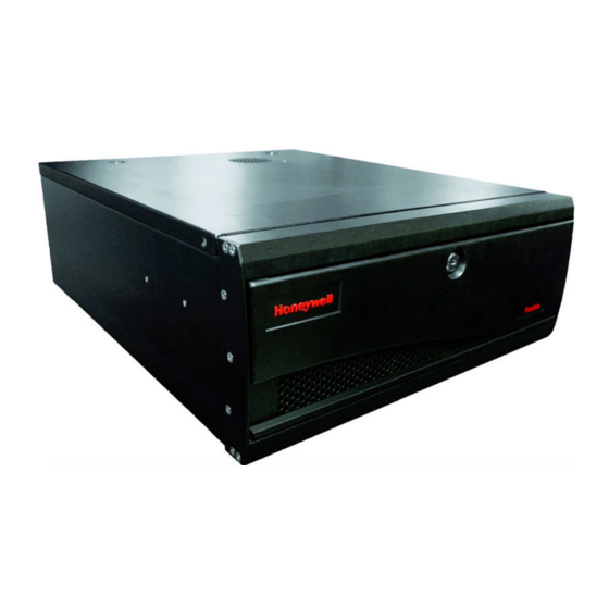
INTRODUCTION PRODUCT DESCRIPTION The Honeywell Fusion DVR is simply a server that performs as a High Definition Digital Recorder. By utilizing the many features of a computer, including processing power, storage capacity, graphics compression, and security features, the DVR unit is more powerful than the analog recorders of the past. -
Page 22: Features
FUSION III DVR Digital Recording and Transmission System FEATURES Honeywell’s Fusion DVRs include the following features: • Optimized and Designed for Microsoft® Windows XP® Embedded • Supports up to 16 Digital Control Outputs on Alarm Activation • Supports up to 16 Alarm Inputs for Alarm Control •... -
Page 23: Section 2 Controls And Connections
CONTROLS AND CONNECTIONS BASIC FEATURES Honeywell’s state-of-the-art High Definition Digital Recorders are housed in a high performance and versatile 4U Aluminum Rack-Mount case allowing easy storage of multiple DVRs for enterprise applications. Every Fusion DVR Unit comes equipped with the latest technology. -
Page 24: Front Panel Controls And Leds
FUSION III DVR Digital Recording and Transmission System FRONT PANEL CONTROLS AND LEDS The front panel of the DVR unit contains the devices that will be commonly used for data removal, retrieval, and backup replacement. The most common components and buttons are shown below. -
Page 25: Rear Panel Connectors
CONTROLS AND CONNECTIONS REAR PANEL CONNECTORS The rear panel of the DVR unit contains virtually all of the connectors you will be using. Below is a diagram that outlines the location and description of each connector: 32 Channel Capture card layout and tyoe may vary depending on 32 channel configuration. - Page 26 FUSION III DVR Digital Recording and Transmission System 8/16 Channel 1 to 2 of the 4 channel audio input cards may be mounted in any of the 4 end PCI slots CH 1 in CH 2 in CH 3 in...
-
Page 27: Section 3 Getting Started
GETTING STARTED IDENTIFYING INCLUDED COMPONENTS Honeywell’s Fusion DVRs come with a mouse, keyboard and selected software and cables. Identify the following components to make sure everything has been properly included with your new DVR unit. If any of the following items are missing, contact your dealer to arrange for a replacement. -
Page 28: Keyboard Setup
FUSION III DVR Digital Recording and Transmission System KEYBOARD SETUP To attach the keyboard to the DVR unit, plug the end of the Keyboard cable into the keyboard PS/2 Port located on the back of the machine. The keyboard PS/2 Port can be identified by the purple color. -
Page 29: Monitor Setup
GETTING STARTED MONITOR SETUP Attach the Monitor to the Rear of the DVR unit using the VGA cable supplied by the Monitor Manufacturer. Refer to the monitor manual for detailed information on how to setup and use it. NOTE: The monitor you use must be capable of having a screen resolution of 1024 x 768 and display colors of at least 32 Bit. -
Page 30: Connecting A Video Source To The Dvr
FUSION III DVR Digital Recording and Transmission System CONNECTING A VIDEO SOURCE TO THE DVR There are different types of Video Sources that can be plugged into your DVR unit including DVD players, VHS players, and CCTV Cameras. The back of the DVR unit contains up to 32 video inputs depending on the DVR model. -
Page 31: Looping Outputs
GETTING STARTED LOOPING OUTPUTS The back of the DVR unit contains up to 32 video outputs, which may be connected to video monitors or VCR’s, depending on the DVR model. The connectors are standard BNC connectors and may require termination depending on the destination of the output. -
Page 32: Looping Output Termination
FUSION III DVR Digital Recording and Transmission System LOOPING OUTPUT TERMINATION When terminating the outputs becomes necessary, the DVR unit has built-in termination that allows you to select individual outputs to be terminated. Generally it is not necessary to terminate the output when using it. It is dependant on if the device to which you are connecting it, has internal 75 ohm termination. -
Page 33: Connecting Control Outputs To The Dvr
GETTING STARTED 3.10 CONNECTING CONTROL OUTPUTS TO THE DVR Each DVR unit may have up to 16 Control Outputs. These outputs can be used to trigger devices such as Sirens, Phone Dialers, Lights, and any other relay activated device. Control Output •... -
Page 34: Connecting A 16 Channel Audio Octopus Cable
FUSION III DVR Digital Recording and Transmission System 3.11 CONNECTING A 16 CHANNEL AUDIO OCTOPUS CABLE The 16 channel audio octopus cable (Standard with the 16Ch 480PPS Fusion DVR) connects to a single serial port in the back of the unit. -
Page 35: Section 4 Dvr Basics
Have the following information available before registering your NVR/HVR upgrade. NVR/HVR Software Serial Number: That product Serial Number is the unique number that Honeywell provided with your purchase software. System ID: The System ID is a number that is generated by the Fusion 3 unit. This is a unique code generated using the MAC address of the computer running the software. -
Page 36: Obtaining The Unlock Code
4.3.1 OBTAINING THE UNLOCK CODE 1. Open an Internet browsing software and go to: http://registration.fusiondvrsupport.com/honeywell/Registration/SWregistration.aspx 2. Enter the Product Serial Number that was provided by Honeywell 3. Enter the System ID that was generated by your unit. 4. Click Submit 5. - Page 37 DVR BASICS 7. Once validated, you will be provided with the Unlock Code 8. Print the page and save for later reference 4–3...
-
Page 38: Unlocking Your New Network Device
2. Enter Setup 3. Enter Camera Setup 4. Click the Registration button 5. Enter the Unlock Code generated by the Honeywell Registration Site into the “new serial number” field 6. Click Add a serial number 7. Once the new serial number has been added to the list, click OK... -
Page 39: Display Screen
DVR BASICS DISPLAY SCREEN Each time the DVR is restarted, the program defaults to the Display screen. The following diagram outlines the buttons and features used on the Display screen. Become familiar with these options as this is the screen that will be displayed the majority of the time. -
Page 40: Camera View
FUSION III DVR Digital Recording and Transmission System CAMERA VIEW The Cameral status for each camera is displayed next to the Camera number (or name) on the Video Display Area. Displays the camera number and the custom name given Camera Number to the camera. -
Page 41: Recording Status Indicator
DVR BASICS RECORDING STATUS INDICATOR A red light is displayed when the camera is currently being Recording recorded to the DVR unit. A green light is displayed when a camera (set up for Motion Detection motion detection) detects motion A square is displayed when the camera is currently not Display being recorded to the DVR unit. -
Page 42: Screen Division Menu
FUSION III DVR Digital Recording and Transmission System SCREEN DIVISION MENU The Screen Division options allow you to change camera views with 1, 4, 9, or 16 camera view configurations as well as full screen and rotating options. Displays cameras 1-4 in the Video Display Area. - Page 43 DVR BASICS NOTES: 4–9...
-
Page 45: Section 5 Setup Options
SECTION 5 SETUP OPTIONS SETUP OVERVIEW The Setup options allow optimization of your DVR unit by adjusting things like camera names, recording schedules and more. It is extremely important to setup your DVR correctly for several reasons: • Recording Schedules –Increase the amount of pertinent recorded video that is saved on the DVR by optimizing the recording schedule. -
Page 46: Camera Setup
FUSION III DVR Digital Recording and Transmission System CAMERA SETUP Selects the current camera to be edited. Select Camera Displays the live video of the current camera selected. Video Display Ability to specify a name for each camera. (up to 14... -
Page 47: Connecting A Network Device
SETUP OPTIONS 5.2.1 CONNECTING A NETWORK DEVICE 1. Select the camera channel you plan to add a Network Device to. 2. Check the Use Network Device Box 3. If your Network Device supports PTZ check the Enable Network Device PTZ Box. 4. -
Page 48: Motion
FUSION III DVR Digital Recording and Transmission System MOTION Selects the current camera to be edited. Select Camera Allows record of a section of video just prior to motion Pre-Alarm or sensor activation. The box displays the video for the selected cameras Motion Region and allows you to create up to 5 motion regions. -
Page 49: Creating A Motion Area
SETUP OPTIONS When motion is detected, the camera is displayed full Full Screen Pop-Up screen. Clears all motion areas for the selected camera. Clear Motion Area Record video after motion has stopped for a specified Post Alarm period of time. This option will only work for camera (MOTION) set to record using motion detection. -
Page 50: Regular Interval Recording
FUSION III DVR Digital Recording and Transmission System 5.3.3 REGULAR INTERVAL RECORDING To enable regular Interval Recording on Motion follow these steps: Motion 1. Setup a camera to record on motion. 2. Place a check in the Regular Interval Recording box. -
Page 51: General Setup
SETUP OPTIONS GENERAL SETUP Provides an audible warning (.wav sound clip) when Voice Warning motion or sensors are activated. Enables/Disables display of the Network Connectivity Hide Network on the Main Display Screen. Connectivity Enables/Disables display of the Relay Output Status Display Relay Bar on the Main Display Screen. -
Page 52: Voice Warning
FUSION III DVR Digital Recording and Transmission System Opens the Volume playback control panel. Volume These options allow video loss to be designated as an Video Loss Alarm alarm. Allows you to enable Intensive Recording on sensor Intensive Recording or motion. -
Page 53: Intensive Recording Overview
SETUP OPTIONS 5.4.2 INTENSIVE RECORDING OVERVIEW The Intensive Recording Option allows increasing of the Pictures Per Second and the resolution of any camera recording using sensor activation. Enables intensive recording on sensor events. Enable Intensive Recording Sensor Enables intensive recording on motion events. Enable Intensive Recording Motion 5.4.3 HOW TO USE INTENSIVE RECORDING... -
Page 54: Video Loss Alarm
FUSION III DVR Digital Recording and Transmission System 5.4.4 VIDEO LOSS ALARM The DVR supports a Video Loss Alarm function which allows an Alarm Event to occur when a camera loses its signal. The lost signal can be due to Power failure to the camera, the camera cable being cut or unplugged, or the camera being damaged in some way. -
Page 55: Audio Recording
SETUP OPTIONS 5.4.5 AUDIO RECORDING The DVR is capable of recording up to 16 channels of audio depending on the model purchased. Audio Features: • 8000Hz playback in Live Mode • Audio input level should be 1Vp-p • Up to 48000Hz playback in search mode •... -
Page 56: Frame Setup
FUSION III DVR Digital Recording and Transmission System FRAME SETUP The Frame Setup menu gives the user the option to adjust both the resolution and the number of images per second each camera will record. When setting up the FPS sliders, the BLUE slider represents the frames in which the DVR will capture the incoming video at while the RED slider represents the frame rate that will be recorded. - Page 57 SETUP OPTIONS Selecting this option resets all camera frames and Set Default resolutions to the default settings. The cameras are given different numbers to Camera Number distinguish them when viewing the frame status. Adjust the recorded frames per second by sliding the bar to the left and right.
-
Page 58: Frame Setup (Low-End)
FUSION III DVR Digital Recording and Transmission System 5.5.2 FRAME SETUP (LOW-END) 5–14... - Page 59 SETUP OPTIONS Selecting this option resets all camera frames and Set Default resolutions to the default settings. The cameras are given different numbers to Camera Number distinguish them when viewing the frame status. Adjust the recorded frames per second by sliding the bar to the left and right.
-
Page 60: Recording Schedule
FUSION III DVR Digital Recording and Transmission System RECORDING SCHEDULE Creating a customized Schedule is important to maximize the efficiency of the DVR. This DVR offers numerous options to allow for a wide variety of different needs and requirements. 5–16... - Page 61 SETUP OPTIONS These schedules are created for the general Pre-Defined Schedules installation and have been predefined with basic configurations All set to Motion – All cameras are set to motion recording (24 hours/day, 7 days/week) All set to Continuous – All cameras are set to continuous recording (24 hours/day, 7 days/week).
-
Page 62: Day Of The Week
FUSION III DVR Digital Recording and Transmission System 5.6.1 DAY OF THE WEEK The Day of Week is simply the day of the week for which the schedule is being edited. If WED is checked, Wednesday’s schedule is being edited. - Page 63 SETUP OPTIONS Steps 1-6: Schedule cameras 1-4 to record on MOTION from 9:00am-5:59pm Monday through Friday. 1. Select Sch01 from the Schedule Number drop down list. (This should already be selected by default) 2. Select the Single Day Selection button, then select Yes. 3.
- Page 64 FUSION III DVR Digital Recording and Transmission System Steps 7-11: Schedule cameras 1-4 to record on CONTINUOUS from 6:00pm-8:59am Monday through Friday. 7. Select Sch02 from the Schedule Number drop down list. 8. On the Sch02 line again, highlight the hours 18-23 (for 6:00pm-midnight) and press Set.
- Page 65 SETUP OPTIONS Steps 12-19: Schedule cameras 1-4 to record on MOTION from 12:00am-11:59pm Monday through Friday 12. Select the Multi-Day Selection button. 13. Place a check in the SAT days of the week box. 14. Select Sch03 from the Schedule Number drop down list. 15.
-
Page 66: Scheduling Sensors And Relays (By Example)
FUSION III DVR Digital Recording and Transmission System 5.6.3 SCHEDULING SENSORS AND RELAYS (BY EXAMPLE) It is easy to add advanced recording functionality using Sensor Inputs and Relay Outputs. SENSOR - Sensor Inputs can be programmed to instantly start one or more cameras recording when an alarm occurs. - Page 67 SETUP OPTIONS Steps 1-8: Schedule cameras 1 and 2 to be activated on Sensor # 3 and/or Sensor #5 which will then activate Relay Output #7 and #13. 1. Select Sch01 from the Schedule Number drop down list. (This should already be selected by default.) 2.
- Page 68 FUSION III DVR Digital Recording and Transmission System Steps 9-15: Schedule camera 3 to record using MOTION. When Motion occurs it will activate Relay Output #7 and #10. 9. Select Sch02 from the Schedule Number drop down list. 10. Select the Single Day Selection button, then select Yes.
- Page 69 SETUP OPTIONS Steps 16-22: Schedule Sensor #6 to activate Relay #8 when an Alarm occurs. NOTE - This will not cause any cameras to record. 16. Select Sch03 from the Schedule Number drop down list. 17. Select the Single Day Selection button, then select Yes. 18.
-
Page 70: Verifying A Recording Schedule
FUSION III DVR Digital Recording and Transmission System 5.6.4 VERIFYING A RECORDING SCHEDULE 1. Select a single day of the week using the selection check box to the left of the specified day. 2. Next move down to the schedule grid. -
Page 71: Sensor Setup
SETUP OPTIONS SENSOR SETUP The Sensor Window options enable, disable, and configure Sensors. Opens a menu to allow custom naming of controls Sensor/Control and sensors for easy identification. Name Displays the sensor number Sensor Selects whether the Sensor will be normally open Type (NO) or normally closed (NC). -
Page 72: Network Setup
FUSION III DVR Digital Recording and Transmission System NETWORK SETUP CAUTION: Do not join this DVR to a Network Domain. Domains force policies that can negatively affect the DVR. More importantly, by default, the user must press CTRL-ALT-DEL to login; this Keyboard combination is disabled and the software will not be able to load. - Page 73 SETUP OPTIONS The Image Port is the port used to transfer the video Image Port to the Fusion Remote Software. If connecting through a firewall, this port must be opened to incoming and outgoing traffic. The Search Port is the port used to transfer the Search Port Search information to the Fusion Remote Software.
-
Page 74: Administration
FUSION III DVR Digital Recording and Transmission System ADMINISTRATION Displays the days with Log information in a bold format. Calendar Opens the User Management Window to create, edit, User Management and delete DVR user accounts. Gives detailed information on hard drive partitions Disk Management connected to the DVR unit. -
Page 75: User Management
SETUP OPTIONS 5.9.1 USER MANAGEMENT The User Management Console has options for creating, editing, and deleting user accounts. Each user account can be assigned different privileges that limit their usage of the DVR system. Users can be given administrator privileges by enabling all rights, however only the true administrator account can log into the User Management Console Enter the User... -
Page 76: User Rank
FUSION III DVR Digital Recording and Transmission System 5.9.2 USER RANK The User Ranking structure allows the option to assign a privilege system (1-10 where one has the most rights) to users of the DVR. For example. Since only one user is allowed to use the PTZ controls at any one time, an administrator with a higher rank can kick another user out and take control of the PTZ. - Page 77 SETUP OPTIONS 5.9.4 STORAGE CHECK 5.9.4.1 General Enables an E-mail Enable to be sent upon an E-mail Alarm alarm. Used to specify Send User the sender information. This option Primary defines the SMTP settings for Simple Setting Mail Transfer Protocol (SMTP) Defines a Secondary secondary SMTP.
-
Page 78: Storage Check
FUSION III DVR Digital Recording and Transmission System 5.9.4.2 Users List of E-mail E-mail list recipients during a hard drive alarm event. Specifies the Event event that will trigger E-mails. Enters a user Registration name and e-mail address into the E-mail recipient list. - Page 79 SETUP OPTIONS 5.9.4.4 Recording Data Check Enables the Recording recording data Data check check. Specifies the time Schedule between recording data checks. Specifies the type Alert of alert upon a recording data check alarm. 5.9.4.5 Alarm Event Sets amount of Use Email time between Alarm...
-
Page 80: Site Information
FUSION III DVR Digital Recording and Transmission System 5.10 SITE INFORMATION This screen displays various information about your DVR. Displays decoder information. Decoder Displays Video Format (NTSC/PAL) of the DVR. Video Format Displays the software version on the DVR. DVR Server Version... -
Page 81: Ptz
SETUP OPTIONS 5.11 The PTZ Setup enables PTZ cameras, creates Presets, Tours, and adjusts speed settings. Many options listed here are features only available on selected cameras. Refer to the Advanced PTZ chapter in this manual for description on setting up a PTZ camera and PTZ options. -
Page 82: Adjusting The Time, Date, And Time Zone
FUSION III DVR Digital Recording and Transmission System 5.13 ADJUSTING THE TIME, DATE, AND TIME ZONE Exit to Windows by pressing the Exit button from the Main Display Screen and selecting Restart in Windows Mode. (See Section 4.3 – Display Screen.) 1. -
Page 83: Central User Management (Optional)
SETUP OPTIONS 5.14 CENTRAL USER MANAGEMENT (OPTIONAL) The Fusion DVRs are capable of utilizing a Central User Management system. This option allows, from one location, the creation, deletion and management of user accounts on multiple DVRs. This makes managing a large amount of DVRs easy and organized. - Page 84 FUSION III DVR Digital Recording and Transmission System This option will Add/Delete DVRs that are managed by the Site Management Central User Management Software. This option will Add/Delete/Modify User Accounts and User User Management access privileges. Only the Administrator can modify settings. In order to open...
-
Page 85: Site Management
SETUP OPTIONS 5.14.1 SITE MANAGEMENT The Site Management window is where DVRs are added and deleted from the managed list. Used when adding a new DVR. This field accepts IP Entry Field standard IP addresses. Site List Display the current DVRs being managed by the Central User Management Software. -
Page 86: User Management
FUSION III DVR Digital Recording and Transmission System 5.14.2 USER MANAGEMENT The User Management options are where the User Privileges are specified. The User Management Console has the ability to create, edit, and delete user accounts. Each user account can be assigned different privileges that limit their usage of the DVR system. -
Page 87: Select Site
SETUP OPTIONS 5.14.3 SELECT SITE This option defines the DVRs to which the User has access. To select a Site simply click on it. It will become highlighted. Select the Site again to deselect it. 5.14.4 SETTING UP THE CENTRAL MANAGEMENT USER SERVER To set up a Central Management User Server follow these steps. -
Page 88: Enabling A Dvr To Use Central User Management
FUSION III DVR Digital Recording and Transmission System 5.14.5 ENABLING A DVR TO USE CENTRAL USER MANAGEMENT To enable a DVR to use the Central User Management software follow these steps 1. Select the button from the User Management Window. -
Page 89: Section 6 Search Options
SECTION 6 SEARCH OPTIONS SEARCH OVERVIEW The DVR unit has several options that allow easy searching to find a particular section of video. From Motion and Sensor indexing to calendar views showing which days have recorded video, the DVR unit is equipped to quickly find what you’re seeking. Note: 16Channel model shown below The Screen Division buttons provide views of one Screen Division... - Page 90 FUSION III DVR Digital Recording and Transmission System Exits the Search Mode and returns to Live Mode. Exit Search Allows a user to save single images to disk, print Clip Search/Save/ Print images, and load saved video from disk. Allows a user to view selected video frame by Play Controls frame, normal speed, and fast forward.
-
Page 91: Play Controls
SEARCH OPTIONS PLAY CONTROLS The Play Controls give the ability to play the video Frame by Frame, Normal Speed, and Reverse. Plays the video at normal speed in reverse. Play Reverse Plays the video at normal speed Play (Normal Speed) Plays the video one frame at a time. -
Page 92: Brightness / Speed / Zoom
FUSION III DVR Digital Recording and Transmission System BRIGHTNESS / SPEED / ZOOM The Brightness and Zoom features can get the most out of the images. Adjusting Brightness can brighten up an image to get more detail. Zoom can not only bring the image up full screen but also Zoom into a particular area of the image. -
Page 93: After Image Removal
SEARCH OPTIONS AFTER IMAGE REMOVAL The DVR unit is capable of recording video using one of three different resolutions. When using the 720 x 480 resolution, two fields are mixed. Because of the timing gap between the two fields, according to the standardized image rules, after image might occur to high speed moving images. -
Page 94: Search Options Overview
FUSION III DVR Digital Recording and Transmission System SEARCH OPTIONS OVERVIEW The Search Options allows the user to find the requested images quickly, enhance the image quality, and export the video or images in a number of ways. Used to perform a search based on Motion detection and Sensor Index Search: activation. -
Page 95: Daylight Savings Time
SEARCH OPTIONS DAYLIGHT SAVINGS TIME The DVR automatically adjusts for Daylight Savings Time changes. When the hour “jumps forward” no video is lost because an hour is simply skipped. TIME SYNC The Time Sync option synchronizes a single channel of video to playback in real time. Ordinarily the video may playback slower or faster depending on several factors, including how many PPS recorded and number of cameras playing at the same time. -
Page 96: Printing An Image
FUSION III DVR Digital Recording and Transmission System 6.10 PRINTING AN IMAGE The DVR can print a recorded image to a local or network printer. 1. From the Search screen, stop on the image to print. Double-click the image. NOTE: Only one camera can be selected at a time for this function to work. - Page 97 SEARCH OPTIONS Selects method used for export. Export Type Enter duration (in seconds) for recording the AVI file. AVI Duration Although 100 is the longest displayed, a manual time may be entered. Sets whether to export video in real-time or based on the Analog Out Speed Bar setting in the Search Menu.
-
Page 98: Single Clip Backup
FUSION III DVR Digital Recording and Transmission System 6.12 SINGLE CLIP BACKUP Allows the user to select which drive the backed up data Drive will be saved on. Allows the user to set the time that the Clip Backup will Backup Start begin. -
Page 99: Index Search
SEARCH OPTIONS 6.13 INDEX SEARCH Using the Index Search can greatly decrease the amount of time spent searching through saved video. The Index Search allows a user to perform a search based on criteria such as Sensor, Motion and Instant Record events. This option selects all cameras. - Page 100 FUSION III DVR Digital Recording and Transmission System Where Search results images are displayed. Image Display Area Time of the result. Time Camera number of the returned result. Camera Number Displays event type: Type M – Motion S – Sensor IR –...
-
Page 101: Preview Search
SEARCH OPTIONS 6.14 PREVIEW SEARCH The Preview Search can be used in a number of circumstances to quickly find an exact moment where an event, such as a theft, occurred. The Preview Search basically gives a 24 Hour visual overview of a single camera by separating a 24 hour period (1 day) into 24 images, one image for each hour of the day. -
Page 102: Performing A Preview Search
FUSION III DVR Digital Recording and Transmission System 6.14.1 PERFORMING A PREVIEW SEARCH 1. Select a single camera, either by turning off all cameras but one or by double- clicking a displayed image. 2. Select the Preview Search button. 24 images display. -
Page 103: Object Search
SEARCH OPTIONS 6.15 OBJECT SEARCH Object Search is a powerful Search utility that is used to search a region on the video for any motion changes. The Results are neatly displayed and can be viewed quickly. Search results are displayed in this column and listed by Search Results date and time. - Page 104 FUSION III DVR Digital Recording and Transmission System Displays the time and date of the initial key frame. Start Used to control sensitivity of the motion to be Sensitivity detected. Poor lighting conditions can often be interpreted as motion; the sensitivity setting can compensate for this.
-
Page 105: Performing An Object Search
SEARCH OPTIONS 6.15.1 PERFORMING AN OBJECT SEARCH 1. Select a single camera, either by turning off all cameras but one or by double- clicking a displayed image. 2. Select the Object Search button. 3. Create a motion region box on the image by clicking inside the image and holding down the left mouse button while dragging the pointer. -
Page 106: Status Search
FUSION III DVR Digital Recording and Transmission System 6.16 STATUS SEARCH The Status Search option displays video in graph format. (16 Channel Model Show) Displays the cameras in linear format. Camera Scroll down using the scroll bar on the right. -
Page 107: Performing A Status Search
SEARCH OPTIONS 6.16.1 PERFORMING A STATUS SEARCH 1. Select the Status Search button to open the Status Search window. 2. Use the mouse to click on an area of the blue recording block. Only one camera can be displayed at a time. 6.17 AUDIO Audio is played back at 48,000Hz. -
Page 108: Point Of Sale (Optional)
FUSION III DVR Digital Recording and Transmission System 6.18 POINT OF SALE (OPTIONAL) The Point of Sale search is an optional component that can be added to the Fusion DVR. When installed and activated, a POS button will appear inside the Search Window. -
Page 109: Section 7 Pan / Tilt / Zoom
SECTION 7 PAN / TILT / ZOOM PAN / TILT / ZOOM OVERVIEW The PTZ controls within the DVR unit allow for powerful control over the cameras. This can be extremely beneficial by increasing the usefulness of the recorded video. Use the PTZ controls to create custom preset configurations that can continuously sweep across large areas. - Page 110 FUSION III DVR Digital Recording and Transmission System 7. Once enabled, the Protocol can be edited. Select the appropriate Protocol. NOTE: Protocols are a set of instructions written by the manufacture of the PTZ cameras that allow software programs such as this DVR to control their functions.
-
Page 111: Supported Protocols
Samsung (SCC-641 FilTech (DSC-230/PT-201) SANTACHI Fine System (CRR-1600) Sensormatic SpeedDome Focvision (KD1602) SungJin (SJ2819RX) HMS-250 Toshiba (P protocol 4800bps) HSCP Ultrak (HONEYWELL KD6) Honeywell (HSD-250) Inter-M(VRX-2101) VCL- LEGACY Javelin (Orbitor) Vicon Kalatel (Cyber Dome) Vicon Surveyor 2000 Videoalarm WonWoo 7–3... -
Page 112: Setting Up A Ptz Camera (60Ips /120Ips)
FUSION III DVR Digital Recording and Transmission System SETTING UP A PTZ CAMERA (60IPS /120IPS) RS-485 ADAPTER Setting up a PTZ Camera is simple since the DVR unit comes preassembled with Positive (TX+) an internal RS-485 adapter. BROWN Negative (TX-) 1. -
Page 113: Advanced Ptz Setup
PAN / TILT / ZOOM ADVANCED PTZ SETUP Opens the OSD PTZ camera menu. Camera Menu Allows On-Screen control of a PTZ camera. On-Screen Compass Defines how to send the PTZ signal to the camera. RS-232 / RS-485 Selects the current camera to be edited. Select Camera Defines the specific settings to transmit to the PTZ. - Page 114 FUSION III DVR Digital Recording and Transmission System The protocol is the unique set of instructions that allows the DVR to communicate with the PTZ camera. This option will activate a Tour or Preset when the PTZ Status on Close PTZ controller is closed.
-
Page 115: Creating And Viewing Preset Positions
PAN / TILT / ZOOM CREATING AND VIEWING PRESET POSITIONS A Preset Position is a user-defined location where the camera can be pointed, zoomed in, and focused. Preset positions can be defined and labeled if the camera supports this. Each preset can have an independent Dwell and Speed setting for use with the Tour 2 Function. -
Page 116: Creating A Preset
FUSION III DVR Digital Recording and Transmission System 7.5.1 CREATING A PRESET 1. Inside Setup, select the PTZ setup option and the camera to edit. 2. Inside the Preset options select a Preset you would like to modify (a red box will appear around the Preset). -
Page 117: Understanding Tours
PAN / TILT / ZOOM UNDERSTANDING TOURS The following section explains the PTZ Tour options. Not every Tour Method will be available for each PTZ camera. 2 3 1 Defines the type of Tour to use. Tour Method Cycles through the selected Recorded Presets. Preset Tour Cycles through the selected Recorded Presets with the Preset Tour 2... -
Page 118: Creating A Preset Tour
FUSION III DVR Digital Recording and Transmission System The Tour Schedule option allows for the setting of a Tour Tour Schedule Schedule. 7.6.1 CREATING A PRESET TOUR 1. Start by creating two or more Preset Positions. (refer to Section 7.4.1) 2. -
Page 119: Creating A Mimic Tour
PAN / TILT / ZOOM 7.6.5 CREATING A MIMIC TOUR 1. Select the Mimic Tour Method. 2. Press the Start Position button. 3. Using the PTZ Controller, move the PTZ in the path of the tour to mimic. 4. Press the Stop Position button when finished moving the PTZ around. 5. -
Page 120: Ptz Tour Scheduling
FUSION III DVR Digital Recording and Transmission System 7.6.7 PTZ TOUR SCHEDULING The Fusion DVR provides an option with the PTZ setup called PTZ Tour Scheduling which allows users to specify set tour schedules for PTZ cameras connected to the DVR unit. -
Page 121: Ptz Status On Close
PAN / TILT / ZOOM PTZ STATUS ON CLOSE The PTZ Status on Close is an option that defines the default settings for a PTZ camera when the controller is not open. This includes activating a Tour, moving to a preset position or simply leaving the camera as it. -
Page 122: Ptz Address Setting
FUSION III DVR Digital Recording and Transmission System PTZ ADDRESS SETTING Some protocols support software address settings. The following section explains these settings. This option was added for a particular line of receivers that support 2 RX Address 1 ID addresses. This is the first RX address. -
Page 123: Accessing Ptz Menus
7.9.1 OPENING AND EDITING THE HONEYWELL KD6 MENU 1. Start by pressing the Camera Menu button. The camera menu will appear on the video. -
Page 124: Using The On-Screen Controller And Compass
FUSION III DVR Digital Recording and Transmission System 7.10 USING THE ON-SCREEN CONTROLLER AND COMPASS The Fusion DVRs provide control for the PAN/TILT camera in two different ways. 1. Using the Graphical PTZ controller that appears when the PTZ button is pressed on the main screen. -
Page 125: The Ptz Controller
PAN / TILT / ZOOM 7.10.1 THE PTZ CONTROLLER There are 8 directions buttons that move the PTZ. Direction Controls NOTE: Only 4 of the buttons work for all protocols (UP, DOWN, LEFT, RIGHT). 8 Directions are available only for select protocols. This option Zooms the camera in and out. -
Page 126: Aux Buttons
FUSION III DVR Digital Recording and Transmission System 7.10.2 AUX BUTTONS The AUX buttons activate different options for each protocol. The protocols and their options are defined below. AUX 1 Auto Iris VCL, Ademco Rapid Dome, AUX 2 Auto Focus... -
Page 127: Section 8 Backing Up Video Data
SECTION 8 BACKING UP VIDEO DATA BACKUP OVERVIEW The DVR can easily backup important video data to an internal or external media location. The most commonly used forms of this are CD-R/RWs, External USB or FireWire Hard Drives, and Network Drives. Every DVR unit comes standard equipped with a CD-RW drive, FireWire port, USB port, and Network Adapter. -
Page 128: Backup Center Overview
FUSION III DVR Digital Recording and Transmission System BACKUP CENTER OVERVIEW The Backup Center allows you to back up recorded video data from multiple dates and times to one or more locations including the CD-RW drive, Network Storage Locations, and External Hard Drives. - Page 129 BACKING UP VIDEO DATA Allows setting of the order in which drives are used for Backup Order backing up data to. Allows selection of drives and folders to back up video to. Select Backup Media When checked, copies the Backup viewer application onto Include Viewer the CD or DVD being used for backup and sets the disc to auto run the viewer.
-
Page 130: Clip Screen Overview
FUSION III DVR Digital Recording and Transmission System 8.3.2 CLIP SCREEN OVERVIEW CLIP SCREEN OVERVIEW The Clip Screen is used for backing up video recorded by individual cameras for a selected period of time to a specified storage location. Enter information to be stored and displayed with the Description backup. -
Page 131: Performing A Regular Backup
BACKING UP VIDEO DATA PERFORMING A REGULAR BACKUP 1. Click the Backup Button on the Main Display Screen. 2. Select the date or dates you wish to back up video from using the calendar. Dates highlighted in blue contain recorded data. 3. -
Page 132: Performing A Schedule Backup
FUSION III DVR Digital Recording and Transmission System PERFORMING A SCHEDULE BACKUP 1. Click the Backup Button in the Main Menu in the Main Display Screen. 2. Click the Schedule Tab at the top of the Backup Center Screen. 3. Set the Backup Time to perform the backup. -
Page 133: Enabling Scheduled Backup
BACKING UP VIDEO DATA ENABLING SCHEDULED BACKUP 1. Exit the server application and restart in Windows Mode. 2. Open the V-Format utility from the Start Menu > Programs > Fusion Folder. 3. Click the Conform Windows System Password Button. 4. Enter the Administrative User Name and Password of the system into the Confirm System Password Prompt which appears on screen. -
Page 135: Section 9 Lan / Isdn / Pstn Connections
SECTION 9 LAN / ISDN / PSTN CONNECTIONS LAN OVERVIEW The DVR unit can easily be connected to a Local Area Network (LAN) and uses Microsoft’s® powerful and secure Windows® XP Operating System. This allows for easy and well-documented instructions on setting up LAN connections no matter what type of LAN you want to use. -
Page 136: Configuring Tcp/Ip Settings
FUSION III DVR Digital Recording and Transmission System 9.2.1 CONFIGURING TCP/IP SETTINGS 1. Exit and restart in Windows mode. 2. Right-click on the My Network Places icon located on the desktop and select Properties. The Network and Dial-Up Connections window opens. -
Page 137: Section 10 Digital Signature Verifier
SECTION 10 Digital Signature Verifier 10.1 DIGITAL VERIFIER JPG images and AVI video files that are exported from the Digital Video Recorder are automatically embedded with a Digital Signature. Digital Signatures are a way to verify the authenticity of the images to ensure that they have not been tampered with or edited in any way. -
Page 138: Using The Digital Verifier
FUSION III DVR Digital Recording and Transmission System 10.3 USING THE DIGITAL VERIFIER 1. Open the Digital Signature verification program by selecting Start Programs FUSION Digital Signature Verifier Digital Signature Verifier. 2. Select the Browse button to load the JPG or AVI file. -
Page 139: Section 11 Proprietary Viewer
SECTION 11 PROPRIETARY VIEWER 11.1 PROPRIETARY VIEWER OVERVIEW The Proprietary Viewer plays back the exported video in its proprietary format. Video saved in this format is extremely difficult to tamper with and therefore is the ideal solution when law enforcement and legal departments are involved. This video cannot be read by any other viewer. -
Page 140: Installing The Proprietary Viewer
FUSION III DVR Digital Recording and Transmission System 11.2 INSTALLING THE PROPRIETARY VIEWER 1. Insert the Software Installation CD into the CD-ROM. (Do not install on the DVR unit.) 2. Select the Proprietary Viewer option to begin installation. When the Welcome screen appears, Click the Next Button 3. -
Page 141: Loading Vide0 From Cd-Rom Or Hard Drive
PROPRIETARY VIEWER 11.3 LOADING VIDE0 FROM CD-ROM OR HARD DRIVE 1. Open the Proprietary Viewer program by selecting Start Programs Proprietary Viewer Proprietary Viewer. 2. Select Backup Search (see Section 6.7 – Performing a Basic Search) and the Choose time to Search window opens. - Page 142 FUSION III DVR Digital Recording and Transmission System NOTES: 11–4...
-
Page 143: Section 12 Alarm Monitor
SECTION 12 ALARM MONITOR 12.1 ALARM MONITOR OVERVIEW The Alarm Monitor software is a utility that streams video across a Local Area Network to a Client PC when an alarm is detected on the DVR unit. The video that streams across can be stopped, played forwards and backwards, in slow motion or real speed. -
Page 144: Configuring The Dvr
FUSION III DVR Digital Recording and Transmission System 12.3 CONFIGURING THE DVR To enable the Alarm Monitor on the DVR follow these steps: Enter SETUP and click the Recording Schedule tab. Assign the desired sensors to the desired cameras. Refer to the Recording Schedule section of this manual for in depth instructions on how to do this. -
Page 145: Configuring The Client Pc
ALARM MONITOR 12.4 CONFIGURING THE CLIENT PC All configuration takes place in the Alarm Monitor Window on the Client PC for descriptions and locations of the buttons and features of the Alarm Monitor window Refer to the Alarm Monitor Window section later in this chapter. Open the Alarm Monitor window on the Client PC. -
Page 146: Alarm Monitor Window
FUSION III DVR Digital Recording and Transmission System 12.5 ALARM MONITOR WINDOW Opens the Setup (Configuration) window and Opens or Tools Menu Closes the Event List. Zoom in or out of the displayed video or reset to default. Zoom Displays the Video feed coming from the DVR. -
Page 147: Event List Right Click
ALARM MONITOR Filters Events based on the Alarm Status assigned to Event Filter them. Click a filter to show or hide the associated events. Right click an event to assign it an Alarm Status. Individual Event in Event List. Double-Clicking on an Event List Item event opens the associated video in the Search Alarm window. -
Page 148: Search Alarm Window
FUSION III DVR Digital Recording and Transmission System 12.6 SEARCH ALARM WINDOW Provides space for user to add comments to video Comment events. When selected a video clip exported when Export is AVI File clicked. Adjusts the image quality of exported AVI video files. -
Page 149: Configuration Window
ALARM MONITOR 12.7 CONFIGURATION WINDOW Offers configuration of basic display options for the Alarm General Monitor window. Sets the location that recorded video footage is saved. Data Directory Offers several configuration settings for activating an Voice Warning audible indicator when the Alarm Monitor receives an event. - Page 150 FUSION III DVR Digital Recording and Transmission System NOTES: 12–8...
-
Page 151: Section 13 Remote Software
SECTION 13 REMOTE SOFTWARE 13.1 FUSION REMOTE SOFTWARE OVERVIEW The DVR unit was specifically designed to be fully operated and maintained remotely. It connects using the standard TCP/IP protocol thorough connection types such as DSL, Cable Modem, T1, ISDN, 56K Modem, LAN, and more. The Fusion Remote software provides for viewing live video, searching through archived video, exporting images and video clips;... -
Page 152: Remote Client Minimum Requirements
FUSION III DVR Digital Recording and Transmission System 13.1.1 REMOTE CLIENT MINIMUM REQUIREMENTS • Pentium 233 or equivalent • 32MB System Memory • DirectX 8 or higher • Compatible video card (ATI Preferable) • Internet or LAN Connection (56K, DSL, Cable Modem, T1, ISDN, etc.) •... -
Page 153: Setting Up The Server To Accept Incoming Connections
REMOTE SOFTWARE 13.2 SETTING UP THE SERVER TO ACCEPT INCOMING CONNECTIONS In order to access the DVR unit remotely, the DVR Server must be setup to allow remote connections. Enables/Disables acceptance of remote connections by Disable Remote the DVR server. Control Specifies a value (in seconds) to wait for a signal from Time Out Value... -
Page 154: Setting Up The Fusion Remote Software
SETTING UP THE FUSION REMOTE SOFTWARE 13.3.1 INSTALLING THE FUSION REMOTE SOFTWARE 1. On the Client computer, insert the Honeywell Fusion Software CD into the CD-ROM. The CD should play automatically. 2. When prompted, select the Install Fusion Remote Software option. -
Page 155: Creating A New Remote Connection
Programs Center DVR Center. The Honeywell Fusion Center Software opens and a Site Connection List window opens. 2. Press New to open the Site Detail Information window. 3. Enter the Site Code and Site Name. The Site Code will be the name displayed inside the connection box to help identify the unit. - Page 156 FUSION III DVR Digital Recording and Transmission System NOTES: 13–6...
-
Page 157: Section 14 The Web Viewer
SECTION 14 THE WEB VIEWER 14.1 WEB VIEWER OVERVIEW The DVR unit allows access to the video using Microsoft® Internet Explorer® Browser 5.5 and later Highlights: • View Live Video from most computers • Username and Password protected • Easy to use graphical interface Basics: 75 users can access the Web DVR simultaneously. -
Page 158: Configuring The Dvr Server To Accept Remote Connections
FUSION III DVR Digital Recording and Transmission System Allows view of one or more sets of cameras at a time. Screen Division They are organized in several different groups such as Buttons 1x1, 4x4, and 8x8. Activates the commands Enable or disable selected cameras for use when Camera Buttons searching. -
Page 159: Connecting To A Dvr With The Web Viewer
THE WEB VIEWER 14.1.2 CONNECTING TO A DVR WITH THE WEB VIEWER 1. Open Microsoft® Internet Explorer® 5.5 or later. 2. Enter the IP address of the DVR into the Address Bar. 3. When attempting this for the first time a window will open and ask for approval to accept an Active X installation. - Page 160 FUSION III DVR Digital Recording and Transmission System NOTES: 14–4...
-
Page 161: Section 15 Technical Specifications
SECTION 15 TECHNICAL SPECIFICATIONS 15.1 FUSION III 8-CHANNEL NTSC Intel® 3.2+ GHz CPU 250 GB Standard / Virtually Unlimited Storage Potential Storage (Hard Drive) Up to 4HDD with CD-RW Storage MAX Microsoft® Windows® XP Embedded Operating System Max 480 FPS Max 480 FPS Viewing Rate Max 240 FPS... -
Page 162: Fusion Iii 16-Channel
FUSION III DVR Digital Recording and Transmission System 15.2 FUSION III 16-CHANNEL NTSC Intel® 3.2+ GHz CPU (2.8 GHz for 120 FPS unit) 250 GB Standard / Virtually Unlimited Storage Potential Storage (Hard Drive) Up to 4 HDD with CD-RW Storage MAX Microsoft®... -
Page 163: Fusion Iii 32-Channel
TECHNICAL SPECIFICATIONS 15.3 FUSION III 32-CHANNEL NTSC Intel® 3.2+ GHz CPU 250 GB Standard / Virtually Unlimited Storage Potential Storage (Hard Drive) Up to 4 HDD with CD-RW Storage MAX Microsoft® Windows® XP Embedded Operating System Max 480 FPS Max 480 FPS Viewing Rate Max 240 FPS Max 200 FPS... - Page 168 © 2006 Honeywell International Inc. All rights reserved. No part of this publication may be reproduced by any means without written permission from Honeywell Video Systems. The information in this publication is believed to be accurate in all respects. However, Honeywell Video Systems cannot assume responsibility for any consequences resulting from the use thereof.