
Related Manuals for Honeywell ERX


Summary of Contents for Honeywell ERX
- Page 1 Honeywell Process Solutions Electronic Pressure Recorder User Manual October 2010 V 1.04 Honeywell...
- Page 2 1.02 07/16/07 Changed item 780 text to 790, missed labeled item Edited item 792 description Change item 789 default to No 09/13/07 1.03 Add Audit Trail & Display list 2 for P3 Voltage monitoring 12/07/07 1.04 Honeywell 10/2010 www.honeywell.com ...
-
Page 3: Table Of Contents
Two-point pressure calibration (items required) ............. 20 Two-point pressure calibration (procedure - absolute) ........... 20 Two-Point Temperature Calibration ................22 Alarm Pulses (Form-A) ....................23 Output Pulse Specifications.................... 23 Communicating to the ERX Recorder with a Modem ..........24 Internal Modem Communications................24 ... - Page 4 Multiple Windows- within the start and ending interval ........29 Digi-Span Fuel Switching Feature................. 31 Firmware Upgrade......................32 Procedure to Upgrade ERX Recorder Firmware:............32 Putting the ERX Recorder into “Shutdown” ............... 35 Partial Shutdown......................35 Complete Shutdown ....................35 Taking the ERX Recorder “Un-Configured”............... 36 Software method: ......................
-
Page 5: Introduction
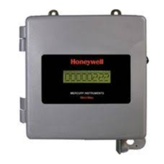
At the time of manufacturing, the ERX may be fabricated as a wall- mounted, pipe stand, or as a portable unit in an 800 series case, (three pressure default case) ERX Recorder (single pressure) or a Mini-AT (dual pressure) case. -
Page 6: Warranty
I, Division 1, Group D hazardous locations and Canadian Standards Associations (CSA) for use in Glass I, Division 1, Groups C & D hazardous locations. The ERX Recorder is recognized as intrinsically safe instrument when installed in accordance with UL control drawing 40-3332 or CSA control drawing 40-3332-A (see appendix). -
Page 7: Warning
Use of third-party battery packs voids product warranty, voids intrinsic safety certifications and may impair safety. Modes of Operations The ERX Recorder is in one of three operating modes. Each mode is well defined and suited to a particular purpose. Operating Modes: •... -
Page 8: Serial Access Mode
Palm Pilot, or Pocket PC and appropriate serial hardware connected to the instrument’s serial port. The user must enter a five-digit code access code (default 22222) to enter level two. www.honeywell.com ... -
Page 9: Instrument Access
LCD, and return to the ‘sleep mode’ to conserve energy. Other than time, the ERX Recorder will also wake-up due to either a serial link or push button activation. A wake-up caused by a serial communication link allows the recorder to communicate with serial devices connected to J5 or through a COMS I/O port. - Page 10 The 32 points of characterization are unique to each transducer and referred to as ‘Transducer Coefficients’. When replacing a transducer for any reason, the coefficients must be reloaded with the proper coefficients for the replacement transducer. www.honeywell.com ...
-
Page 11: Temperature System
Temperature System -40 to 150 (-40 to 65C) The temperature system consists of a highly stable solid-state transducer connected to the ERX main circuit board through a 6-foot Teflon cable. The stainless steel probe is ¼” in diameter and six inches in length; however, longer or shorter probe lengths are available options as well as an armor cable. -
Page 12: Audit Trail
Audit Trail The ERX Recorder is capable of storing either 4 or 10 items in its Audit Trail. Any of the recorder items may be placed in the Audit Trail. Default: 10 Audit Trail Items Interval 10 items 4 items... - Page 13 Default Audit Trail with P3 Voltage Monitor Audit Trail Report Item 1-10 Description of default Audit Trail items Item Description Item Description P3 Average Pressure Temperature Interval High P3 Interval High P3 Interval Low P1 Pressure Temperature Interval Low P2 Pressure P1 Current Day Average Case Temperature P1 Current Day High...
-
Page 14: Informational Display (Lcd)
Informational Display (LCD) A single 8-digit alphanumeric display (LCD) is a standard feature of the ERX. The LCD may be mounted externally without a window cover, externally with a window cover, or internally. A LCD is required for viewing the display lists 1 & 2 data and live readings. Normally the instrument is in the sample measurement mode and the LCD displays the primary transducer (P1) last sampled pressure, default setup. -
Page 15: Installation And Operation Of The Erx Recorder
Installation and Operation of the ERX Recorder Upon receiving the recorder, be sure that all items received are in good condition. Check the packing list to make sure the shipment is complete. Report to your Mercury Representative any damages and immediately file any shipping damage claims with the carrier who delivered the shipment. -
Page 16: Instrument Setup
Items 580 and 581 Site IDs are preprogrammed using the recorder’s serial number, set by the factory prior to shipping, but may be changed to meet company’s requirement. Site IDs must remain unique, that is, no two recorders should have the same Site ID numbers. www.honeywell.com ... -
Page 17: Using Masterlink32 Software
Using MasterLink32 Software: • Date and Time Instrument Set Inst. Date/Time via computer, ensure date and time is correct in the computer before setting date and time via computer. Manually set time by entering the time in item 582 Manually set the date by entering the date in item 583 •... -
Page 18: 2-Point Pressure Calibration (Defined)
2-point pressure calibration (items required) • ERX Recorder • Pressure source and fittings (capable of providing pressures of at least 50% of the ERX pressure transducer range) • Pressure Reference (accuracy to equal or exceed the accuracy of the ERX pressure system) •... -
Page 19: Two-Point Pressure Calibration (Absolute Transducers)
Obtain as many pressure samples as necessary until an acceptable pressure reading is displayed. If the ERX zero pressure reading is acceptable, click the SPAN button to change to the Span Calibration sequence. The screen title should have changed to “Pressure Span Calibration.” At this point, the software is waiting to sample the applied pressure. -
Page 20: Two-Point Pressure Calibration (Items Required)
Two-point pressure calibration (items required) • ERX • Pressure Source and fittings (capable of providing pressures of at least 50% of the ERX pressure transducer range) • Pressure Reference (accuracy to equal or exceed the accuracy of the ERX pressure system) •... - Page 21 CHANGE button when it becomes active. Enter the pressure value for the span reference pressure. As the computer screen updates, the ERX will calculate the required span gain, and store this calculated value within the instrument before returning to a live pressure reading.
-
Page 22: Two-Point Temperature Calibration
The Two-Point Calibration process uses the temperature offset and temperature span values to adjust for individual variations. Once these two points have been calculated and stored in memory, all other applied temperatures can be determined by a linear interpolation. www.honeywell.com ... -
Page 23: Alarm Pulses (Form-A)
Alarm Pulses (Form-A) The alarm output pulse is available as a Form-A output only. The alarm output pulse width is fixed at 50 mS and there is no need for pulse scaling. An alarm pulse output is a one-time occurrence, at the time any alarm becomes active. Subsequent alarm pulses will not occur until all previous alarms have been cleared. -
Page 24: Communicating To The Erx Recorder With A Modem
Communicating to the ERX Recorder with a Modem The ERX Recorder has a single I/O serial port that is used for local serial connections and for modem connections. The I/O serial port baud rate is controlled by item 588, is set to “Auto baud”... -
Page 25: Internal Or External Communications With A Rs-232 Case Connector
External Modem Communications without an External RS-232 Case Connector Requires the use of an optional RS-232 to CMOS I/O Board, 40-2717-2: See Messenger Modem manual for additional information. Internal or External Communications with a RS-232 Case Connector Requires the use of an optional RS-232 to CMOS I/O Board with shorting plug, 40-2717-3: (Shorting plug not shown) ... -
Page 26: Automatic Call-In Feature
The Alarm Call-In feature can be configured to call in two ways: 1is to use the alarm pulse output of the ERX Recorder to trigger the automatic call-in feature of the MI Modem. Once and an alarm condition has been detected by the recorder, the recorder will generate an alarm pulse, that will cause the MI Modem to jump into an alarm subroutine that has been pre-programmed in the MI Modem program. -
Page 27: At Commands Method
AT Commands Method The AT command method is accomplished by sending Hayes AT-type commands out the serial I/O port to a generic-type modem, such as the Messenger Modem. This method has the ERX recorder controlling the Hayes compatible modem. To use this method, set the following items:... -
Page 28: Alarm And Scheduled Call-In
Alarm and Scheduled Call-In The ERX Recorder, if configured, can initialize a call-in due to an alarm and a scheduled-call-in. In this method, item 338 (Scheduled Call-In Occurred) may be used by the host system to determine whether the call-in was triggered by an alarm or due to a scheduled call-in. A scheduled call-in will have changed item 338 from ‘0’... -
Page 29: 30-Minute Window Interval
If both items 792 or 793 is set to zero disables modem power control. 30-Minute Window Interval To power a communication device for a thirty-minute period that starts at 9:00 AM and ends at 9:30 AM, configure item 791 to 09 00 00 and item 783 to 09 30 00 and items 792 & 793 to 30 minutes. - Page 30 It is recommended, that if the Modem Power control interval is greater than 15 minutes per day, that the recorder has either, a dual battery pack, a Solar power supply, or an AC to DC power supply with battery backup. www.honeywell.com ...
-
Page 31: Digi-Span Fuel Switching Feature
An ERX connected to a Digi-Span module provides an automatic or manual fuel switching function when item 340 is enabled. This feature requires ERX’s Pulser-A output to be connected to the Digi-Span’s “Gas Override” terminal, the Pulser-B output connected to the “Oil Override”... -
Page 32: Firmware Upgrade
MasterLink32 software only. All data and configuration information is lost and the recorder is in a firmware default configuration after upgrading the firmware. NOTE: If the ERX has an optional pressure expansion board installed, discount the expansion board’s ribbon cable from J2 of recorder’s main circuit board prior to upgrading firmware Procedure to Upgrade ERX Recorder Firmware: Connect the MPA (40-2620) to J5 I/O port on the printed circuit board. - Page 33 Click Mini-Max, which generates the Open screen prompting for a location of the firmware text file and then drill to the file location by using Windows conventions. Once you have drilled to the location of the file, highlight the desired file and click Open, producing a Modal screen: Click Ok to establish a serial link to the recorder Click Begin, but do not select Pre-Firmware Upgrade Data Collection or Post-...
- Page 34 14. Discount link and re-link to recorder using MasterLink32 software and upload the item file created previously, then load Non-Cal Items and Cal Items to restore the configuration and calibration items. 15. Reset the date and time in recorder. 16. Verify the ERX Recorder has the proper configuration. www.honeywell.com ...
-
Page 35: Putting The Erx Recorder Into "Shutdown
In order to bring the ERX Recorder out of a complete shutdown, simply plug in the main battery and replace the super cap jumper. It will be necessary to reset the date, time, and other items that are not current. -
Page 36: Taking The Erx Recorder "Un-Configured
MasterLink32 software. There are two methods to put an ERX Recorder in un-configured state. The first is with MasterLink32 Software, and the second is a hardware method that is useful if a serial link cannot be established. -
Page 37: Hardware Method--If Serial Link Cannot Be Established
MI button for at least 10 seconds. You should see Button Down on the display. To reset the recorder to ERX firmware defaults, release the MI button when the display reads REL 4D FLT or to restore the recorder to its preconfigured configuration continue to hold the MI button until the display reads DISPLAY TEST, then RESTORE, release MI button. -
Page 38: Parameter Item List
Mercury Instruments ERX Recorder are listed below. When connected and linked to a computer, all ERX Recorder items can be displayed or changed in the Display/Item by Function of MasterLink32 software. -
Page 39: P1 Pressure Coefficients
Pressure Coefficients P1 Pressure Coefficient 1 0.000000 P1 Pressure Coefficient 2 30.00000 P1 Pressure Coefficient 3 0.000000 P1 Pressure Coefficient 4 0.000000 P1 Pressure Coefficient 5 0.000000 P1 Pressure Coefficient 6 30.00000 P1 Pressure Coefficient 7 0.000000 P1 Pressure Coefficient 8 0.000000 P1 Pressure Coefficient 9 0.000000... -
Page 40: P2 Pressure Coefficients
Scheduled Call-In Phone # Phone number used for scheduled call-in. Digi-Span Mode Selection that determines what mode the ERX Recorder pulse output channels are set to. Default: 0 = No Digi-Span--Standard Pulse Out 1 = Gas Override--Pulse Channel A on... - Page 41 P2 Pressure Coefficient 26 30.00000 P2 Pressure Coefficient 27 0.000000 P2 Pressure Coefficient 28 0.000000 P2 Pressure Coefficient 29 0.000000 P2 Pressure Coefficient 30 30.00000 P2 Pressure Coefficient 31 0.000000 P2 Pressure Coefficient 32 0.000000 P3 Pressure Unit Selection for the unit-of-measure for P2 pressure item 501, if changed to a different type, all P2 pressure-related items are converted and displayed to the new unit-of-measure.
- Page 42 P3 Maximum Pressure Time Time of maximum P3 pressure reading was recorded since the recorder was last reset. Default: 00 00 00 P3 Maximum Pressure Date Date of the maximum P3 pressure reading since the recorder was last reset. Default: 01-01-04 www.honeywell.com ...
-
Page 43: Board Coefficients
Item Item Name & Description P3 Minimum Pressure Minimum P3 pressure reading recorded since the recorder was last reset. Default: 333.00 P3 Minimum Pressure Time Time of minimum P3 pressure reading was recorded since the recorder was last reset. Default: 00 00 00 P3 Minimum Pressure Date Date of the minimum P3 pressure reading since the recorder was last reset. - Page 44 549. Default: 0.00 P2 Gas Pressure The last recorded measurement of gas pressure from the primary pressure transducer and scaled to the selected pressure units at item 550. Default: 0.00 Item Item Name & Description Temperature www.honeywell.com ...
- Page 45 The last recorded measurement of gas temperature and is scaled to the selected temperature units at 551. Default: -40.00 Case Temperature The last recorded measurement of the air temperature inside the recorder, considered an ambient temperature measurement. Default: -40.00 Case Maximum Temperature The highest recorded case temperature measurement since the recorder was last reset.
- Page 46 The date automatically obtained form item 583 at the time of the P1 pressure zero calibration. Default: 01-01-04 Temperature Calibration Date The date automatically obtained form item 583 at the time of the temperature zero calibration. Default: 01-01-04 Battery Voltage Reading Battery voltage reading obtained during the most recent wake-up. www.honeywell.com ...
- Page 47 Item Item Name & Description Battery Low Volt Limit Voltage limit at which the recorder will automatically generate a low voltage alarm if the battery reading, reads below limit. Default: 4.30 Shutdown Voltage Limit The voltage level at which “..H.E.L.P..” is displayed on the LCD as an indication that the battery is about dead and needs to be replaced.
- Page 48 See below for possible temperature unit choices. Code Value Default: 0 Fahrenheit Celsius Rankine Kelvin Pressure Display Resolution This item controls the how many decimal place that recorder will displayed and applies to all pressure units. Code Value XXXXXXXX. XXXXXXX.X Default: 2 XXXXXX.XX XXXXX.XXX www.honeywell.com ...
- Page 49 Item Item Name & Description P1 Pressure High Alarm Limit The pressure reading that automatically produces a high-pressure alarm. This value is a user selectable item and is normally set somewhere between 50 & 100% of transducer range. Default: 111.00 P1 Pressure Low Alarm Limit The pressure reading that automatically produces a low-pressure alarm.
- Page 50 The upper pressure range limit, automatically scaled to the pressure units selected at item 549. If PSI is the selected pressure units, then item 572 will be the same as item 571. NOTE: The value at item 572 may be manually edited to a rounded-off number, if desired. Default: 111.00 www.honeywell.com ...
- Page 51 Item Item Name & Description P2 Pressure Range User The upper pressure range limit, automatically scaled to the pressure units selected at item 550. If PSI is the selected pressure units, then item 573 will be the same as item 572. NOTE: The value at item 573 may be manually edited to a rounded-off number, if desired.
- Page 52 User selected time period that determines how often the recorder will wake up to measure (sample) the analog inputs, i.e., P1, P2, P3 T, Case Temp, and Battery Voltage. Code Value 60 Seconds 30 Seconds 15 Seconds Default 3 10 Seconds www.honeywell.com ...
-
Page 53: Audit Report Items-Default
Item Item Name & Description Start Time A user selected time of day when selected items are re-zeroed and the next day’s calculations begin. Generally the "Start Time" is set to midnight to coincide with the calendar day, but other top of the hour times may be entered. Default: 00 00 00 Instrument Baud Rate Codes (0-8) are to select the instrument’s baud rate for all local serial connection. -
Page 54: P3 Pressure Coefficients 1-26
P3 Pressure Coefficient 4 0.000000 P3 Pressure Coefficient 5 0.000000 P3 Pressure Coefficient 6 30.00000 P3 Pressure Coefficient 7 0.000000 P3 Pressure Coefficient 8 0.000000 P3 Pressure Coefficient 9 0.000000 P3 Pressure Coefficient 10 30.00000 P3 Pressure Coefficient 11 0.000000 www.honeywell.com ... - Page 55 Item Item Name & Description P3 Pressure Coefficient 12 0.000000 P3 Pressure Coefficient 13 0.000000 P3 Pressure Coefficient 14 30.00000 P3 Pressure Coefficient 15 0.000000 P3 Pressure Coefficient 16 0.000000 P3 Pressure Coefficient 17 0.000000 P3 Pressure Coefficient 18 30.00000 P3 Pressure Coefficient 19 0.000000 P3 Pressure Coefficient 20...
- Page 56 The date the recorder’s maximum T1temperature sample reading occurred, since the recorder was last reset. Default: 01-01-04 Temperature Minimum Time The time the recorder’s minimum T1 temperature sample reading occurred, since the recorder was last reset. Default: 00 00 00 www.honeywell.com ...
- Page 57 Item Item Name & Description Temperature Minimum Date The time the recorder’s minimum T1 temperature sample reading occurred, since the recorder was last reset. Default: 01-01-04 P1 highest pressure reading that occurred during the interval. Default: -1.00 P1 Interval Low P1 lowest pressure reading that occurred during the interval.
- Page 58 The date at which the recorder’s minimum T1 temperature sample reading (item 656) that occurred during the interval. Default: 01-01-04 P1 Current Day Average Recorder’s average P1 sampled pressure readings that occurred during the current day. Default: -1.00 www.honeywell.com ...
- Page 59 Item Item Name & Description The maximum P1 pressure sampled readings that occurred during the current day. Default: -1.00 P1 Current Day Low The minimum P1 pressure sampled readings that occurred during the current day. Default: 9999.99 P2 Current Day Average Recorder’s average P2 sampled pressure readings that occurred during the current day.
- Page 60 The date at which the recorder’s minimum T1 temperature reading (item 678) occurred during the current day. Default: 01-01-04 P1 Previous Day Average Pressure Recorder’s average P1 sampled pressure readings that occurred during the previous day. Default: -1.00 www.honeywell.com ...
- Page 61 Item Item Name & Description P1 Previous Day High Pressure Recorder’s maximum P1 sampled pressure readings that occurred during the previous day. Default: -1.00 P1 Previous Day Low Pressure Recorder’s minimum P1 sampled pressure readings that occurred during the previous day.
- Page 62 The time at which the recorder’s minimumT1 sampled temperature reading (item 699) occurred during the previous day. Default: 00 00 00 Temperature Previous Day Low Date The date at which the recorder’s minimum T1 sampled temperature reading (item 699) occurred during the previous day. Default: 00 00 00 www.honeywell.com ...
- Page 63 Code Value Default: 0 Send all errors Time-out error 21 not sent Timeout Delay 1 Time in seconds that ERX waits for the host computer to send an ENQ, following an EOT before issuing an error 21. Default: 25 ...
- Page 64 Item Item Name & Description Timeout Delay 2 Time in seconds that ERX waits for the host computer to send an ENQ, following an EOT before issuing an error 21. Default: 25 RBX Alarm Event Indication of a RBX alarm activity since the recorder was last interrogated.
- Page 65 Item Item Name & Description Modem AT Enable Selection to that determines the type of call-in initiated by the recorder. Code Value Call-in via alarm pulse Default:1 Call-in via AT commands Parameter used to set the amount of time to leave the system powered up after a call-in (allowing time for the host to call-back).
- Page 66 The low/low alarm feature adds an additional alarm notice, that is, in addition to the normal low alarm limit set by item 556 and even lower alarm limit may be set, which creates a two-step alarm notification. Default: -1.00 P2 High/High Alarm Code Value Default: 00000000 No alarm 11111111 Alarm www.honeywell.com ...
-
Page 67: Erx Hazardous And Non-Hazardous Installation Drawings
Item Item Name & Description P2 Low/Low Alarm Code Value Default: 00000000 No alarm 11111111 Alarm Modem Wake-up Delay Default: 50, Tenths of second ... - Page 68 www.honeywell.com ...
- Page 69 ...
- Page 70 ...
- Page 71 ...
- Page 72 ...
- Page 73 ...
- Page 74 ...
- Page 75 ...
- Page 76 ...
- Page 77 ...
- Page 78 ...
- Page 79 ...
- Page 80 ...
- Page 82 www.honeywell.com...
- Page 84 Find Out More: To learn more about Mercury Instruments products, contact your Honeywell Process Solutions representative, visit www.mercuryinstruments.com or call 513-272-1111. Automation and Control Solutions Honeywell Process Solutions 3940 Virginia Ave. Cincinnati, OH 45227 MNL-ERX-1 513-272-1111 October 2010 www.honeywell.com © 2010 Honeywell...