
Related Manuals for Fuji Electric FVR-C9S-7UX

Summary of Contents for Fuji Electric FVR-C9S-7UX
- Page 1 FVR-C9S-7UX Instruction Manual FVR-C9S-7UX Drive Series Single-phase 240 V AC Input Type...
- Page 2 • Please make sure that this instruction manual accompanies the drive to the end user. • Keep this instruction manual so that it will always be available for the duration of the drive’s operating life. • Product specifications are subject to change without notice. FVR-C9S-7UX...
-
Page 3: Table Of Contents
Thank you for purchasing the Fuji “FVR-C9S” drive marketed by GE Fuji Drives USA, Inc. This instruction manual is included with the drive and equipment and is provided for the conve- nience of the end user. Please be sure it accompanies the drive. -
Page 4: Safety Precautions
IP54. Required for CE Certification. WIRING WARNING: FIRE AND ELECTRIC SHOCK HAZARD. When connecting the drive to a power supply, be sure to connect it via a circuit breaker, a leakage current breaker or a fuse, otherwise fires may result. - Page 5 OPERATION WARNING: ELECTRIC SHOCK HAZARD Always install the drive cover before turning on the power supply. In addition, do not remove the drive cover while the power is on. Failure to observe these precautions may result in electric shocks. Do not operate any of the switches with wet hands, otherwise electric shocks may result.
-
Page 6: Inspection Upon Receipt
FVRF12C9S-7UX FVRF25C9S-7UX FVRF50C9S-7UX FVR001C9S-7UX FVR002C9S-7UX FVR-C9S-7UX Field wiring connection shall be made by a UL listed and CSA Certified closed-loop terminal connector sized for the wire gauge involved. Connector must be fixed using the crimp tool specified by the connector manufacturer. -
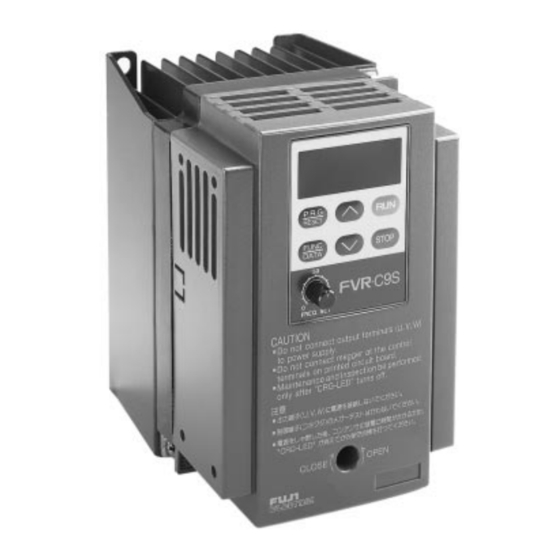
Page 7: Part Names
(Permissible voltage: AC220V - 240V) 2. Do not connect power supply to the drive output terminals (U, V, W). Connect power supply only to the power terminals (L1, L2) 3. -
Page 8: Specifications
3) This applies to the case where momentary power failure occurs under such conditions that rated voltage is inputted and load factor is 85%. 4) Shows the case where an applicable motor equipped with an AC reactor (option) on the input side is used. FVR-C9S-7UX [Hp] [kVA] 0.27... - Page 9 Environment Vibration Storage temperature Atmospheric pressure Enclosure Cooling method 5) This indicates average braking torque of a single motor. (Value varies according to motor efficiency. FVR-C9S-7UX [Hp] Key operation: Setting with UP/DOWN keys Potentiometer: Terminal for 1-5K ohm VR is provided...
-
Page 10: External Dimensions
2 - 0.20 X 0.24 (2 - 5 X 6.2) 0.39 (10) 2.36 (50) Rated Current Type FVRF12C9S-7UX FVRF25C9S-7UX FVRF50C9S-7UX FVR001C9S-7UX FVR-C9S-7UX 0.24 (6.2) 0.26 (6.5) 0.43 (11) 0.06 (1.5) 0.39 (10) DWG 1: FVRF12C9S-7UX to FVROO1C9S-7UX External Dimensions: inches (mm) 0.66 3.37 (85.5) 0.89 (22.5) - Page 11 3.86 (98) 2 - dia. 0.20 (2 - dia. 5) 0.20 (5) 0.45 (11.5) 3.43 (87) Rated Current Type FVR002C9S-7UX FVR-C9S-7UX 0.24 (6.2) 0.24 (6.2) 0.18 (4.5) 0.43 (11) 0.45 (11.5) DWG 2: FVR002C9S-7UX External Dimensions: inches (mm) 5.53 (140.5) 3.05 (77.5)
-
Page 12: Installation Instructions
Space: The drive will generate heat during operation. Allow sufficient space around the unit as shown in the above figure. FVR-C9S-7UX Mounting plate: Heat sink temperature will reach +90 C during operation. Please use thermostable material for drive mounting plate. - Page 13 CN2 on the drive main unit are connected. FVR-C9S-7UX Note 3) Connect the power supply of over Disconnect CN 1 CN 2 5) Reinstall the cover. Connect the harness CRG Lamp...
-
Page 14: Basic Wiring Diagrams
STOP keys on the keypad panel. Power Supply AC220 - 240V 50/60 Hz 1-phase * PE terminal blocks for the drive and motor should be provided in the cabinet in which the drive is installed in. FVR-C9S-7UX 8 8 8 10V 1mA E(G) Fault... - Page 15 * PE terminal blocks for the drive and motor should be provided in the cabinet in which the drive is installed in. FVR-C9S-7UX Thermal Relay 8 8 8...
-
Page 16: Application Of Wiring And Equipment
Listed fuse* * The use of quick-acting fuses is required to validate UL listing. The factory recommendation is Bussman type JKS or equivalent. FVR-C9S-7UX Long wiring lengths between the motor and the drive will result in increased capacitance and leakage current. This may cause earlier... -
Page 17: Terminal Function Explanation
Grounding terminal of drive chassis (case). Be sure to ground the drive to prevent electric shock or to lower noise Used as a power supply for frequency setter (variable resistor: 1 - 5K ohm) (DC + 10V, 10mA max) DC 0 - +10V / 0 - 100% (Input resistance: 22K ohm) - Page 18 Output for Motor Contact 30A, B, C Output FVR-C9S-7UX Terminal Name Outputs + 10VDC between FM and CM terminals. When frquency setting is equal to the maximum frequency setting, Analog Monitor outputs + 10VDC at 150% current when monitoring output current.
-
Page 19: Operation
RUN/STOP Method • RUN/STOP by keypad panel operation (Factory preset at the time of shipment F02:0). FVR-C9S-7UX • The drive is shipped with a factory in- stalled jumper, between FWD-CM. Only forward operation is possible. To enable reverse operation, remove the jumper from FWD/CM and install the jumper between REV-CM. - Page 20 (operation by external signal, FWD/REV terminals) 0 2 = * The frequency setting rate of change increases when FUNC/DATA key and UP/DOWN keys are pressed simultaneously FVR-C9S-7UX RUN/STOP Frequency Setting UP/DOWN Keys* Analog signal (DC0 - 10V) UP/DOWN Keys* Analog signal (DC0 - 10V)
-
Page 21: Keypad Panel
When F01 is _ _ 0: Press UP to increase frequency; press DOWN to decrease frequency. Note) If FUNC/DATA is pressed while pressing UP or DOWN, frequency changing speed increases. 4) Function setting method FVR-C9S-7UX 8. 8. 8. RESET FUNC... - Page 22 Method FVR-C9S-7UX Operation Procedure Press this key to switch to the PRG/RESET program setting mode. Press UP key or DOWN key to UP/DOWN select function code Press this key to display function FUNC/DATA code. Press UP key or DOWN key to UP/DOWN change function code data.
-
Page 23: Function Explanation
Setting Signal 1: For 0 - 5 V DC Brake (Level 0 - 100% Setting) DC Brake (Time) 0.0 (inactive) 0.1 - 30s Starting Frequency 1 - 6 Hz FVR-C9S-7UX Date Code Range Change Min. Factory Unit During Set. Setting Operation —... - Page 24 Meter Output selection *1 Frequency can be set in increments of 0.1 Hz within a range of 0.0 to 99.9 Hz, and can be set in increments of 1 Hz FVR-C9S-7UX Date Code Range 0 - 5 (code) The current and previous 3 fault events are displayed...
- Page 25 0. 0 The time required to reach the maximum output frequency can be set within a range of 6 0. 0 0.0s to 60s (in increments of 0.1s). Note: 0.0s setting is taken for 0.01s for acceleration and 0.1s for deceleration. FVR-C9S-7UX Maximum frequency...
- Page 26 0 Setting range: 30 to 105% (increments of 1%) Setting value (%) = K X Drive Capacity F12C9S-7UX F25C9S-7UX F50C9S-7UX 001C9S-7UX 002C9S-7UX FVR-C9S-7UX Motor's rated current X 100 Drive's rated current Wiring Length : feet 1 3 0 1 6 5 K = 1.2...
- Page 27 90 - 80 - 70 - 60 - 50 - 40 - 30 - 20 - 10 - Drive frequency (Hz) FVR-C9S-7UX 110 - 105% 100 - 90 - 80 - 70 - 60 - 50 - 40 - 30 -...
- Page 28 F 1 0 Restart After Momentary Power Failure It is possible to select whether or not to restart operation when power supply is resumed after momentary power failure. 0 Inactive 1 Active F 1 1 Gain for Frequency Setting Signal Outputs a frequency which is a proportional ratio of the analog frequency setting.
-
Page 29: Starting Frequency
The information for any new trip will be stored in the area for the "information for the latest trip" shown above, each trip history will be removed downward and the "information for the third preceding trip" will be erased. FVR-C9S-7UX Output frequency... - Page 30 F 2 3 Jump Frequency 3 Frequency is jumped so that the mechanical common point of load and the output frequency of drive do not coincide with each other. Output frequency FVR-C9S-7UX Jump Width Jump width is changeable within Set frequency 0-10 Hz range in a unit of 1 Hz.
- Page 31 This function enables terminal BX to be used for two different functions by changing the data code as follows: 0 Motor coast-to-stop command input 1 Multistep speed selection (X2) This function data cannot be changed during operation. (Possible to change only in STOP mode). FVR-C9S-7UX 100% Output frequency...
- Page 32 (Note 2) In selecting THR/BX terminal function (F27, F28) individual setting is possible. Terminal / Function Code Speed 0 Frequency setting is made by either the analog signal or the keypad panel. THR-CM (X1) BX-CM (X2) FWD-CM FVR-C9S-7UX F27 : 1 F27: 0 F28: 0 F28: 1 External Alarm input Motor coast-to-stop...
- Page 33 Note: The FM terminal output is a pulse output of which frequency is constant (38.1 Hz) and duty is variable. F 3 3 FM Terminal Function Selection With regard to the data outputted to the FM terminal, either the output frequency or the output current can be selected. 0 Output frequency 1 Output current FVR-C9S-7UX...
-
Page 34: Protective Functions
Detects overload of drive and stops drive. Memory Error Stops drive in case of memory error CPU Error Stops drive in case of a CPU error * This output is selectable by F10 FVR-C9S-7UX Explanation Display Alarm Output Yes* C92-05... -
Page 35: Warranty Parts And Service
24-hour Emergency 1-540-387-8292 Warranty Coverage The warranty set forth in Section 1 of FN-1090 (1/91) of GE’s Condition of Sale covers all major parts of the drive such as the main printed circuit boards, transistor modules, etc. The warranty covers replace- ment of the entire drive. - Page 36 After all of the Checklist information is acquired, contact the following Service Center number for assistance: 540-387-5739 (8am - 5pm Central Standard time Monday thru Friday). 540-387-8292 (24-hour emergency) When you return the unit for warranty you need to get a RMA number from your Service Center. FVR-C9S-7UX Running Accel If Yes:...
-
Page 37: Electromagnetic Compatibility
European Commission Guidelines Document on Council Directive 89/336/EEC, Fuji Electric Co., Ltd. has chosen to classify the FVR-C9S-7UX range of drives as “Com- plex Components”. Classification as “Com- plex Components” allows a product to be treated as “apparatus”, and thus permits... - Page 38 FVRF25C9S-7UX EFL-0.75C9-7 FVRF50C9S-7UX FVR001C9S-7UX EFL-2.2C9-7 FVR002C9S-7UX FVR-C9S-7UX 8) FVR drives should be installed, and are designed to operate, within an electrically shielded metal enclosure. The RFI filters range are designed especially for the FVR drive and help to ensure EMC compliance of machinery an installations using the drives.
- Page 39 Screening must be electrically continuous and earthed at the enclosure and the motor. *1and *2: These connections are to be as short as possible and earth conductor should be as thick as possible. FVR-C9S-7UX Enclosure Ferrite ring Noise filter...
- Page 40 Power supply single-phase 220-240V 50/60 HZ Frequency setting Potentiometer Analog frequency meter Fig. 3 Recommended installation detail inside the enclosure FVR-C9S-7UX FILTER L’ N’ Alarm Signal [13] [12] [11] [FM] [CM] Enclosure Housing Ferrite ring Motor Armored or screened cable...
- Page 41 FVR-C9S-7UX...
-
Page 42: Ec Declaration Of Conformity
When : Wired and earthed in accordance with the installation instructions. Installed within a steel enclosure. Used in conjunction with power input filter and ferrite rings which are recommended by Fuji Electric. FVR-C9S-7UX Inverter Fuji Electric FVRO.1C9S-7xxx to FVR1.5C9S-7xxx (xxx stands for A to Z) A. - Page 43 When : Wired and earthed in accordance with the installation instructions. Installed within a steel enclosure satisfied “Pollution degree 2”. Used in conjunction with 1AC power supply (Line) whose line is earthed for -7xxx series. FVR-C9S-7UX A. OKUBO General Manager...
- Page 44 FVR-C9S-7UX GE Fuji Drives USA, Inc. 1501 Roanoke Blvd. Suite 435 Salem, VA 24153 1-800-543-6196 Internet Address: http://www.ge.com INR Si47-0459 b-E Printed in Japan...