HP R1500 - UPS XR User Manual
Ups r1500 xr models user guide
Hide thumbs
Also See for R1500 - UPS XR:
- User manual (115 pages) ,
- Product end-of-life disassembly instructions (12 pages) ,
- Installation instructions manual (9 pages)

Related Manuals for HP R1500 - UPS XR


Summary of Contents for HP R1500 - UPS XR
-
Page 1: User Guide
HP Uninterruptible Power System R1500 XR Models User Guide August 2002 (Second Edition) Part Number 217823-002... - Page 2 Hewlett-Packard Company shall not be liable for technical or editorial errors or omissions contained herein. The information in this document is provided “as is” without warranty of any kind and is subject to change without notice. The warranties for HP products are set forth in the express limited warranty statements accompanying such products.
-
Page 3: Table Of Contents
Contents About This Guide Audience Assumptions ..........................vii Important Safety Information ........................vii Symbols on Equipment..........................vii Rack Stability............................. viii Symbols in Text............................viii Related Documents............................ viii Getting Help..............................ix Technical Support ..........................ix HP Website............................ix Authorized Reseller..........................ix Reader’s Comments............................. - Page 4 Contents Audible Alarms ............................2-6 Silencing an Audible Alarm ....................... 2-6 Shutting Down the System........................2-6 Chapter 3 Configuration Placing the UPS in Configure Mode ......................3-1 Configuration Parameters.......................... 3-2 Changing Configuration Parameters....................3-3 Chapter 4 Battery Maintenance Precautions ..............................4-1 Charging Batteries.............................
- Page 5 Contents Appendix B Electrostatic Discharge Grounding Methods ..........................B-1 Appendix C Specifications Physical Specifications ..........................C-1 Input Specifications ..........................C-2 Output Specifications..........................C-3 Battery Specifications ..........................C-4 Environmental Specifications ........................C-4 Index HP Uninterruptible Power System R1500 XR Models User Guide...
-
Page 7: About This Guide
About This Guide This guide provides step-by-step instructions for configuration, and reference information for operation, battery maintenance, and troubleshooting for the Uninterruptible Power System (UPS). Audience Assumptions This guide is intended for individuals requiring information about the use of HP UPSs. HP assumes you are qualified in the servicing of computer equipment and trained in recognizing hazards in products with hazardous energy levels. -
Page 8: Rack Stability
About This Guide Rack Stability WARNING: To reduce the risk of personal injury or damage to the equipment, be sure that: • The leveling feet are extended to the floor. • The full weight of the rack rests on the leveling jacks. •... -
Page 9: Getting Help
About This Guide Getting Help If you have a problem and have exhausted the information in this guide, you can get further information and other help in the following locations. Technical Support In North America, call the HP Technical Support Phone Center at 1-800-652-6672. This service is available 24 hours a day, 7 days a week. -
Page 10: Overview
Overview This chapter contains a general overview of the HP UPS, including an introduction to the model configurations, power management software, available hardware options, and warranties. Read this chapter to become familiar with the features of the UPS before operating the unit. Standard UPS Features The following features make this UPS versatile and easy to use: •... -
Page 11: Network Transient Protector
Overview Network Transient Protector The UPS includes a Network Transient Protector (NTP) that provides surge protection for connected communication devices. CAUTION: To avoid damaging the equipment, do not connect the Network Transient Protector to a digital PBX line. Connect either to an analog phone line or to a network. Overcurrent Protection Select models feature overcurrent protection provided through resettable circuit protectors located on the UPS rear panel. -
Page 12: Front Panel
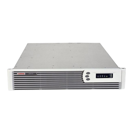
Overview Front Panel The front panel of the UPS is shown in Figure 1-1. Figure 1-1: Front panel configuration Battery compartment Control buttons LED display For detailed information on using the control buttons and LED indicators, refer to the section, “Front Panel Controls and LED Indicators,”... -
Page 13: Rear Panels
Overview Rear Panels The rear panel configurations of the UPS are shown in Figures 1-2, 1-3, and 1-4. Figure 1-2: Rear panel of R1500 XR NA Communications port/option slot Load segment circuit protectors Load segment 2 (three NEMA 5-15 receptacles) Load segment 1 (three NEMA 5-15 receptacles) Network Transient Protector OUT jack Network Transient Protector IN jack... - Page 14 Overview Figure 1-3: Rear panel of R1500 XR JPN Communications port/option slot Load segment circuit protectors Load segment 2 (three NEMA 5-15 receptacles) Load segment 1 (three NEMA 5-15 receptacles) Network Transient Protector OUT jack Network Transient Protector IN jack REPO port Power cord with NEMA 5-20 plug ERM connector...
- Page 15 Overview Figure 1-4: Rear panel of R1500 XR H INT’L Communications port/option slot Circuit protector IEC-320-C14 input power receptacle Load segment 1 (three IEC-320-C13 receptacles) Load segment 2 (three IEC-320-C13 receptacles) Network Transient Protector OUT jack Network Transient Protector IN jack REPO port ERM connector Ground bonding screw...
-
Page 16: Power Management Software
Overview Power Management Software Power management software ensures maximum power reliability of HP computer systems through comprehensive control of HP UPSs. Specifically, power management software performs the following: IMPORTANT: Not all UPSs are equipped to support the entire feature set listed. •... -
Page 17: Remote Emergency Power Off Port
Overview Remote Emergency Power Off Port The UPS includes an isolated REPO port. The REPO feature allows the UPS to be powered down from a remote location. To use this feature, the REPO port must be connected to a remote, normally open switch (not supplied). When this switch is closed, the UPS immediately disconnects power from its load segments. -
Page 18: Pre-Failure Battery Warranty
Overview Pre-Failure Battery Warranty For specific information on the battery warranty, refer to the section, “Pre-Failure Battery Warranty,” in Chapter 4. HP Uninterruptible Power System R1500 XR Models User Guide... -
Page 19: Operation
Operation This chapter contains information on operating the UPS. Topics include the front panel controls, LED indicators, and modes of operation. Knowledge of these features is helpful when configuring and troubleshooting the unit. NOTE: For installation considerations and procedures, refer to the instructions included with the UPS. Copies of this document can be downloaded from www.hp.com. -
Page 20: Modes Of Operation
Operation continued Item Description Meaning/Function Utility LED ( ) Flashing Red—Utility input voltage is outside the +20% to -30% configured nominal range. Green—Utility voltage is present and output is on, or utility voltage has returned to the voltage range for which the UPS has been configured (UPS is supplying utility power and the audible alarm should be reset). -
Page 21: Charging The Batteries
Operation Charging the Batteries When the UPS is in Standby mode, allow the batteries to charge before putting the UPS into service. IMPORTANT: The batteries charge to: • 90 percent of their capacity within 3 hours • 100 percent of their capacity within 24 hours Charge the batteries for at least 24 hours before supplying backup power to devices. -
Page 22: Returning To Standby Mode
Operation Returning to Standby Mode When the UPS is in Operate mode (the Utility LED is solid green), press and hold the Standby button (1) until the audible alarm sounds. The Utility LED (2) flashes, and power to the loads ceases. 100% Figure 2-3: Placing the UPS in Standby mode IMPORTANT:... -
Page 23: Initiating A Self-Test
Operation Initiating a Self-Test To initiate a self-test, press and hold the Test/Alarm Reset button (1) for three seconds. Figure 2-4: Test/Alarm Reset button Because a portion of the self-test requires battery power, the self-test cannot be initiated if the batteries are less than 90 percent charged. -
Page 24: Audible Alarms
Operation Audible Alarms The UPS may sound an audible alarm to warn of a problem. For information on what to do if the UPS detects an alarm condition, refer to Chapter 5, “Troubleshooting.” Silencing an Audible Alarm To silence an audible alarm, press the Test/Alarm Reset button (1). Figure 2-5: Test/Alarm Reset button IMPORTANT: •... -
Page 25: Placing The Ups In Configure Mode
Configuration This chapter contains information on configuring the UPS. Proper configuration of the UPS is important in performing other functions on the unit, such as maintaining the battery and troubleshooting alarms. Placing the UPS in Configure Mode The UPS can enter Configure mode while in Operate or Standby mode. To place the UPS in Configure mode: 1. -
Page 26: Configuration Parameters
Configuration 2. Press and hold the Configure button (1) for three seconds. When the Configure button is released, the front panel configuration parameters flash in unison and the Configure Mode On LED (2) illuminates solid green. Figure 3-2: Placing the UPS in Configure mode Configuration Parameters In Configure mode, the front panel LED display changes function to allow UPS monitoring. -
Page 27: Changing Configuration Parameters
Configuration Table 3-2: Available Voltage Settings UPS Model Available Settings Parameter (LED) Utility Voltage (VAC) R1500 XR NA On Battery ( 120 (default) Bad Battery/Low Battery ( Site Wiring Fault Indicator ( R1500 XR JPN General Alarm ( ) R1500 XR H INT’L On Battery ( 230 (default) Bad Battery/Low Battery (... - Page 28 Configuration 2. To advance to the appropriate voltage configuration (to the right), press the On button (3). The selected voltage configuration LED flashes. Activate the voltage configuration by pressing the Standby button (2). The previously selected configuration parameter LED turns off. NOTE: Only one nominal utility voltage can be configured.
-
Page 29: Battery Maintenance
Battery Maintenance This chapter contains information for properly maintaining batteries for the UPS, including battery charging, replacement, disposal procedures, and warranties. Precautions WARNING: There is a risk of personal injury from the hazardous energy levels associated with UPS batteries. The maintenance and replacement of batteries must be carried out by an authorized service representative. -
Page 30: Determining When To Replace Batteries
Battery Maintenance Determining When to Replace Batteries When the Bad Battery/Low Battery LED (1) illuminates red, batteries may need to be replaced within 30 to 60 days. 100% Figure 4-1. Bad Battery/Low Battery LED To check a battery alarm, initiate a UPS battery self-test to verify that battery replacement is required. -
Page 31: Replacing Batteries
Battery Maintenance Replacing Batteries There are two options for replacing UPS batteries: • Powering down the UPS before removing the batteries • In certain circumstances, replacing the batteries without powering down the UPS CAUTION: While replacing the batteries without powering down the UPS, the UPS is not protected in the event of a utility power failure. - Page 32 Battery Maintenance 2. Remove the plastic battery cover plate, as featured in select models. Figure 4-3: Removing the battery cover plate 3. Remove the two screws to obtain access to the battery pack. Figure 4-4: Removing the two screws HP Uninterruptible Power System R1500 XR Models User Guide...
- Page 33 Battery Maintenance 4. Disconnect the battery cable from the circuit board located on the right side of the UPS (1). Unfasten the cable wires from the clasp and remove the wires without disturbing the pedestal or the user interface (2). Figure 4-5: Disconnecting the battery cable from the circuit board WARNING: The UPS R1500 XR battery pack weighs 11 kg (24 lb).
-
Page 34: Installing A New Battery Pack
Battery Maintenance Installing a New Battery Pack To install a new battery pack, reverse the steps in “Removing the Battery Pack,” in this chapter. Testing the New Battery Pack After installing the new battery pack, press the Test/Alarm Reset button. For information on initiating a self-test, refer to the section, “Initiating a Self-Test,”... -
Page 35: Care And Storage Of Batteries
Battery Maintenance Care and Storage of Batteries To maximize the life of batteries: • Minimize the amount of time the UPS uses battery power by matching the UPS configuration with the utility voltage. For more information, refer to Chapter 3, “Configuration.”... -
Page 36: Troubleshooting
Troubleshooting This chapter serves as a troubleshooting guide when problems occur with the UPS. Solutions for UPS problems that occur both during and after startup are covered. Troubleshooting If problems occur when starting or using the UPS, refer to Table 5-1 for possible causes and suggested actions. - Page 37 Troubleshooting Table 5-1: Troubleshooting continued Symptom Possible Cause Suggested Action The Utility LED ( ) is The utility input voltage is above No action is required. When the utility red. the normal range and the UPS input voltage returns to normal, the is in Buck mode.
- Page 38 Troubleshooting Table 5-1: Troubleshooting continued Symptom Possible Cause Suggested Action The On Battery LED The UPS is running on battery Save your current work and prepare to ( ) is red and an power. power down the system. audible alarm sounds. The On Battery LED The output voltage is out of Contact an authorized service provider.
-
Page 39: Repairing The Ups
Troubleshooting Table 5-1: Troubleshooting continued Symptom Possible Cause Suggested Action The UPS frequently There are variations in utility The utility voltage is frequently outside switches between power. the UPS operating range. Update the utility and battery configuration. power. Contact a qualified electrician to verify that the utility power is suitable for the UPS. -
Page 40: Regulatory Compliance Notices
Regulatory Compliance Notices Regulatory Compliance Identification Numbers For the purpose of regulatory compliance certifications and identification, your product has been assigned a unique series number. The series number can be found on the product nameplate label, along with all required approval markings and information. When requesting compliance information for this product, always refer to this series number. -
Page 41: Class B Equipment
Modifications The FCC requires the user to be notified that any changes or modifications made to this device that are not expressly approved by Hewlett-Packard Company may void the user’s authority to operate the equipment. HP Uninterruptible Power System R1500 XR Models User Guide... -
Page 42: Cables
Regulatory Compliance Notices Cables Connections to this device must be made with shielded cables with metallic RFI/EMI connector hoods in order to maintain compliance with FCC Rules and Regulations. Canadian Notice (Avis Canadien) Class A Equipment This Class A digital apparatus meets all requirements of the Canadian Interference-Causing Equipment Regulations. -
Page 43: Japanese Notice
Regulatory Compliance Notices Japanese Notice China Taiwan Notice HP Uninterruptible Power System R1500 XR Models User Guide... -
Page 44: Battery Replacement Notice
Regulatory Compliance Notices Battery Replacement Notice The UPS is equipped with a sealed lead-acid battery pack. There is a danger of explosion and risk of personal injury if the battery is incorrectly replaced or mistreated. Replacement is to be done using the designated spare for this product. For more information about battery replacement or proper disposal, contact your authorized reseller or your authorized service provider. -
Page 45: Appendix B Electrostatic Discharge
Electrostatic Discharge To prevent damaging the system, be aware of the precautions you need to follow when setting up the system or handling parts. A discharge of static electricity from a finger or other conductor may damage system boards or other static-sensitive devices. This type of damage may reduce the life expectancy of the device. -
Page 46: Appendix C Specifications
Specifications This appendix provides the physical, input, and output specifications for the UPS. Topics also include battery descriptions, battery runtime estimates, and environmental requirements when operating the UPS. Physical Specifications Table C-1: Physical Specifications Feature Metric U.S. Dimensions Width 431.8 mm 17.0 in Height 88.9 mm... -
Page 47: Input Specifications
Specifications Input Specifications Table C-2: Input Specifications Default Available Settings Utility Voltage Settings Power Cord UPS Model Nominal Frequency (Hz) Utility Voltage Supplied Voltage (VAC) (VAC) R1500 XR NA 50/60 110, 120, 127 Non-detachable power cord with NEMA 5-15 plug R1500 XR JPN 50/60 Non-detachable... -
Page 48: Output Specifications
Specifications Output Specifications Table C-3: Output Specifications Nominal Power Load Output UPS Model Effective VA Rating (W) Segment # Receptacles R1500 XR NA 1440 1340 3 x 5-15R 3 x 5-15R R1500 XR JPN 1500 1340 3 x 5-15R 3 x 5-15R R1500 XR H INT’L 1500 1340... -
Page 49: Battery Specifications
Specifications Battery Specifications Table C-5: Battery Specifications Feature Specification Type Sealed lead-acid; maintenance-free Voltage 48 V Battery String Charging HP recommends 24 hours to allow full charge Less than 3 hours to 90 percent capacity at default nominal utility voltage and no load Environmental Specifications Table C-6: Environmental Specifications Feature... - Page 50 Index communications port 1-1 computer, host 1-1 configuration parameters 3-2 alarms See audible alarms configuration procedures 3-3 altitude specifications C-4 Configure button 2-2 audible alarms Configure mode enabling and disabling for Site Wiring Fault defined 2-2 detection 3-2 entering 3-2 silencing 2-6 Configure Mode On LED 2-2 troubleshooting 5-1...
- Page 51 Index Federal Communications Commission notices See FCC notices obtaining new batteries 4-2 front bezel, removing 3-1, 4-3 On Battery LED 2-1 front panel 1-3 On button 2-2 front panel controls 2-1 Operate mode defined 2-2 entering 2-3 options, hardware 1-7 General Alarm LED 2-1 output specifications C-3 grounding methods B-1...
- Page 52 Index removing batteries 4-3 technical support ix front bezel 3-1, 4-3 telephone numbers ix replacing batteries 4-2, 4-3 temperature specifications C-4 REPO Port See Remote Emergency Power Off port Test/Alarm Reset button 2-2 testing batteries 4-6 tools, conductive field service type B-1 safety information 4-1 self-test 2-5 serial port See communications port...