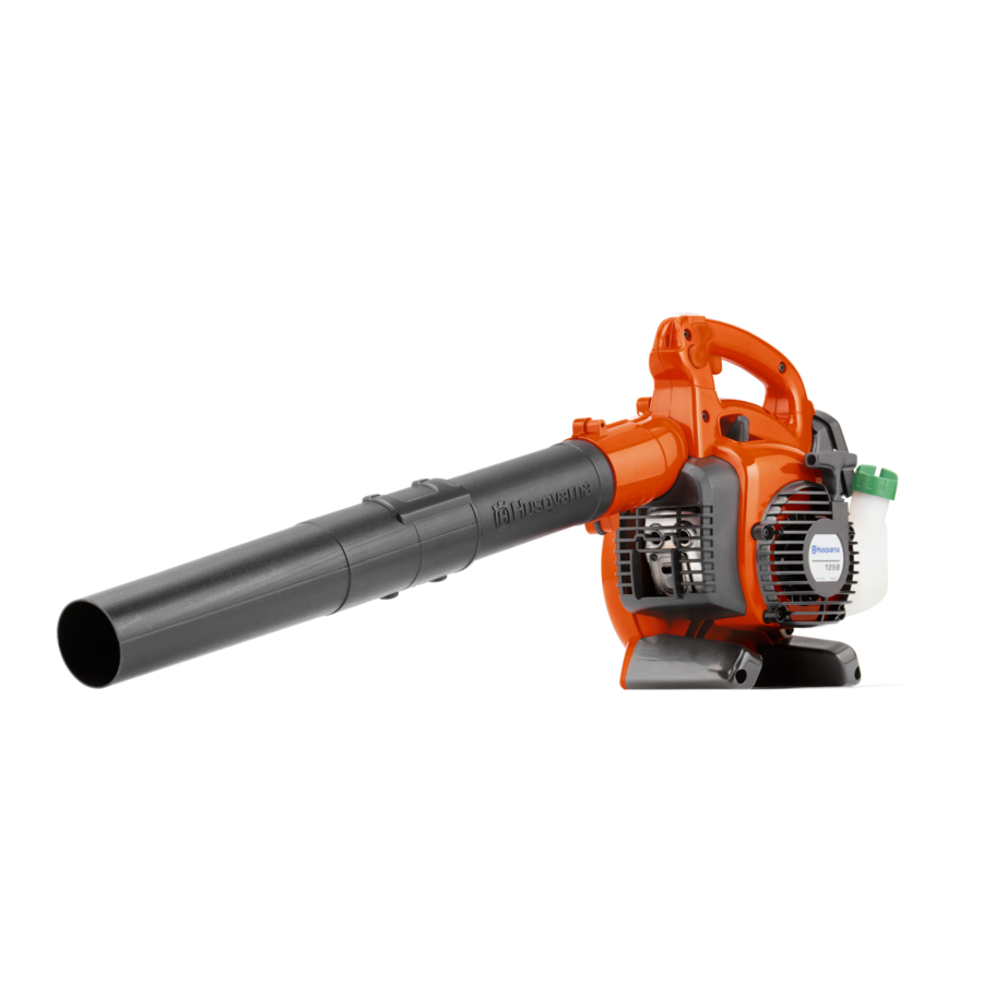
Husqvarna 125B, 125BX-Series, 125BVX-Series Operator's Manual
Husqvarna blower operator's manual
Hide thumbs
Also See for 125B, 125BX-Series, 125BVX-Series:
- Operator's manual (336 pages) ,
- Operator's manual (40 pages) ,
- Operator's manual (67 pages)
Table of Contents
Advertisement
Advertisement
Table of Contents

Related Manuals for Husqvarna 125B, 125BX-Series, 125BVX-Series


Summary of Contents for Husqvarna 125B, 125BX-Series, 125BVX-Series
- Page 1 EN FR ES...
-
Page 2: Table Of Contents
....545133423 Rev. 4 9/6/07 Note the following before starting: Husqvarna AB has a policy of continuous product development and therefore reserves the right to modify the design and appearance of products without prior notice. -
Page 3: Key To Symbols
WARNING! Make sure that the inlet cover is locked in the closed position or that the vacuum tube is mount- ed on the blower. Never touch the impeller un- less the unit is off, the impeller has stopped moving and the spark plug is disconnected. -
Page 4: Safety Instructions
S Stop the engine before fitting or disman- tling accessories or other components. S Never operate the blower if any of the guards are missing. S Never operate the blower in poorly venti- lated spaces where exhaust fumes might otherwise be inhaled. - Page 5 S Do not operate the blower while standing on a ladder or a stand. Other safety measures S Operate the blower only at reasonable hours, i.e.
-
Page 6: Blower Overview & Parts List
13. Fan impeller 14. Standard nozzle 15. High velocity nozzle (125B and 125BV X- -SERIES X- -SERIES 16. Blower tube 17. Tube clamp bolt 18. Tube clamp nut 19. Muffler 20. Ground wire 21. Starter handle 22. Starter device 23. Carburetor adjustment screws 24. - Page 7 DESCRIPTION Accessories (125B and 125BV X- - SERIES X- - SERIES 21. Vacuum device with collection components consisting of items 22- -26 below 22. Collection bag tube 23. Collection bag 24. Vacuum tube in two sections 25. Screw 26. Shoulder strap 545133423 Rev.
- Page 8 S To avoid causing damage to the unit, DO NOT attempt to use the variable speed control during starting or during vacuum use. Fan housing S The blower fan housing (E) and the fan impeller (F) provide high performance air discharge. English--- 8...
- Page 9 (see the gen- eral description of the blower on page 6). S The blower tube (K) has a pegged slot mounting system to the unit. To install or remove the blower tube (or collection bag...
-
Page 10: Adjusting The Carburetor
DESCRIPTION Choke S The choke (Q) is located below the air filter cover and should be used every time the engine is cold- -started. 545133423 Rev. 4 9/6/07 Adjusting the carburetor NOT FOR ALL MODELS S There are three adjusting screws (R) for adjusting the carburetor: S Low speed jet S High speed jet... -
Page 11: Fuel Handling
HUSQVARNA two- -stroke oil, which is specially formulated for our two- -stroke engines. Mixture 1:50 (2%). S If HUSQVARNA two- -stroke oil is not avail- able, you may use another two-stroke oil of good quality that is intended for air cooled engines. -
Page 12: Starting And Stopping
S Ensure that the fuel is well mixed by shak- ing the container before filling the tank. Starting and stopping WARNING: Never start the blower if the inlet cover is not closed, is damaged or cannot be closed (except if the vacuum tube is fitted). -
Page 13: Using The Blower
), the tube clamp X- -SERIES bolt must be removed. Align slot in the blower air outlet with the raised rib on the tube and insert tube until the holes in the tube and housing align. Re- -insert the tube clamp bolt and tighten. - Page 14 (about 3 inches/7 cm). Permanently as- semble the two tubes together with the supplied screw. 4. Open the cover on the side of the blower by using a screwdriver to pry up under the edge of the cover on the side opposite the hinge (indicated by arrow on inlet cover).
- Page 15 WARNING: Do not operate the blower while standing on a ladder or a stand. Start the blower as described in the Starting and Stopping section. Work according to the following instructions: 1. Do not vacuum large solid objects that can damage the fan, such as wood, cans (tins) or lengths of string or ribbon.
-
Page 16: Maintenance
Disconnect the spark plug before perform- ing maintenance, except carburetor adjust- ments. Carburetor Your Husqvarna product has been designed and manufactured to specifications that re- duce harmful emissions. After the engine has used 8- -10 tanks of fuel, the engine will be run- -in. -
Page 17: Air Filter
Clean the cooling system by brushing once a week, or more often, if necessary. A dirty or blocked cooling system will cause the blower to overheat and this will damage the cylinder and piston. 545133423 Rev. 4 9/6/07 Air filter... -
Page 18: Spark Plug
Maintenance schedule Below you will find some general mainte- nance instructions. Daily maintenance S Clean the exterior surfaces of the blower. S Check that the variable speed control and the throttle trigger function in a safe man- ner. Replace damaged parts. -
Page 19: Technical Data
Electrode gap, mm Fuel and lubrication system Manufacturer/type of carburetor Fuel tank capacity, liter Weight Weight, without fuel but with blower tube and standard nozzle fitted, kg Noise emissions (see note 1) Sound power level, measured dB(A) Sound power level, guaranteed L... -
Page 20: Declaration Of Conformity
DECLARATION OF CONFORMITY EC Declaration of Conformity (Only applies to Europe) We, Husqvarna Outdoor Products Italia, S.p.A., Valmadrera, Italy. Tel: +39- -0341- -203211, declare that the blower models Husqvarna 125B, 125B serial numbers 2007- -151N00001 and onwards (the year is clearly stated on the rating plate, followed by the serial number), comply with the requirements of the COUNCIL’S...