Table of Contents
Advertisement
Installer:
Leave this manual
with homeowner.
Homelink
is a registered trademark of
®
Johnson Controls Technology Company.
Car2U
®
is a registered trademark of
Lear Corporation.
© The Genie Company 2010. X900-786
PN# 37026500123, 2/26/2010 REV.1
A L W AY S AT Y O U R C O M M A N D
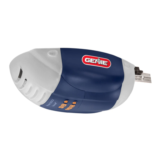
Models 2022/2024/2042
Includes: 2-Bulb Light System
Wall Console
Includes INTELLICODE
Safe-T-Beam
System must be installed to close door.
®
For use only with sectional doors.
Homelink
and Car2U
®
For Answers and Assistance:
1.800.354.3643
or visit www.geniecompany.com
SAVE THIS MANUAL FOR FUTURE REFERENCE
GARAGE DOOR OPENERS
Remote Control
®
compatible
®
Advertisement
Table of Contents
Troubleshooting

Related Manuals for Genie 2024


Summary of Contents for Genie 2024
- Page 1 Car2U ® is a registered trademark of Lear Corporation. © The Genie Company 2010. X900-786 PN# 37026500123, 2/26/2010 REV.1 A L W AY S AT Y O U R C O M M A N D Models 2022/2024/2042 Includes: 2-Bulb Light System...
-
Page 2: Safety Information
If you have questions or do NOT understand the information presented, contact The Genie Company or an authorized Genie The safety alert symbol and following signal words DANGER, WARNING, and CAUTION are used throughout this manual to call attention to and identify different levels of hazard and special instructions. -
Page 3: Table Of Contents
TABLE OF CONTENTS SECTION ......... PAGE SAFETY INFORMATION . -
Page 4: Pre-Installation Check List
They are as follows: The Genie Company recommends that you read and fully understand all information and instructions contained herein before choosing a "Do-it-yourself" installation. Any questions should be directed to The Genie Company or an authorized Genie ( The issue numbers below refer to the circled numbers in the illustrations on page 5. - Page 5 TYPICAL SECTIONAL DOOR INSTALLATION Pg. 19 TYPICAL SUPPORT BRACKET (NOT PROVIDED) POWER CORD (APPROX. 45 IN.) TO 120V GROUNDED OUTLET EXTENSION SPRING TORSION SPRING NOTE: This opener is designed for use with SECTIONAL doors only. FOR HELP-1.800.354.3643 OR WWW.GENIECOMPANY.COM Pg. 13 Pg.
-
Page 6: Recommended Tools
RECOMMENDED TOOLS Drill Safety Glasses Step ladder PARTS IDENTIFICATION - Safety Brochures Safe-T-Beam Safe-T-Beam ® Source with wire with wire (Green LED) (Red LED) Safe-T-Beam ® Source/Sensor Bracket Door Arm Pro Rail (Chain) Section Pro Rail (Belt) Section FOR HELP-1.800.354.3643 OR WWW.GENIECOMPANY.COM Pencil 3/16"... - Page 7 FASTENERS - Shown Full size (See Parts List below for full description.) BAG NO. DESCRIPTION RAIL SECTION CLAMP RAIL CLAMP BOLT – 5/16 -18 x 5/8'' HEX FLANGE NUT – 5/16 -18 BOLT – 5/16 -18 x 1/2'' CLEVIS PIN, LONG – 5/16" x 3" COTTER PIN HEADER BRACKET LAG SCREW –...
-
Page 8: Key Illustrations
1-PIECE RAIL HARDWARE ASSEMBLED VIEW CHAIN IN G In ju m ad ri o us t s an H IG ts m to ol m en ju st g pr Tensioner us in rs on ic e se rv Clevis Pin, Long Header &... -
Page 9: Safety Installation Information
1. READ AND FOLLOW ALL SAFETY, INSTALLATION AND OPERATION INSTRUCTIONS. questions or do not understand an instruction, call The Genie Company or an authorized Genie 2. Install only on a properly balanced sectional garage door. An improperly balanced door could cause severe injury. - Page 10 Rail Assembly for CHAIN DRIVE OPENER NOTE: For split rail clamps, nuts, and bolts locate Bag 0 from Box 1. 3. Remove the two rail sections that are not connected to the chain and place them on floor (Fig. 1-2, A). 4.
- Page 11 POWER HEAD & RAIL ASSEMBLY Assembly for CHAIN DRIVE OPENER NOTE: Handle carefully! Drive chain can slide out of rail. NOTE: For power head and rail assembly locate Bag 1 from Box 1. NOTE: Copy serial number from power head frame and record it on warranty page.
-
Page 12: Opener Installation
OPENER INSTALLATION HEADER AND DOOR MOUNTING BRACKETS: WARNING Header bracket must be fastened to garage framing. Do NOT fasten to drywall, particle board, plaster or other such materials. 1. Finding header bracket mounting location. • Close garage door. – Use a pencil and level. a) Mark center of garage door (one-half overall width) on the wall with 6"... - Page 13 MOUNTING THE OPENER: 1. Getting started. • Position assembled rail on wall next to header bracket (Fig. 2-4). – Place material on floor under power head to protect from scratching. (A box, stool, or similar device may be needed to clear a torsion spring.) NOTE: For header bracket pins locate Bag 2 from Box 1.
- Page 14 Contact door manufacturer or distributor for a bracing kit. The Genie Company is not responsible for damage caused due to improperly braced door. NOTE: For door bracket and bolts locate Bag 4 from Box 2.
-
Page 15: Wall Control Installation
WALL CONTROL INSTALLATION WARNING Verify there is NO power to the opener before installing Wall Control wires and Wall Control. CAUTION Staples which are too tight can cut or pinch wires. Cut or pinched wires can cause the Wall Control to stop working. - Page 16 3. Securely fasten wires. • Securely fasten wires to ceiling and wall using insulated staples provided. – Use insulated staples. – Staples should be snug only. • If rear cover is attached to power head, remove it. • On power head: –...
-
Page 17: Safe-T-Beam System Installation
– If not: a) Mounting bracket extensions are available through an authorized Genie b) Blocks of wood, etc. may be substituted for extensions. • Locate top of bracket on your mark (Fig. 4-2). - Page 18 3b. Wiring (pre-wired). • Route wire from wall to Safe-T-Beam (Fig. 4-5b). • Splice pre-wiring to shortened sensor wire, match wire pairs dash-to-dash (striped-to- striped) and plain-to-plain (white-to-white). - Trim sensor wire to approximately one foot (1 ft) from sensor. - Split and strip ends of sensor wires and pre-wired wires (Fig.
-
Page 19: Connecting To Power
• Wires inside the power head must be at least 6" in length. • Replace motor cover and rear cover and re-energize the circuit. NOTE: The Genie Company is not responsible for charges resulting from work performed by an independent electrician. WITH POWER SUPPLIED: Check Safe-T-Beam ®... -
Page 20: Limit Switches & Force Adjustment
DOOR LIMITS WARNING • Severe injury or death can result if the door closing force is set too high. • Never increase the door closing force above the minimum required to move the door. • Never adjust force to compensate for a sticking or binding door. -
Page 21: Keyed Emergency Release
CARRIAGE LOCK The Carriage Lock can be manually engaged or disengaged. • To disengage Carriage Lock – Pull handle downward opener power head. • To engage Carriage Lock – Pull handle towards door. KEYED EMERGENCY RELEASE (PURCHASED SEPARATELY) Obtain standard emergency release kit and remove S-hook from the cable end that attaches to the opener carriage. -
Page 22: Contact Reverse Test
UP/DOWN FORCE 1. By turning the "Close Force Control" wise, the DOWN force can be increased. By turning the "Close Force Control" clockwise, the DOWN force can be decreased. Set the DOWN force level at the minimum force required to close door without reversing. 2. -
Page 23: Programming Remote Controls
PROGRAMMING REMOTE CONTROLS WARNING A moving door can cause serious injury or death. 1. Keep people clear of opening while door is moving. 2. Do NOT allow children to play with opener, including Wall Control, remote control, or Wireless Keypad. 3. -
Page 24: Battery/Visor Clip Installation
REMOTE CONTROL 1. Battery replacement. • To open, gently push straight out on battery cover lock tab as shown. (Fig. 8-1). • Slide open battery cover. – Remove old battery. • Make sure new battery is facing proper direction (Match battery polarity with symbols inside battery housing) (Fig. -
Page 25: Safety Instructions
Have a trained door system technician make repairs to cables, spring assemblies, and other hardware. SAVE THESE INSTRUCTIONS. If you have any questions, please do not hesitate to contact Genie MAINTENANCE WARNING •... -
Page 26: Wiring Diagram
Opener circuit wiring diagram. This wiring diagram is for reference only. Schéma de câblage de l’ouvreur. Ce schéma de câblage est indiqué à titre de référence uniquement. WARNING ADVERTENCIA AVERTISSEMENT POWER CORD CORDON DE SECTEUR CABLE ELÉCTRICO TERMINAL BLOCK BORNE BLOQUE DE TERMINALES WHITE BLANC... -
Page 27: Troubleshooting Guide - Opener
System from the opener and contact an authorized ® Dealer or The Genie Company at 1-800-35-GENIE. ® Dealer or a trained door system technician, or contact The Genie ® Dealer or a trained door system technician, or contact The Genie ). Door opener will NOT run more... -
Page 28: Troubleshooting Guide - Power Head Led
• Set DOWN LIMIT programming • Check for obstruction, remove • Check for obstruction, remove. – Check door spring (See section – Contact The Genie Company at 1-800-35-GENIE • Set UP LIMIT programming • Check power head wiring, check connections, –... -
Page 29: Transmitter Compliance Statement
TRANSMITTER COMPLIANCE STATEMENT Transmitters comply with all United States and Canadian legal requirements as of the date of manufacture. No warranty is made that they comply with all legal requirements of any other jurisdiction. If transmitters are to be used in another country, the importer must determine compliance with any local laws and regulations which may differ from United States and Canadian requirements prior to use. -
Page 30: Warranty
Models 2022/2024/2042 GMI Holdings, Inc. d/b/a The Genie Company ("Seller") warrants to the original purchaser of the below identified opener, Model 2022/2024/2042 (“Product”), subject to all of the terms and conditions hereof, that the Product and all components thereof will be free from defects in materials and workmanship for the following period(s) of time, measured from the date of purchase: MOTOR - Seller warrants the motor for a period of TEN (10) YEARS. - Page 31 This page left blank.
- Page 32 This page left blank.
- Page 33 This page left blank.
- Page 34 Contacter 1-800-35-GENIE. Company Genie Contacter (voir chaîne tension section (Voir motorisée. dans l'emplacement 1-800-35-GENIE. Company Genie Contacter câblage. et/ou bouton remplacer Réparer fils. court-circuiter l’isolant traverser peuvent câblage. bouton section reprogrammer limites d'obstruction. présence capteur. source l'alignement réparer...
- Page 35 Comuníquese 1-800-35-GENIE Genie Compañía Comuníquese sección (Vea cadena tensión Ajuste sección (Vea control. caja conector inverso alambre Colocación 1-800-35-GENIE Genie Compañía Comuníquese alambrado. pulsador botón cambie Repare cables. cortocircuito hacer aislamiento cortar pueden grapas alambrado.
- Page 36 (voir équilibrée porte fils court-circuiter télécommande codes 1-800-35-GENIE garage, porte ressorts 1-800-35-GENIE garage, porte ressorts porte lubrifiés bien fils. court-circuiter réparation fermée complètement bouton Maintenant commande effectuer mauvais obstruction toute section (voir porte pile s'allume garage porte télécommande section section (Voir récepteur.
- Page 37 (Vea CERRAR control códigos todos 1-800-35-GENIE Genie Compañía entrenado técnico Genie garaje puerta herraje sección 1-800-35-GENIE Genie Compañía entrenado técnico Genie garaje puerta herraje sección sección mantenimiento) correctamente bien, estén...
- Page 38 (voir l'alignement Vérifier clignote. rouge diode Safe-T-Beam Systèmes ® AGRÉÉ. GENIE REVENDEUR COMPANY GENIE CONTACTER pas, toujours fonctionne l’ouvreur CONTACT). INVERSION section (voir colombe avec contact arrière repart porte murale. commande bouton l’aide à porte Fermer garage. porte l’ouverture centre sol.
- Page 39 suivant: numéro INSTRUCTIONS. quincaillerie. autre technicien à Demander mort. porte propriétaire manuel Consulter descendre faire peuvent brisés Utiliser fermée. porte lorsque graves blessures entraîner peut limite force réglé avoir Après objet d’un contact OUVERTE. soit porte jusqu'à objet télécommandes Garder porte.
- Page 40 électrique. prise dans d’alimentation cordon Brancher puissance. arrière l'objectif pour Répétition 9-2). (Fig. lentille fentes dans engagées totalement sont languettes S'assurer motorisée. tête lentille Placer lentille dans correspondantes fentes motorisée tête lampe lentille languettes aligner garage, porte près plus puissance principale l'extrémité...
- Page 41 reprogrammée. été n’aurait autre toute disparue télécommande perçus signaux plus reconnaître l’ouvreur Votre manuel. dans stipulées instructions selon possession votre toujours sont celles télécommandes nouvelles Programmer s'éteigne. clignotante rouge jusqu'à secondes pendant motorisée tête programmation bouton Appuyer mémoire. Effacer VOLÉE PERDUE TÉLÉCOMMANDE local.
- Page 42 inverse. sens dans déplacer doit porte bouton. nouveau à Appuyer s’arrête. porte bouton. nouveau à Appuyer déplace. porte commande. bouton fois Appuyer Fonctionnement. bouton. seul à télécommande programmation étapes avec boutons chacun Programmer bouton. chaque boutons. plusieurs à télécommande Programmation l'usage.
- Page 43 nécessaire. fois plusieurs Répéter Retester. antihoraire). sens dans tourner fermeture force réduire légèrement faut arrière, repart mais s’arrête porte – colombe. avec contact d’entrer avant fermeture course limite atteint avoir devrait Elle fermeture. limite pour programmée porte Vérifier – correctement. s’inverse porte Réglage...
- Page 44 garage. porte ouvrir à continuez clé Relâchez po). à garage porte tout maintenez-la clé tourner fente. dans clé Insérez clé. déverrouillage d'utilisation Instructions secours. déverrouillage nécessaire fonctionnement standard. déverrouillage nécessaire restantes d'installation instructions secours. déverrouillage défaillance engendrera l'ouvre-porte chariot secours déverrouillage câble inapproprié...
- Page 45 mémorisée. ouverte position deux vert clignote L'indicateur secondes. boutonpendant relâcher d'ouverture limite définition bouton appuyer souhaitée, position dans trouve porte Lorsque BAS. vers légèrement porte déplacer pour fermeture course limite bouton utiliser également pouvez Vous incréments. petits porte déplacer pour d'ouverture course limite...
- Page 46 fermeture. mouvement pendant murale commande fermeture bouton relâchez vous ouverte totalement position revenir pour automatiquement course inverse porte problème. solutionner d'abord devez vous informant vous pause) ☼☼ pause ☼☼ (Modèle: fois deux clignotera vert sera motorisé, tête s'allume L'indicateur fermée. totalement position atteigne...
- Page 47 tension. sous circuit remettre arrière capot moteur capot Replacer minimum. être doit motorisée tête l’intérieur à fils longueur agréés câbles à écrous uniquement Utiliser vert. à terre à noir/mise à blanc/noir à Blanc diamètre trou avec motorisée têtes à permanent câblage Connecter 5-3).
- Page 48 BRANCHER! 19). page électrique l’alimentation à connexions suivant effectuée être doit Safe-T-Beam ® l’alignement vérification REMARQUE: moment. (lampe) blanc couvercle installer 4-9). (Fig. motorisée tête clips couleur même couvercle arrière. couvercle Installer borne. trou dans place rester doit fil. légèrement tirant blocage Confirmer...
- Page 49 excès. avec agrafes serrer isolées. agrafes Utiliser suivante). page (Fig. mesure à plafond fils fixer Bien 4-5). (Fig. indiquées méthodes l’une selon motorisée tête jusqu'à Safe-T-Beam ® capteurs depuis Acheminer pré-câblage). (Sans Câblage 4-3). (Fig. enclenchement jusqu’à support languette capteur source/le Glisser d’ombre.
- Page 50 REMARQUE: 4-2). (Fig. l’aide à fixer 4-2). (Fig. marque votre parenthèse dessus d'extensions. servir peuvent etc. bois blocs agréé. Genie revendeur d'un auprès disponibles sont montage support extensions contraire: porte. ferrure autre toute rails porte, dépasse languette pour suffisamment...
- Page 51 porte activation après minutes LOIN allume tourne l'interruption L'Énergie-Épargnant garage l'intérieur porte d'ouvreur lumières Commande indépendante légère Commande garage l'intérieur porte fermez Ouvrez – bouton "Ouvrez-vous/Fin" porte Commande normalement travailler commandes à permet OUVREZ – fermée complètement soit porte après commandes désactive SERRURE...
- Page 52 (négative). borne à blanc (positive). borne à rayé murale. commande bouton commande carte 3-2). fils l’extrémité dénuder Séparer motorisée. à murale commande Acheminer 3-1). (Fig. susmentionnées instructions selon procédant murale commande montage pour pratique emplacement Sélectionner pré-câblé). Câblage (négative). borne à...
- Page 53 Repérage Boîte localiser boulons, porte support Pour REMARQUE: inadéquat. porte renforcement d’un résulter pourraient dommages responsable n’est Company Genie renforcement. propos à porte distributeur fabricant Contacter porte. l’ouvreur l’installation avant renforcées correctement être doivent tôle verre fibre léger,...
- Page 54 L'OUVRE-PORTE! ENCORE BRANCHEZ serrés. bien sont situés écrous boulons Vérifier rail. motorisee tete section aucune avec contacte n'entre porte Assurez porte fermez ouvrez Soigneusement motorisée. écrous boulons serrer niveau. dessous légèrement motorisée tête niveau à Être course. haut plus point porte passer doit...
- Page 55 2-3). (Fig. (fournies) tire-fond l’aide à linteau support Fixer – trou. repères chacun 3/16 guide trous Percer mur. trous emplacements pour trait Tracer finale. hauteur ligne inférieur Bord – verticale. ligne centre Placer – qu'illustré. support Placer 2-3). (Fig. linteau support Placer linteau.
- Page 56 INSTALLATION. section Commencer assemblés rail motorisée tête 1-8). (Fig. l'installation poursuivre MAINTENANT garage porte désactiver câbles et/ou cordes enlever cas, n'est porte. verrouil- désactivé porte), câbles (PAS câbles tous cordes toutes retiré avoir déjà devez Vous courroie. excessivement tendez 1-7). (Fig.
- Page 57 écrous. boulons bien serrez rail, sections montées rail à pinces deux fois écrous. boulons l'aide à rail section joints rail à pinces deux Fixez 1-4). & (Fig. tendeur poulie autour l'enroulant courroie tirant rail sections trois Alignez pi). environ s'étendre doivent rail courroie...
- Page 58 ultérieure. utilisation pour boîte Enlever ultérieurement). utilisée sera (elle moteur motorisée tête référence servant contenus composants illustrant étiquette trouve chaque couvercle l'intérieur À montage. tâches organisés sont pièces contiennent boîtes 1-1). placer (étiquetées internes boîtes trois soigneusement Déballer boîtes. moins dans emballés pièces...
- Page 59 Genie à Demander blessures. graves porte équilibrée. correctement garage porte uniquement local). votre Company Genie contacter ci-incluses, instructions comprenez questions...
- Page 60 Courroie Correa Knob Release déclenchement courroie avec Rail desenganche Correa Riel trolley motorisée Tête trole control Caja d’alimentation Courroie Correa chariot Glissière carro Deslizador ceinture correa Abrazadera motorisée Tête chariot control Caja d’alimentation REV. 02/26/2010 37026500123 Courroie Correa central Rail central Riel rail...
- Page 61 hexagonale hexagonal po-18 5/16 épaulement à Boulon 1" 5/16 Cáncamo hexagonale hexagonal 5/16-18 hexagonale tête à Boulon 1/2" 5/16 po-18 5/16 hexagonal cabeza Perno 5/16 5/16-18 hexagonale 3/4" 5/16 hexagonal po-20 autotaraudeuse 3/4" perforación Tornillo 3/4" 5/16" fendue Goupille patas Chaveta 5/16 long...
- Page 62 moteur l'ensemble courroie) (avec (correa) riel cabeza moteur l'ensemble chaîne) (avec (cadena) riel cabeza rail centrale Section riel rail section Dernière riel rail section Pince riel sección Grapa boutons trois à Télécommande botones remoto Control coinçage risque d’avertissement Étiquette atrapamiento advertencia Rótulo ©1999...
- Page 63 avec uniquement l’ouvreur Utiliser matériel corporelles blessures AVERTISSEMENT SECTION À PORTE SECCIONES PUERTA Pág. SAFE-T-BEAM ® SAFE-T-BEAM ® 17-18 Pág. Pág. RENFORTS RIOSTRAS LINTEAU SUPPORT SUPPLÉMENTAIRE MONTAGE PLANCHE TRAVESAÑO SOPORTE MONTAJE TABLERO AGREGADO 12-13 Pág. REV. 02/26/2010 37026500123 section. à portes d’endommagement secciones.
- Page 64 à reporter motorisée tête à trouver doit être doit 110-120 section. l’ouvreur Utiliser corporelles blessures AVERTISSEMENT page illustrations agréé. Genie revendeur l'installation. à vous-même informations toutes suivantes: d’abord devez vous d’l’ouvreur, Toutefois, neuf. installer sections. devez vous l’installation, PRÉ-INSTALLATION REV.
- Page 65 GENERADOR EXTENSIÓN! ADVERTENCIA Sección (Refiérase control, caja pies tomacorriente voltios. corriente suministro solamente abridor este personas lesiones ADVERTENCIA página ilustraciones Genie Compañía bricolaje "de instalación información toda plenamente pre-instalación nuevo; existente SECCIONES. bricolaje." mismo PRE-INSTALACIÓN REV. 02/26/2010 37026500123 para (GER-2)
- Page 66 incluse. command avec installé être DOIT *l’ouvreur incluye. control instalarse DEBE abridor section à reporter porte. manuelle- fermer ouvrir pour urgence toute courant panne Vous l’ouvreur. porte manuellement d’urgence. manuel Déclenchement minutes. après automatiquement s’éteint actionnée porte lorsque soir. sécuritaires plus sorties rendre...
- Page 67 Genie ® questions avez vous appliquent. exigent autres celle sécurité votre où mesure Dans électriques. moteurs presentada, información entiende usuario...
- Page 68 Incluye ® Intellicode télécommande Inclut ® pared control doble bombillo murale bouton système GARAJE PUERTAS OPERADOR GARAGE OUVRE-PORTE 2022/2024/2042 visitez Company Company Technology FUTURA Pout ULTERIEURE RÉFÉRENCE dueño. propriétaire. Para (Safe-T-Beam seguridad luminoso ® être doit Safe-T-Beam système ®...