Table of Contents
Advertisement
Advertisement
Table of Contents

Related Manuals for Mitsubishi Electric CITY MULTI P500YMF-C


Summary of Contents for Mitsubishi Electric CITY MULTI P500YMF-C
- Page 1 AIR CONDITIONERS CITY MULTI PURY-P400, P500YMF-C Models Service Handbook...
-
Page 3: Table Of Contents
Contents PRECAUTIONS FOR DEVICES THAT USE R407C REFRIGERANT ..[1] Storage of Piping Material ..............4 [2] Piping Machining ................5 [3] Brazing ....................6 [4] Airtightness Test ................7 [5] Vacuuming ..................7 [6] Charging of Refrigerant ..............8 [7] Dryer .................... -
Page 4: Safety Precautions
• Do not reconstruct or change the settings of the protection devices. - If the pressure switch, thermal switch, or other protection device is shorted and operated forcibly, or parts other than those specified by Mitsubishi Electric are used, fire or explosion may result. –2–... -
Page 5: Precautions For Devices That Use R407C Refrigerant
1 1 1 1 1 PRECAUTIONS FOR DEVICES THAT USE R407C REFRIGERANT Caution Do not use the existing refrigerant piping. Use a vacuum pump with a reverse flow check valve. • The vacuum pump oil may flow back into the refriger- •... -
Page 6: Storage Of Piping Material
[1] Storage of Piping Material (1) Storage location Store the pipes to be used indoors. (Warehouse at site or owner’s warehouse) Storing them outdoors may cause dirt, waste, or water to infiltrate. (2) Pipe sealing before storage Both ends of the pipes should be sealed until immediately before brazing. Wrap elbows and T’s in plastic bags for storage. -
Page 7: Piping Machining
[2] Piping Machining Use ester oil, ether oil or alkylbenzene (small amount) as the refrigerator oil to coat flange connections. Use only the necessary minimum quantity of oil ! Reason : 1. The refrigerator oil used for the equipment is highly hygroscopic and may introduce water inside. Notes : •... -
Page 8: Brazing
[3] Brazing No changes from the conventional method, but special care is required so that foreign matter (ie. oxide scale, water, dirt, etc.) does not enter the refrigerant circuit. Example : Inner state of brazed section When non-oxide brazing was not used When non-oxide brazing was used Items to be strictly observed : 1. -
Page 9: Airtightness Test
[4] Airtightness Test No changes from the conventional method. Note that a refrigerant leakage detector for R22 cannot detect R407C leakage. Halide torch R22 leakage detector Items to be strictly observed : 1. Pressurize the equipment with nitrogen up to the design pressure and then judge the equipment’s airtightness, taking temperature variations into account. -
Page 10: Charging Of Refrigerant
[6] Charging of Refrigerant R407C must be in a liquid state when charging, because it is a non-azeotropic refrigerant. For a cylinder with a syphon attached For a cylinder without a syphon attached Cylin- Cylin- Cylinder color identification R407C-Gray Charged with liquid refrigerant R410A-Pink Valve Valve... -
Page 11: Component Of Equipment
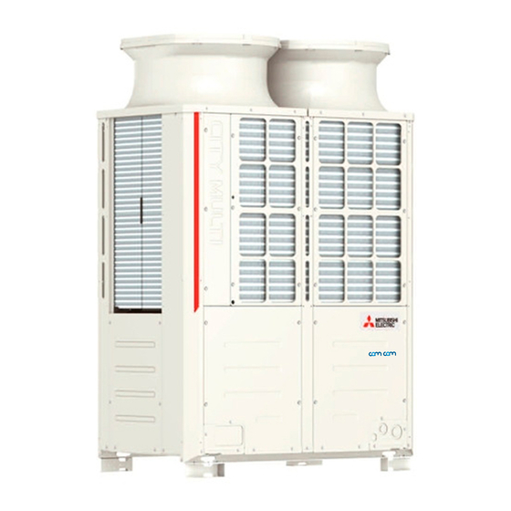
2 2 2 2 2 COMPONENT OF EQUIPMENT [1] Appearance of Components Outdoor unit • PURY-P400·500YMF-C Propeller fan Fan motor Propeller fan Fan motor Heat exchanger(rear) Heat exchanger(front) Compressor Control box P400 TYPE P500 TYPE SV block 1 CS circuit 4–way valve Accumulator 4–way... - Page 12 Controller Box RELAY board FANCON board (for MF3) Choke coil (L2) MAIN board INV board Magnetic contactor (52C2) SNB board Diode stack (DS) FANCON board (for MF2) G/A board Inteligent Power Overload relay (51C2) Module (IPM) Y-C board Magnetic contactor Noise filter Magnetic contactor (52C1) Capacitor (C2, C3)
- Page 13 MAIN board • PUHY / PURY CNVCC4 Power source CNTR CNFC1 for control(5V) CNS1 CNS2 CN40 CN41 CNVCC3 Power Source for control 1-2 30V 1-3 30V 4-6 12V 5-6 5V CN51 Indication distance 3-4 Compressor ON/OFF 3-5 Trouble CNRS3 Serial transmission to INV board CN3D CN3S...
- Page 14 INV board CNVDC DC-560V CN15V2 Power supply for IPM control CNVCC4 Power supply (5V) CNL2 Choke coil CNVCC2 Power supply 1-2 30V, 1-3 30V CN52C 4-6 12V, 5-6 5V Control for CNDR2 Out put to G/A board CNFAN Control CNTH for MF1 CNAC2 Power...
- Page 15 FANCON board CNPOW CNFAN CNFC2 G/A board CNDC1 CN15V1 CNIPM1 CNDR1 –13–...
- Page 16 SNB board Y-C board –14–...
- Page 17 BC controller CNTR CN12 CN02 Power M-NET supply transmission 1 EARTH CN03 –15–...
- Page 18 RELAY 10 board RELAY 4 board –16–...
-
Page 19: Refrigerant Circuit Diagram And Thermal Sensor
[2] Refrigerant Circuit Diagram and Thermal Sensor : Solenoid valve PURY-P400, 500YMF-C : Orifice : Capillary : Check valve : Thermal sensor : Strainer : Service port : Accumulator –17–... - Page 20 CMB-P108, 1010, 1013, 1016V-FA : Solenoid valve : Orifice : Capillary : Check valve : Thermal sensor : Strainer –18–...
- Page 21 CMB-P108V-FB : Solenoid valve : Orifice : Capillary : Check valve : Thermal sensor : Strainer –19–...
-
Page 22: Electrical Wiring Diagram
[3] Electrical Wiring Diagram PURY-P400·500YMF-C –20–... - Page 23 –21–...
- Page 24 –22–...
- Page 25 –23–...
-
Page 26: Standard Operation Data
[4] Standard Operation Data 1 Cooling operation Outdoor unit PURY-P400YMF-C PURY-P500YMF-C Items Indoor 27.0/19 27.0/19 Ambient temp. DB/WB Outdoor 35.0/24.0 35.0/24.0 Quantity Indoor unit Quantity in operation Model Main pipe Piping Branch pipe Total piping length Indoor unit fan notch Refrigerant volume 27.1... - Page 27 2 Heating operation Outdoor unit Items PURY-P400YMF-C PURY-P500YMF-C Indoor 20.0/- 20.0/- Ambient temp. DB/WB Outdoor 7.0/6.0 7.0/6.0 Quantity Indoor unit Quantity in operation Model Main pipe Piping Branch pipe Total piping length Indoor unit fan notch Refrigerant volume 27.1 29.2 Total current 25.6/24.3/23.4...
-
Page 28: Function Of Dip Sw And Rotary Sw
[5] Function of Dip SW and Rotary SW (1) Outdoor unit PURY-P400·500YMF-C. 1 Variable capacity unit MAIN board Function According to Switch Operation Switch Set Timing Switch Function When Off When On When Off When On SWU 1 ~ 2 Unit Address Setting Set on 51 ~ 100 with the rotary switch.*2 Before power is turned on. - Page 29 (2) Indoor unit DIP SW1, 3 Operation by SW Switch set timing Remarks Switch SW name Room temp. sensor position Indoor unit inlet Built in remote controller Clogged filter detect. None Provided Filter duration 100h 2500h Always ineffective for PKFY-P.VAM OA intake Ineffective Effective...
- Page 30 Setting of DIP SW4 Setting of DIP SW5 Model Circuit board used 220V 240V PMFY-P-VBM-A PLFY-P-VLMD-A – – – – PDFY-P20 ~ 80VM-A PLFY-P40 ~ 63VKM-A PLFY-P80 ~ 125VKM-A Phase control PCFY-P-VGM-A PKFY-P-VGM-A PKFY-P-VAM-A – – – – PEFY-P20 ~ 80VMM-A PFFY-P-VLEM-A, P-VLRM-A –...
-
Page 31: Test Run
3 3 3 3 3 TEST RUN [1] Before Test Run (1) Check points before test run Neither refrigerant leak nor loose power source/ transmission lines should be found. Confirm that the resistance between the power source terminal block and the ground exceeds 2M by measur- ing it with a DC 500 V megger. - Page 32 (3) Check points for test run when mounting options Built-in optional parts Content of test run Check point Result Release connector of pump circuit, Local remote controller displays code No. Mounting of drain check error detection by pouring water “2503”, and the mechanism stops. water lifting-up mechanism into drain pan water inlet.
- Page 33 (5) Check points for system structure In the case of the PURY-P400·500 YMF-C Check points from installation work to test run. Classification Portion Check item Trouble Instruction for selecting combination of outdoor unit, and Not operate. Installation indoor unit followed? (Maximum number of indoor units and piping which can be connected, connecting model name, and total capacity.)
- Page 34 CENTRALLY CONTROLLED 1Hr. CENTRALLY CONTROLLED 1Hr. ˚C ˚C ON OFF ON OFF D A I L Y D A I L Y AUTO OFF AUTO OFF CLOCK FILTER CLOCK FILTER CHECK REMAINDER CHECK REMAINDER CHECK MODE CHECK MODE TEST RUN TEST RUN STAND BY STAND BY...
-
Page 35: Test Run Method
[2] Test Run Method Operation procedure Turn on universal power supply at least 12 hours before starting Displaying “HO” on display panel for about two minutes Press TEST RUN button twice Displaying “TEST RUN’’ on display panel Press selection button Make sure that air is blowing out Press select button to change from cooling to heating operation, and vice versa... -
Page 36: Grouping Registration Of Indoor Units With M-Net Remote Controller
4 GROUPING REGISTRATION OF INDOOR UNITS WITH M-NET REMOTE CONTROLLER (1) Switch function • The switch operation to register with the remote controller is shown below: CENTRALLY CONTROLLED ˚C ON OFF D A I L Y AUTO OFF CLOCK FILTER CHECK REMAINDER CHECK MODE... - Page 37 (2) Attribute display of unit • At the group registration and the confirmation/deletion of registration/connection information, the type (attribute) of the unit is displayed with two English characters. Display Type (Attribute) of unit/controller Indoor unit connectable to remote controller Outdoor unit BC controller (Master) BC controller (Slave) Local remote controller...
- Page 38 (3) Group registration of indoor unit Registration method • Group registration of indoor unit ................ 1 The indoor unit to be controlled by a remote controller is registered on the remote controller. [Registration procedure] 1 With the remote controller under stopping or at the display of “HO”, continuously press the switch FILTER (A + B) at the same time for 2 seconds to change to the registration mode.
- Page 39 Method of retrieval/confirmation • Retrieval/confirmation of group registration information on indoor unit ....2 The address of the indoor unit being registered on the remote controller is displayed. [Operation procedure] 1 With the remote controller under stopping or at the display of “HO”, continuously press the switch (A FILTER + B) at the same time for 2 seconds to change to the registration mode.
- Page 40 • Registered (Alternative display) TEMP ON/OFF CLOCK ON OFF FILTER CHECK TEST PAR-F27MEA TIMER SET 1 + 2 (Alternative display) 1 Set the address 2 Press the switch for confirmation (E) * Same display will appear when the unit of “007” is not existing. •...
- Page 41 Deletion of information on address not existing • Deletion of information on address not existing ........... 5 This operation is to be conducted when “6607” error (No ACK error) is displayed on the remote controller caused by the miss setting at test run, or due to the old memory remained at the alteration/modification of group composition, and the address not existing will be deleted.
-
Page 42: Control
5 5 5 5 5 CONTROL [1] Control of Outdoor Unit [1]- 1 PURY-P400·500 YMF-C (1) Initial processing • When turning on power source, initial processing of microcomputer is given top priority. • During initial processing, control processing corresponding to operation signal is suspended. The control processing is resumed after initial processing is completed. - Page 43 • The operating temperature is 124 C (No. 1 compressor) or 115 C (No. 2 compressor). 4) Compressor frequency control 1 Ordinary control The ordinary control is performed after the following times have passed. • 30 seconds after the start of the compressor or 30 seconds after the completion of defrosting. •...
- Page 44 2) Bypass solenoid valves (SV1, SV4) [Both SV1 and SV4 are on (open)] SV4a Item ON for 4 minutes — At compressor is started — Compressor stopped during cool- ing or heating mode — After operation has been stopped ON for 3 minutes Normally ON During defrosting ((*1) in Fig below) During oil recovery operation...
- Page 45 (5) Oil return control (Electronic expansion valve (SLEV)) • The amount of opening of the oil-return LEV (SLEV) is determined as follows: in cooling, by the operating capacity of the No. 1 compressor and the ambient temperature; in heating, by the operating capacity of the No. 1 compressor. •...
- Page 46 5) Change in number of operating indoor units while defrosting • If the number of indoor units changes while the outdoor unit is defrosting, the defrosting operation continues. Once defrosting has ended, control for changing the number of units is performed. •...
- Page 47 (9) Outdoor unit heat exchanger capacity control 1) Control method • In order to stabilize the evaporation temperature during cooling and the high-pressure pressure during heating that are required in response to performance needs, the capacity of the outdoor heat exchanger is controlled by regulat- ing the fan volume of the outdoor unit by phase control and controlling the number of fans and by using the solenoid valves to vary the number of out door heat exchangers being used.
- Page 48 (11) Control at initial starting • When the ambient temperature is low (5 C or less in cooling and – 5 C or less in heating), initial starting will be performed if the unit is started within 4 hours of the power being turned on. •...
- Page 49 <Initial start control timing chart> End of initial operation mode minutes 30 minutes 10 minutes 5 minutes (Example 1) ON/OFF of No.1 compressor Note 1 ON/OFF of No.2 compressor Step 1 Step 2 Step 3 End of initial operation mode minutes minutes (Example 2)
- Page 50 (12) Emergency response operating mode The emergency operation mode is a mode in which the unit is run in an emergency to respond to the trouble when the compressors (No. 1, No. 2) break down, making it possible to carry out a abnormality reset using the remote control. 1) Starting the Emergency Operation Mode 1 Trouble occurs (Display the abnormality code root and abnormality code on the remote control).
-
Page 51: Control Of Bc Controller
[2] Control of BC Controller (1) Control of SVA, SVB and SVC SVA, SVB and SVC are turned on and off depending on connection mode. Mode Cooling Heating Stop Defrost Connection (2) Control of SVM1 (only FA type) SVM1 is turned on and off corresponding to operation mode. Operation mode Cooling-only Cooling-main... -
Page 52: Operation Flow Chart
[3] Operation Flow Chart (1) Outdoor unit Start Normal operations Breaker turned on Trouble observed Stop “HO” blinks on the remote controller Note : 1 Set indoor ad- dress No. to remote controller Operation command Oil return LEV, fully closed Operation mode Cooling-only, Heating-only,... - Page 53 (2) BC controller Start Normal operations Breaker turned on Trouble observed Stop Operation command 1. Operation mode judgement (cooling-only, heating-only, cooling/heating mixed) 2. Transmission to outdoor unit Receiving operation mode command from outdoor unit Note : 1 Error mode Error stop Cooling/heating mixed Operation mode Error code blinks on the...
- Page 54 (3) Indoor unit Start Normal operations Trouble observed Breaker turned on Stop Operation SW turned on Note :1 1. Protection function self-holding cancelled. 2. Indoor unit LEV fully closed. Note :2 Remove controller display extinguished Error mode Operation mode Error stop only for PURY Error code blinks on Heating...
- Page 55 (4) Cooling operation Cooling operation Normal operations 4-way valve OFF Test run Stop Indoor unit fan operations Test run start Thermostat ON 3-minute restart prevention 1. Inverter frequency control 1. Inverter output 0Hz 2. Indoor unit LEV, oil return LEV 2.
- Page 56 (5) Heating operation Normal operations Heating operation Defrosting operations Note : 1 Stop Note : 2 Test run Defrosting operation 4-way valve OFF 4-way valve ON Test run start 1. Indoor unit fan stop 2. Inverter defrost frequency control 3. Indoor unit LEV fully opened, oil return LEV fully closed 4.
- Page 57 (6) Dry operation Dry operations Normal operations Thermostat ON 4-way valve OFF Stop Test run start Note : 2 Thermostat ON Inlet temp. 18˚C Note : 1 1. Outdoor unit (Compressor) intermit- 1. Indoor unit fan stop tent operations 2. Inverter output 0Hz 2.
-
Page 58: List Of Major Component Functions
[4] List of Major Component Functions Code Name Product code Application Specification Inspection method (Function) 1 Adjustment of super heat of heat Electronic DC 12 V Perform a continuity check using a tester. expansion exchanger outlet port of indoor unit Amount of opening of the Conductivity among valve... - Page 59 Code Name Product code Application Specification Inspection method (Function) Thermistor = 15 k Resistance check Detects liquid level of refrigerant inside = 3460 accumulator using the differences 1/80 (Liquid level Rt = among TH2, TH3, TH4. detection) 15exp{3460( 273+t 1 Frequency control. 0 C: 15 k 2 Controls defrosting during heating.
- Page 60 Code Name Product code Application Specification Inspection method (Function) Solenoid Controls heat exchanger capacity of AC 220 to 240 V Conductivity test SV3~8 heat vallve outdoor unit. Close: conducting using tester. exchanger capacity Open : not conducting control Evaporation of liquid refrigerant inside AC 220 to 240 V SV6a MC2.
-
Page 61: Resistance Of Temperature Sensor
[5] Resistance of Temperature Sensor Thermistor for low temperature Thermistor R = 15k 3% (TH3 ~ 9) Thermistor R = 7.465k 2% (TH1, 10) = 15exp {3460 ( = 7.465exp {4057 ( 273+t 273+120 273+t 273+0 –20 –10 Temperature (˚C) Temperature (˚C) Thermistor R = 33k... -
Page 62: Refrigerant Amount Adjustment
6 6 6 6 6 REFRIGERANT AMOUNT ADJUSTMENT By clarifying the relationship between the refrigerant amount and operating characteristics for BgR2 Series, conduct service activities such as decision on the amount and adjustment of refrigerant on the market. [1] Operating Characteristics and Refrigerant Amount The followings are operating characteristics and refrigerant amount which draw special attention. - Page 63 At the time of shipping from the factory, the outdoor unit is charged with the amount of refrigerant shown in the following table, but since no extension piping is included, please carry out additional charging on-site. Outdoor Unit Model PURY-P400YMF-C PURY-P500YMF-C Refrigerant Charge Volume 20 kg 22 kg Calculation Formula Calculate the additional refrigerant volume by calculating the size of the extension liquid piping and its length (units: m).
-
Page 64: Refrigerant Volume Adjustment Mode Operation
[3] Refrigerant Volume Adjustment Mode Operation (1) Procedure Depending on the operating conditions, it may be necessary either to charge with supplementary refrigerant, or to drain out some, but if such a case arises, please follow the procedure given below. Switching the function select switch (SW2-4), located on the outdoor unit’s control board, ON starts refrigerant volume adjustment mode operation and the following operation occurs. - Page 65 (2) Refrigerant adjustment in Cooling season (Flow chart) In case of PURY-P400, 500YMF-C Adjustment starts. Start cooling operation of all indoor units in a test run mode. Note 1 Note 1) As the refrigerant volume can not be adjusted in the heating mode, retrieve the refrigerant, evacuate air and then fill the specified volume of refrigerant if it is necessary to adjust the refrigerant Has the...
- Page 66 (3) Refrigerant adjustment in heating season (Flow chart) In case of PURY-P400, 500YMF-C Start Adjustment Run all the indoor units in the heating condition in the test run mode. Note: 1 AL = 1 or 2 Note: 2 Note: 3 Is the AL = 2 Has the operating...
- Page 67 Note: 1 If there are any units which are not operating, it will cause refrigerant to accumulate, so by all means operate all the indoor units. Also, in order to prevent stable operation from being disrupted by the thermostat going OFF, set the trial operation mode.
-
Page 68: Troubleshooting
7 7 7 7 7 TROUBLESHOOTING [1] Principal Parts Pressure Sensor (1) Judging Failure 1) Check for failure by comparing the sensing pressure according to the high pressure/low pressure pressure sensor and the pressure gauge pressure. Turn on switches 1, 3, 5, 6 (High) and 2, 4, 5, 6 (Low) of the digital display select switch (SW1) as shown below, and the sensor pressure of the high pressure/low pressure sensors is displayed digitally by the light emitting diode LD1. - Page 69 2) SV22, SV32 (Full load/unload switching valve) (only P500YMF-C) 1 The No. 1 compressor is started first and operates for approximately 10 minutes and then the No. 2 compressor starts in the unload mode.
- Page 70 Solenoid Valves Block1 The refrigerant flow is as following figure. Hot gas (high pressured) flows in cooling mode and cool gas/liquid (low pressured) flows in heating mode. Please refer to the Refrigerant Circuit Diagram. And, ON/OFF of Solenoid valve is depends on the amount of running indoor units, ambient temperature and so on. So please check by LED Monitor Display.
- Page 71 Solenoid Valves Block2 Solenoid Valves Block 2 SV7 SV8 CV7b CV5b CV4b CV2b CV3b CV6b –69–...
- Page 72 Check Valves Block1 The refrigerant flow in the pipe 6, 7, 8 and 9 are depend on ON/OFF of the SV3, 4, 5 and 6. Please confirm by LED monitor display. You can open the cap of valve A, B and C, but 3 types of hexagon socket screw keys. The size is as follows. * Closed torque : A : 1.7kg·m (0.17N·m) B : 20kg·m (2.0N·m) C : 13kg·m (1.3N·m)
- Page 73 Check Valves Block2 CV5b CV4b CV2b CV3b CV6b Check Valves Block2 –71–...
- Page 74 Outdoor LEV The valve percentage opening changes in proportion to the number of pulses. (Connections between the outdoor unit’s MAIN board and SLEV, (PURY-P400·500YMF-C)) Pulse Signal Output and Valve Operation Output pulses change in the following orders when the Output states Output (phase) Valve is Closed 1 2 3 4 5 6 7 8 1...
- Page 75 Judgment methods and likely failure mode Caution: The specifications of the outdoor unit (outdoor LEV) and indoor unit (indoor LEV) differ. For this reason, there are cases where the treatment contents differ, so follow the treatment specified for the appropriate LEV as indicated in the right column.
- Page 76 Outdoor LEV (SLEV) Coil Removal Procedure (configuration) As shown in the figure, the outdoor LEV is made in such a way that the coils and the body can be separated. Body Coils Stopper Indentation for Stopper (12 places around the circumference) Lead Wires <Removing the Coils>...
- Page 77 Intelligent Power Module (IPM) Measure resistances between each terminal of IPM with tester, and use the results for troubleshooting. Specified resistance value is dependent on tester type to be used for resistance measurement, because diode inside IPM has non-linearity, thus difference of impedance and voltage in tester being influential. As the internal impedance of resistance range of analog tester equals to the center value of meter indication, the affect of internal impedance can be minimized if the tester having close center value of resistance range.
- Page 78 (2) Trouble and remedy of remote controller (In the case of MA remote controller) Phenomena Factors Check method and handling If pushing the remote 1) Power supply from transformers is not turned on in a) Check the MA remote control terminal control operation SW Indoor Unit.
- Page 79 Phenomena Factors When the remote 1) Power supply from the transformer is not available to the control board of BC controller. control SW is turned 1 The original power supply of the BC controller is not turned on. on, the indication 2 Removal of connectors (CN12, CN38, CNTR) on the control board of the BC controller.
- Page 80 Phenomena Factors “HO” indication on 1) The M-NET transmission power supply form the the remote controller outdoor unit is not supplied. is not lit, and the 1 The original power supply of Indoor Unit is not ON/OFF switch does turned on. 2 The connector on the controller board in Indoor not work.
- Page 81 (In the case of M-NET remote controller) Symptom Cause Checking method & countermeasure Despite pressing of 1) M-NET transmission power source is not supplied a) Check transmission terminal block of remote controller from outdoor unit. remote controller for voltage. 1 Main power source of outdoor unit is not ON/OFF switch, i) In case of 17 ~ 30V operation does not...
- Page 82 Symptom Cause “HO” display on re- (Without using MELANS) mote controller does 1) Outdoor unit address is set to “00” not disappear and 2) Erroneous address. ON/OFF switch is 1 Address setting of indoor unit to be coupled with remote controller incorrect. ineffective.
- Page 83 Symptom Cause Checking method & countermeasure “88” appears on re- [Generates at registration and confirmation] a) Confirm the address of unit to be mote controller at 1) Erroneous address of unit to be coupled. coupled. registration and b) Check the connection of transmission 2) Disconnection of transmission line of unit to be access remote coupled (No connection).
- Page 84 Transmission Power Circuit (30 V) Check Procedure If “ ” is not displayed by the remote control, investigate the points of the trouble by the following procedure and correct it. Check Item Judgment Response Disconnect the transmission line from TB3 DC24~30 V Check the transmission line for the following, and and check the TB3 voltage.
- Page 85 (3) Investigation of transmission wave shape/noise Control is performed by exchanging signals between outdoor unit, indoor unit and remote controller by M-NET transmission. If noise should enter into the transmission line, the normal transmission will be hindered causing erroneous operation. 1) Symptom caused by the noise entered into transmission line Cause Erroneous operation...
- Page 86 3) Checking and measures to be taken (a) Measures against noise Check the items below when noise can be confirmed on wave shape or the error code in the item 1) is generated. Items to be checked Measures to be taken 1 Wiring of transmission and power lines in Isolate transmission line from power line (5cm or more).
- Page 87 4) Treatment of Inverter and Compressor Troubles If the compressor does not work when error codes 4240, 4250, 4340 or 4350 are detected, determine the point of malfunction by following the steps in the LED monitor display and countermeasures depending on the check code displayed, then perform the procedures below.
- Page 88 5) Treatment of Fan Motor Related Troubles Condition Possible Cause Check Method and Treatment 1 The fan motor will not run 1) The power supply voltage If there is an open phase condition before the breaker, after for 20 minutes or longer is abnormal.
- Page 89 6) Troubleshooting at breaker tripping Check items Measures to be taken The breaker’s capacity should be correct to “System 1 Check the breaker capacity. design” in data book. 2 Check for a short circuit or grounding in the electrical Correct any defects. system other than the inverter.
- Page 90 Individual Parts Failure Judgment Methods. Part Name Judgment Method Diode Stack (DS) Refer to “Judging Diode Stack Failure.” Intelligent Power Module(IPM) Refer to “Judging IPM Failure.” Electromagnetic Contactor (52C) Measure the resistance value at each terminal. 1/L1 3/L2 5/L3 Check Location Judgment Value A1-A2 0.1k~1.3k 1/L1-2/T1...
- Page 91 Motor (Compressor) White Black Black Capacitor (C2,C3) G/A board –89–...
- Page 92 (4) Troubleshooting the major components of the BC controller 1) Pressure sensor Pressure sensor troubleshooting flow START Note 1 Check pressure sensor, PS1, PS3, connectors for discon- nection, looseness, or incor- rect attachment. Take corrective action. Unit running? Note 2 Check on the LED monitor dis- play.
- Page 93 Note 1 : • Symptoms of incorrect i.e, reverse connection of PS and PS to BC controller board Symptom Cooling-only Cooling-principal Heating-only Heating-principal Insufficient SC11 large Warm indoor SC11 small Insufficient heating SC11 large cooling. SC16 small SC small. When SC16 small Warm indoor SC small SC16 small...
- Page 94 2) Temperature Sensor Thermistor troubleshooting flow Start Note 1 Disconnect applicable thermistor connector from the board. Note 2 Measure temperature of applicable thermistor (actual measured value). Note 3 Check thermistor resistance value. Compare temperature for thermistor resistance value with actual mea- sured valued.
- Page 95 Note 1 : • Board connector CN10 corresponds to TH11 through TH14, while connector CN11 corresponds to TH15 through TS15. Remove the applicable connector and check the sensor for each number. Note 2, 3 : 1. Pull the sensor connector from the I/O board. Do not pull on the lead wire. 2.
- Page 96 3) LEV, Solenoid Valve Troubleshooting Flow No cooling No heating Note 1 Check disconnection or looseness of connectors. Is there a problem? Correct the problem. Operate in cooling or heating (1 system only when there are plural systems) Heating operation Cooling or heating operation? Note 2...
- Page 97 1 LEV Note 1 : • Symptoms of incorrect connection to BC controller LEV board LEV No. Cooling-only Cooling-main Heating-only Heating-main Normal Insufficient cooling Insufficient cooling, insuf- Heating indoor SC small Insufficient cooling SH12 small, ficient heating PHM large Heating indoor SC small SC11 small SH12 small, SC11 small PHM large...
- Page 98 (Self-diagnostic monitor) Measured Data Signal OUTDOOR MAIN board SW1 Setting 2 3 4 5 6 7 8 9 10 – LEV1 pulse 2 3 4 5 6 7 8 9 10 – LEV 3 pulse 2 3 4 5 6 7 8 9 10 –...
- Page 99 2 Solenoid Valve Solenoid valve troubleshooting Operation OFF? Check solenoid valve wiring for incorrect connection, and connector disconnection or looseness. No problem. Correct the problem. Operate cooler and heater for the applicable solenoid valve’s refrigerant system only. Note 1 Clicking noise produced when working timing? Remove the coil and check for...
- Page 100 Solenoid valves (SVA, SVB, SVC, SVM1) Coordination signals output from the board and solenoid valve operations. *SVM is not built in depending on models. Note 1 : (SVA, SVB, SVC) SVA, SVB and SVC are turned on and off in accordance with operation mode. Mode Cooling Heating...
-
Page 101: Bc Controller Disassembly Procedure
[2] BC Controller Disassembly Procedure (1) Service panel Be careful on removing heavy parts. Procedure Illustrations 1. Remove the two screws securing the electric panel box. Loosen the two screws securing the electric panel Ceiling panel Loosen only Front panel box, and then remove the box. - Page 102 (3) Thermistor (Liquid and gas piping temperature detection) Be careful when removing heavy parts. Procedure Photos 1. Remove the front panel 1 Use the procedure under (1)-1.2.3 to check TH11, TH12, TH15, and TH16. 2. Disconnect the piping sensor lead from the control- TH16 ler panel.
- Page 103 (5) LEV Be careful on removing heavy parts. Procedure Photos 1. Remove the service panel. See (1)-1.2.3 LEV3 2. Replace the applicable LEV. Important! 1 When performing the above procedure, be sure to allow for enough service space in the ceiling area LEV1 for welding.
- Page 104 Check Code List Check Code Check Content 0403 Serial transmission abnormality 0900 Trial operation 1102 Discharge temperature abnormality 1111 Low pressure saturation temperature sensor abnormality (TH2) 1112 Low pressure saturation Liquid level sensing temperature sensor abnormality (TH4) 1113 temperature abnormality Liquid level sensing temperature sensor abnormality (TH3) 1143 Lacked refrigerant abnormality 1301...
- Page 105 Check Code Check Content 6606 Communications with transmission processor abnormality 6607 No ACK abnormality 6608 No response abnormality 6831 Abnormal MA communication receiving (No receiving) 6832 Abnormal MA communication receiving (Abnormal cycle recovery) 6833 Abnormal MA communication sending (H/W abnormality) 6834 Abnormal MA communication receiving (Start bit detection abnormality) 7100...
-
Page 106: Self-Diagnosis And Countermeasures Depending On The Check Code Displayed
[3] Self-diagnosis and Countermeasures Depending on the Check Code Displayed (1) Mechanical Checking code Meaning, detecting method Cause Checking method & Countermeasure 0403 Serial If serial transmission cannot be 1) Wiring is defective. Check 1, the connections, 2, contact transmission established between the MAIN and at the connectors and 3, for broken abnormality... - Page 107 Checking code Meaning, detecting method Cause Checking method & Countermeasure 1102 Discharge 1. When 140˚C or more discharge 1) Gas leak, gas shortage. See Refrigerant amount check. temperature temperature is detected during abnormality operations (the first time), out- 2) Overload operations. Check operating conditions and opera- (Outdoor unit) door unit stops once, mode is...
- Page 108 Checking code Meaning, detecting method Cause Checking method & Countermeasure 1111 1. When saturation temperature 1) Gas leak, Gas shortage. See Refrigerant amount check. pressure sensor (TH2) or liquid level de- saturation tecting temperature sensors 2) Insufficient load operations. Check operating conditions and opera- tempera- (TH3, TH4) detects -40˚C or tion status of outdoor unit.
- Page 109 Checking code Meaning, detecting method Cause Checking method & Countermeasure 1301 Low pressure When starting from the stop mode 1) Internal pressure is dropping due Refer to the item on judging low pres- abnoramlity for the first time, (if at the start of bind to a gas leak.
- Page 110 Checking code Meaning, detecting method Cause Checking method & Countermeasure 1302 High pressure When press. sensor detects 1kg/ 1) Fall in internal press. caused by See Trouble check of pressure sen- abnoramlity 2 G (0.098MPa) or less just be- gas leak. sor.
- Page 111 Checking code Meaning, detecting method Cause Checking method 1500 Overcharged 1. When discharge superheart 1) Excessive refrigerant charge. Check refrigerant amount. refrigerant 10 deg is keeping for 10 minutes abnormality or discharge superheat 2) Thermistor trouble (TH1). Check resistance of thermistor. deg for 15 minutes, outdoor unit stops once, and after 3 minutes, 3) Pressure sensor trouble (63HS).
- Page 112 Checking code Meaning, detecting method Cause Checking method & Countermeasure Suction 1505 Judging that the state when the • Operation while neglecting to open Once vacuum operation protection is pressure suction pressure reaches 0kg/ ball valve. Especially for the ball commenced, do not attempt to abnormality G (0MPa) during compressor...
- Page 113 Checking code Meaning, detecting method Cause Checking method & Countermeasure 4103 Reverse phase Reverse phase (or open phase) in 1) The phases of the power supply (L1, If there is reverse phase before the abnormality the power system is being de- L2, L3) have been reversed.
- Page 114 Checking code Meaning, detecting method Cause Checking method & Countermeasure 4116 Fan speed (Detects only for PKFY-VAM) 1) Slipping off of fan speed detect- • Confirm slipping off of connector abnormality 1. Detecting fan speed below ing connector (CN33) of indoor (CN33) on indoor controller (motor 180rpm or over 2000rpm dur-...
- Page 115 Checking code Cause Checking method & Countermeasure Meaning, detecting method 1 If VDC 4220 400 V is de- 1) The power supply voltage • Check if an instantaneous stop or power failure, etc. voltage tected during inverter is abnormal. has occurred. abnormality operation.
- Page 116 Checking code Meaning, detecting method Cause Checking method & Countermeasure 4240 Over loard If IAC 32 Arms is detected con- 1) Air passage short cycle. Is the unit’s exhaust short cycling? protection tinuously for 10 minutes during op- eration of the inverter after 5 or 2) The heat exchanger is clogged.
- Page 117 Checking code Meaning, detecting method Cause Checking method & Countermeasure 4260 Cooling fan If the heat sink temperature (THHS) 1) Same as “4230.” Same as “4230.” abnormality 100 C for 20 minutes or longer just before the inverter starts. 5101 Discharge <Other than THHS>...
- Page 118 Checking code Meaning, detecting method Cause Checking method & Countermeasure 1 When pressue sensor detects 5201 Pressure 1) Pressutre sensor trouble. See Troubleshooting of pressure sensor 1kg/cm G (0.098MPa) or less dur- sensor. abnormality ing operation, outdoor unit once (outdoor unit) stops with 3 minutes restarting 2) Inner pressure drop due to a leak- mode, and restarts if the detected...
- Page 119 Checking code Meaning, detecting method Cause Checking method & Countermeasure 1 If IAC 5301 IAC sensor/ 3 Arms is detected just 6) The circuit board is defective. If none of the items in 1) to 5) is appli- circuit before the inverter starts, or cable, and if the trouble reappears abnormality If IAC...
- Page 120 (2) Communication/system Checking Meaning, detecting method Cause Checking method & Countermeasure code 1) Two or more controllers of outdoor At the genration of 6600 error, release the error by 6600 Multiple address error unit, indoor unit, remote controller, remote controller (with stop key) and start again. BC controller, etc.
- Page 121 Checking Meaning, detecting method Cause Checking method & Countermeasure code 6602 Transmission processor hardware Checking method and processing error Transmission line Shut off the power source of outdoor/in- installed while turning door units/BC controller and make it again. power source on? Check power source of indoor unit.
- Page 122 Checking Meaning, detecting method Cause Checking method & Countermeasure code 6606 Communications with transmis- 1) Data is not properly transmitted due Turn off power sources of indoor unit, BC controller sion processor error to casual errouneous operation of and outdoor unit. the generating controller.
-
Page 123: Led Monitor Display
Checking Meaning, detecting method code 6607 No ACK error When no ACK signal is detected in 6 continuous times with 30 second interval by transmission side controller, the transmission side detects error. Note: The address/attribute shown on remote controller indicates the controller not providing the answer (ACK). - Page 124 Checking Meaning, detecting method code 6607 No ACK error When no ACK signal is detected in 6 continuous times with 30 second (continued) interval by transmission side controller, the transmission side detects error. Note: The address/attribute shown on remote controller indicates the controller not providing the answer (ACK).
- Page 125 Checking Meaning, detecting method code 6607 No ACK error When no ACK signal is detected in 6 continuous times with 30 second (continued) interval by transmission side controller, the transmission side detects error. Note: The address/attribute shown on remote controller indicates the controller not providing the answer (ACK).
- Page 126 Checking Meaning, detecting method code 6607 No ACK error When no ACK signal is detected in 6 continuous times with 30 second (continued) interval by transmission side controller, the transmission side detects error. Note: The address/attribute shown on remote controller indicates the controller not providing the answer (ACK).
- Page 127 Checking Meaning, detecting method Cause Checking method & Countermeasure code 6608 No response error 1) At the collision of mutual transmis- a) Generation at test run. sion data when transmission wiring Turn off the power sources of OC unit, IC unit Though acknowledgement of re- is modified or the polarity is and BC controller for more than 5 minutes si-...
- Page 128 Checking Meaning, detecting method Cause Checking method & Countermeasure code 7102 Connected unit count over 2) The Outdoor unit address is being d) Check for the model total (capacity code total) set to 51~100 under automatic ad- of indoor units connected. dress mode (Remote controller dis- plays “HO”).
- Page 129 [4] LED Monitor Display (1) How to read LED for service monitor By setting of DIP SW1-1 ~ 1-8, the unit operating condition can be observed with the service LED on the control circuit board. (For the relation of each DIP SW to the content, see the table provided.) As shown in the figure below, the LED consist of 7 segments is put in 4 sets side by side for numerical and graphic display.
- Page 130 Remarks: E: Contents into EPROM M: IC monitor through communication E*: Store in service memory Item Display Remarks 1234567890 0000000000 Relay output dis- COMP COMP1 52C2 21S4a Regu- play 1, Light ON operat- start 21S4b 22/32 larly display light ON Inspection display 0000~9999 1, OC error...
- Page 131 Item Display Remarks 1234567890 1010100000 Outdoor error de- High – NO1 Dis- NO2 Dis- NO1 Over- NO2 Over- Radiator lay history pressure pressure charge tem- charge tem- current current thermo error 1, 2 error perature error perature error protection protection operation 22 0110100000 Overcur-...
- Page 132 Item Display Remarks 1234567890 59 1101110000 Low pressure sensor data 60 0011110000 THHS data 61 1011110000 62 0111110000 63 1111110000 64 0000001000 Accumulator level 0~9 ("AL=" also displayed) 65 1000001000 HzAK increase/de- – – crease – – 66 0100001000 Difference from Stable range High High...
- Page 133 When error stop occurs, No.101 - 125 display the last data just before error stop which is stored in the service memory. Item Display Remarks 1234567890 98 0100011000 Lower four figures 0000~9999 99 1100011000 COMP2 operating time, Upper four figures 100 0010011000 Lower four figures 101 1010011000 Relay output dis-...
- Page 134 Item Display Remarks 1234567890 1101000100 IC12 suction temperature -99.9~999.9 0011000100 IC13 suction temperature 1011000100 IC14 suction temperature 0111000100 IC15 suction temperature 1111000100 IC16 suction temperature 0000100100 IC1 liquid piping temperature -99.9~999.9 1000100100 IC2 liquid piping temperature 0000100100 IC3 liquid piping temperature 1100100100 IC4 liquid piping temperature 0010100100...
- Page 135 Item Display Remarks 1234567890 184 0001110100 IC9SH -99.9~999.9 185 1001110100 IC10SH 186 0101110100 IC11SH 187 1101110100 IC12SH 188 0011110100 IC13SH 189 1011110100 IC14SH 190 0111110100 IC15SH 191 1111110100 IC16SH 192 0000001100 IC1SC -99.9~999.9 193 1000001100 IC2SC 194 0100001100 IC3SC 195 1100001100 IC4SC 196 0010001100 IC5SC 197 1010001100 IC6SC 198 0110001100 IC7SC...
- Page 136 Item Display Remarks 1234567890 1010011100 IC6 operation mode 0110011100 IC7 operation mode 1110011100 IC8 operation mode 0001011100 IC9 operation mode 0000:Stop 1001011100 IC10 operation mode 0001:Fan 0101011100 IC11 operation mode 0002:Cooling 1101011100 IC12 operation mode 0003:Heating 0011011100 IC13 operation mode 0004:Dry 1011011100 IC14 operation mode...
- Page 137 Item Display Remarks 1234567890 0100100010 1100100010 0010100010 1010100010 0110100010 1110100010 0001100010 1001100010 0101100010 1101100010 0011100010 1011100010 0111100010 1111100010 0000010010 1000010010 0100010010 1100010010 0010010010 1010010010 0110010010 1110010010 0001010010 1001010010 0101010010 1101010010 0011010010 BC (master) TH11 data -99.9~999.9 1011010010 BC (master) TH12 data 0111010010 BC (master) TH15 data 1111010010...
- Page 138 Item Display Remarks 1234567890 1111110010 0000001010 1000001010 0100001010 1100001010 0010001010 1010001010 0110001010 1110001010 0001001010 1001001010 0101001010 1101001010 0011001010 1011001010 0111001010 1111001010 0000101010 1000101010 IC17 address / capacity code 0000~9999 0000~9999 0100101010 IC18 address / capacity code 1100101010 IC19 address / capacity code 0010101010 IC20 address / capacity code 1010101010...
- Page 139 Item Display Remarks 1234567890 0011011010 1011011010 0111011010 1111011010 0000111010 1000111010 0100111010 1100111010 0010111010 1010111010 0110111010 1110111010 0001111010 1001111010 0101111010 1101111010 0011111010 1011111010 0111111010 1111111010 -99.9~999.9 0000000110 IC17 suction temperature 1000000110 IC18 suction temperature 0100000110 IC19 suction temperature 1100000110 IC20 suction temperature 0010000110 IC21 suction temperature 1010000110...
- Page 140 Item Display Remarks 1234567890 1001100110 0101100110 1101100110 0011100110 1011100110 0111100110 1111100110 0000010110 IC17 gas piping temperature -99.9~999.9 1000010110 IC18 gas piping temperature 0100010110 IC19 gas piping temperature 1100010110 IC20 gas piping temperature 0010010110 IC21 gas piping temperature 1010010110 IC22 gas piping temperature 0110010110 IC23 gas piping temperature 1110010110...
- Page 141 Item Display Remarks 1234567890 0110001110 IC23SC -99.9~999.9 1110001110 IC24SC 0001001110 1001001110 0101001110 1101001110 0011001110 1011001110 0111001110 1111001110 0000101110 IC17 LEV opening 0000~9999 1000101110 IC18 LEV opening 0100101110 IC19 LEV opening 1100101110 IC20 LEV opening 0010101110 IC21 LEV opening 1010101110 IC22 LEV opening 0110101110 IC23 LEV opening 1110101110...
- Page 142 Item Display Remarks 1234567890 499 1100111110 IC20 filter 0000~9999 500 0010111110 IC21 filter 501 1010111110 IC22 filter 502 0110111110 IC23 filter 503 1110111110 IC24 filter 504 0001111110 505 1001111110 506 0101111110 507 1101111110 508 0011111110 509 1011111110 510 0111111110 511 1111111110 –140–...
-
Page 143: Preparation, Repairs And Refrigerant Refilling When Repairing Leaks
8 PREPARATION, REPAIRS AND REFRIGERANT REFILLING WHEN REPAIRING LEAKS [1] Location of leaks: Extension piping or indoor units (when cooling) (Pump down operation) 1 Attach a pressure gage to the low-pressure servicing check joint (CJ2). 2 Stop all of the indoor units. When the compressor has stopped, shut off the liquid ball valve (BV2) for the outdoor unit. -
Page 144: Location Of Leaks: Outdoor Unit (Cooling Mode)
[2] Location of leaks: Outdoor unit (Cooling mode) 1 Test run all indoor units in cooling mode. 1. With SW3-1 on the MAIN board of the outdoor unit set to ON and SW3-2 OFF ON to test run all indoor units. -
Page 145: Location Of Leaks: Outdoor Unit (When Heating)
[4] Location of leaks: Outdoor unit (when heating) 1 Remove any refrigerant from the entire system (outdoor unit, extension piping and indoor units). Reclaim the refrigerant; do not discharge it into the air. 2 Repair the leaks. 3 After the leaks are repaired, replace the dryer with a new one and extract all of the air from the entire system to create a vacuum. -
Page 146: Check The Composition Of The Refrigerant (Pury-P200·250Ymf-C Only)
9 CHECK THE COMPOSITION OF THE REFRIGERANT Start Test run all indoor units. Are all units operating stably? (Note 1) Is the refrigerant composition of OC correct? (Note 2) Check TH2, TH9, LPS and the CS Finished checking the circuit block and correct any malfunc- composition. - Page 147 Note 1 Wait until the units stabilize as described in the refrigerant amount adjustment procedure in “Chapter 6”. Note 2 After the units are operating stably, check that the refrigerant composition of OC is within the following ranges, indicating that the composition check is finished. If the accumulator liquid level AL = 0 when cooling: OC = 0.20 ~ 0.26 If the accumulator liquid level AL = 1 when cooling:...
- Page 148 Service Handbook PURY-P400, P500YMF-C HEAD OFFICE MITSUBISHI DENKI BLDG. MARUNOUCHI TOKYO 100-0005 TELEX J24532 CABLE MELCO TOKYO Issued in Aug 2002 F1105-214(MDOC) New publication effective Aug 2002 Printed in Japan Specifications subject to change without notice.