Table of Contents
Advertisement
VECTOR-CONTROLLED INVERTER DRIVES WITH
POWER REGENERATIVE FUNCTION FOR MACHINE TOOLS
VARISPEED-626M5/656MR5
USER'S MANUAL
INVERTER (VS-626M5)
MODEL : CIMR-M5
200V CLASS 3.7/2.2 TO 37/30kW(5/3 TO 50/40HP) 400V CLASS 5.5/3.7 TO 45/37kW(7.5/5 TO 60/50HP)
CONVERTER (VS-656MR5)
MODEL : CIMR-MR5
200V CLASS 3.7/2.2 TO 37/30kW (5/3 TO 50/40HP, 7 TO 30kVA) 400V CLASS 5.5/3.7 TO 45/37kW (7.5/5 TO 60/50HP, 9 TO 70kVA)
626-7.5B
MANUAL NO. SIE-S
Advertisement
Table of Contents
Troubleshooting

Related Manuals for YASKAWA VS-626M5


Summary of Contents for YASKAWA VS-626M5
- Page 1 VECTOR-CONTROLLED INVERTER DRIVES WITH POWER REGENERATIVE FUNCTION FOR MACHINE TOOLS VARISPEED-626M5/656MR5 USER'S MANUAL INVERTER (VS-626M5) MODEL : CIMR-M5 200V CLASS 3.7/2.2 TO 37/30kW(5/3 TO 50/40HP) 400V CLASS 5.5/3.7 TO 45/37kW(7.5/5 TO 60/50HP) CONVERTER (VS-656MR5) MODEL : CIMR-MR5 200V CLASS 3.7/2.2 TO 37/30kW (5/3 TO 50/40HP, 7 TO 30kVA) 400V CLASS 5.5/3.7 TO 45/37kW (7.5/5 TO 60/50HP, 9 TO 70kVA) 626-7.5B...
-
Page 2: General Precautions
D When ordering a new copy of the manual due to damage or loss, contact your Yaskawa representatives or the nearest Yaskawa sales office and provide the manual number shown on the front cover. -
Page 3: Notes For Safe Operation
The warning symbols for ISO and JIS standards are different, as shown below. The ISO symbol is used in this manual. Both of these symbols appear on warning labels on Yaskawa products. Please abide by these warning labels regard- less of which symbol is used. -
Page 4: Confirmation Upon Delivery
Notes for Inverter and Converter Notes for Inverter and Converter J Confirmation upon Delivery CAUTION Page D Do not install any Inverter or Converter that is damaged or has missing parts. 2 -2 Failure to observe this caution may result in personal injury or equipment damage. J Installation CAUTION Page... -
Page 5: Trial Operation
J Wiring WARNING Page D Always turn OFF the input power supply before wiring terminals. 3 -2 Otherwise, an electric shock or fire may occur. D Wiring should be performed only by qualified personnel. 3 -2 Failure to observe this warning may result in an electric shock or a fire. D Make sure to ground the ground terminal . -
Page 6: Maintenance And Inspection
Notes for Inverter and Converter CAUTION Page D Never touch the heatsink since the temperature is very high. 6 -3 Failure to observe this caution may result in harmful burns to the body. D Since it is easy to change operation speed from low to high speed, verify the safe 6 -3 working range of the Motor and machine before operation. - Page 7 J Others WARNING D Never modify the product. Failure to observe this warning may result in an electric shock or personal injury and will invalidate the war- ranty. CAUTION D Do not store or transport the equipment in locations where halogen, fluorine, chlorine, bromine, or iodine is present.
- Page 8 MANDATORY D Store the equipment protected from direct sunlight in the specified ranges of temperature and humidity. (0°C to 60°C (32°F to 140°F), 5% to 95%) D After long-term storage, contact your YASKAWA representative before using the Motor.
- Page 9 J Transportation CAUTION D Do not lift the Motor by the cables or the motor shaft when carrying the Motor. Failure to observe this caution may result in product malfunctions or personal injury. D Do not overload the products. Failure to observe this caution may result in collapse of cargo and personal injury. MANDATORY D Use the motor eyebolts when lifting and transporting the Motor.
- Page 10 D Never connect a commercial power supply directly to the Motor. D Use Yaskawa-specified cables. To use other cables, check the rated current of your equipment, and consider the operating environment to select correct cables. If a cable not specified by Yas- kawa is to be used for the Encoder, select a twisted-pair shielded cable.
- Page 11 PROHIBITED D Only authorized personnel should be permitted to disassemble or repair the equipment. D If it becomes necessary to disassemble the Motor, contact your YASKAWA representative. J Warning Label Warning labels are displayed on the upper cover and the front cover of the Inverter and the Converter, as shown below.
- Page 12 Notes for Motor...
-
Page 13: Warranty Information
Periodic inspections must be conducted by the customer. However, upon request, Yaskawa or one of Yaskawa’s Service Centers can inspect the product for a fee. In this case, if after conferring with the customer, a Yaskawa product is found to be defective due to Yaskawa workmanship or materials and the defect occurs during the warranty period, then this fee will be waived and the problem reme- died free of charge. - Page 14 D Customers who intend to use the product described in this manual for devices or systems relating to transportation, health care, space aviation, atomic or electric power, or underwa- ter use must contact their Yaskawa representatives or the nearest Yaskawa sales office be- forehand.
- Page 15 Visual Aids The following aids are used to indicate certain types of information for easier reference. EXAMPLE " Indicates application examples. Indicates supplemental information. INFO IMPORTANT Indicates important information that should be memorized.
- Page 16 CONTENTS 1 Introduction 2 Handling 3 Wiring 4 Control Signals 5 Operating the Digital Operator 6 Trial Operation 7 Wide Fixed-output Control Using Coil Switching 8 Orientation Control Using an Encoder 9 Magnetic Sensor Orientation Control 10 Control Constants 11 Operating Status Displays...
- Page 17 CONTENTS 12 Troubleshooting 13 Maintenance and Inspection 14 Specifications 15 Appendix...
-
Page 18: Table Of Contents
Table of Contents Notes for Safe Operation ..........Notes for Inverter and Converter . - Page 19 3.4 Wiring Control Circuit Signals ....... . . 3 -24 3.4.1 Control Signal Connectors and Wires .
- Page 20 6.3 Converter and Inverter LED Displays ......6 -7 6.3.1 Display Details Tables ..........6 -7 6.3.2 Display when the Converter Control Power Supply Is Turned ON .
- Page 21 8.7 Stop Position Reference Signals ....... 8 -9 8.7.1 Stop Position Reference Signal Connections .
- Page 22 Troubleshooting ........12 -1 12.1 Troubleshooting Outline .
- Page 23 ........15 -29 15.8 VS-626M5 Specifications Entry Tables ......
- Page 24 Introduction This chapter provides an overview of the VS-626M5 Inverter and VS-656MR5 Converter and describes their functions and components. 1.1 Overview ....... . .
-
Page 25: Introduction
Compatible with Yaskawa’s YENET1200 Standard Network The Inverter and Converter are available in models that are compatible with Yaskawa’s YENET1200 stan- dard high-speed serial network, making it possible to reduce the number of wires for CNC connections. The Inverter and Converter are also available in models that are compatible with analog I/O interfaces as well so that the Inverter and Converter can be used with the VS-626 Series for conventional spindle driv- ing. -
Page 26: Inverter Models
M5N models for NC systems using YENET1200 serial communications are available in both classes. M5A and M5N models differ from each other in the host control device and in connection methods. Table 1.1 Inverter Models VS-626M5 Inverter Model Numbers Voltage 30-minute Type... -
Page 27: Converter Models
Introduction 1.1.3 Converter Models 1.1.3 Converter Models Converter models are offered in both into 200 and 400 V classes. Both MR5A models for independent drives with no 24-V control power supply and MR5N models for NC systems with a 24-V control power supply are available. - Page 28 1.2 Identifying Components 1.2 Identifying Components This section provides the names of Converter and Inverter components. 1.2.1 Converter The appearance of the Converter and the names of its components are shown below. Mounting Base 4-Mounting Holes Heatsink Upper Cover Front Cover Case Lower Cover Upper and Lower Covers Opened...
-
Page 29: Introduction
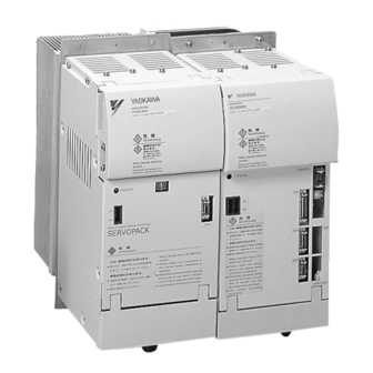
Introduction 1.2.2 Inverter 1.2.2 Inverter The appearance of the Inverter and the names of its components are shown below. Mounting Base 4-Mounting Holes Heatsink Upper Cover Front Cover Case Lower Cover Upper and Lower Covers Opened P/¨ Main Circuit Power Supply Input N/©... -
Page 30: Handling
Handling This chapter describes the checks required upon receiving an Inverter and Converter and describes installation methods. 2.1 Confirmation upon Delivery ... . . 2 -2 2.1.1 Inverter Nameplate Information . -
Page 31: Inverter Models
Are any screws or other components Use a screwdriver or other tools to check for tightness. loose? If any of the above checkpoints are not satisfactory, contact your Yaskawa representative. 2.1.1 Inverter Nameplate Information Nameplate Information Example of a Model for 200 VAC, 10HP (7.5 kW) MODEL : CIMR−M5A27P5... -
Page 32: Converter Models
SPEC : 20115E Converter Spec. Serial No. SER NO : N32764-000/V0004 MASS : 12 kg (26.5 lb) Mass MADE IN JAPAN YASKAWA ELECTRIC CORPORATION Fig 2.4 Converter Nameplate Model Designations CIMR - MR5 N 2 011 Converter VS-656MR5 Series Symbol Max. -
Page 33: Converter
Handling 2.1.3 Motor Nameplate Information Converter Specification Designation 2 011 5 E Symbol Voltage Revision symbol 3-phase 200 V class 3-phase 400 V class Symbol Symbol Max. applicable motor output Enclosure 5HP (3.7kW) Open chassis type 7.5HP (5.5kW) External heatsink cooling type 60HP (45kW) * For special specifications, a spec. -
Page 34: Inverter
55_C (131_F) and the intake air temperature to heatsink below 45_C (113_F). Overheating may cause a fire or damage to the unit. Install the VS-626M5 Inverter and VS-656MR5 Converter in the installation site described below. Maintain optimum conditions. 2.2.1 Installation Site Install the Inverter and Converter under the following conditions. -
Page 35: Operating Ambient Temperature
Handling 2.2.2 Operating Ambient Temperature Observe these additional cautions if taking the heatsink out of the panel from the opening in the control panel to cool outside. Install an oil-proof gasket on the fitting to prevent oil and dust from entering the unit. Without a gasket, oil and iron particles may enter the control panel, corrosion of the electronic parts and conductive parts may occur, and the resulting decrease of the insulation resistance may result in a ground fault. -
Page 36: Clearances
2.3 CLEARANCES 2.3 CLEARANCES Install the Inverter and Converter vertically and allow sufficient clearances for effective cooling as shown in Fig. 2.9 and Fig. 2.10. IMPORTANT 1. For the external dimensions and mounting dimensions, refer to 14.1.3 Dimensions. 2. Allowable intake air temperature to the Inverter and the Converter: S Open chassis type : 0_C to +45_C (32_F to 113_F) S External heatsink cooling type Inside of heatsink : 0_C to +45_C (32_F to 113_F) -
Page 37: Open Chassis Type
Handling 2.3.2 Open Chassis Type 2.3.2 Open Chassis Type 150 mm 5.91 inches) or more Max. 70 mm (2.76 inches) Converter Inverter 150 mm 5.91 inches) or more 5 mm (0.20 inches) or more (b) Side View (a) Front View Fig 2.10 Clearances for Open Chassis Type When using an Open-chassis Converter (11 kW or more) in combination with an Inverter (7.5 kW or less),... -
Page 38: Attaching The Digital Operator
D Do not use any screws other than the ones provided to mount the cable holder. Otherwise, the cable holder will not be attached securely. The VS-626M5 can support the Multi-functional Display Digital Operator (JVOP-132) as an option. The Exclusive-use Extension Cable (72616-W5301 or 72616-W5303) is required when connecting the Digital Operator with the Inverter. -
Page 39: Motor Installation Precautions
Handling 2.5.1 Installation Site 2.5 Motor Installation Precautions This section provides precautions for mechanical designing around the Motor to be installed. IMPORTANT The motor flange and shaft are coated with anti-corrosive paint or grease. Clean the flange, shaft, and key groove with paint thinner before installing the motor. -
Page 40: Coupling Motor And Machinery
2.5 Motor Installation Precautions 2.5.3 Coupling Motor and Machinery Consider the following conditions when coupling the Motor with the machinery. Direct Coupling Couple the Motor with the machinery so that the center of the motor shaft and that of the machinery shaft are on a straight line. -
Page 41: Wiring
Wiring This chapter provides typical connection examples of the Inverter and Con- verter to peripheral units, main circuit wiring specifications, and control cir- cuit wiring. 3.1 Connection with Peripheral Units ..3 -2 3.2 Connection Diagram . -
Page 42: Connection With Peripheral Units
Wiring 3.1 Connection with Peripheral Units WARNING D Always turn OFF the input power supply before wiring terminals. Otherwise, an electric shock or fire can occur. D Wiring should be performed only by qualified personnel. Failure to observe this warning can result in an electric shock or a fire. D Make sure to ground the ground terminal (200V class: Ground to 100Ω... - Page 43 3.1 Connection with Peripheral Units The following shows standard connections of the VS-626M5 with peripheral units. Power Supply: Power Supply: 200 VAC, 200 VAC, 3-phase (200 V Class) or Single-phase 400 VAC, 3-phase (400 V Class) Molded-case Circuit Molded-case Circuit...
- Page 44 The following figure shows the system configuration of the Inverter compatible with YENET1200 commu- nications. For details on the connections of an NC machine and servo units, refer to the manual for the NC ma- chine. VS-656MR5 Converter Unit 51CN VS-626M5 Inverter Unit 52CN 51CN Servo Unit 52CN...
-
Page 45: Connection Diagram
3.2 Connection Diagram 3.2 Connection Diagram The connection diagram of the Inverter and Converter is shown in Figures 3.3 and 3.4. Figure 3.3 is for a M5A Inverter model for stand-alone drives and Figure 3.4 is for a M5N model for NC systems. 3MCCB Motor Cooling Fan... - Page 46 Wiring 3MCCB Connection Bus Bar VS-656MR5 1MCCB 1MC P1N1 Power Cable Servo Unit VS-626M5 R/L1 3-Phase S/L2 200 VAC 51CN 51CN 52CN 52CN T/L3 2MCCB Single-phase A1/r 200 VAC A2/t Flat Cable Flat Cable Ground (100 Ω or less) Digital...
-
Page 47: Wiring Main Circuit Terminals
3.3 Wiring Main Circuit Terminals 3.3 Wiring Main Circuit Terminals This section provides information on the specifications, functions, configuration, and wiring of main circuit terminals. 3.3.1 Wires and Suitable Crimp Connectors Select wires or crimp connectors to be used from the following table. Table 3.1 200 V Class Converter Power Cable Specifications Wire Sizes... - Page 48 Wiring 3.3.1 Wires and Suitable Crimp Connectors Notes: 1. Wire size is selected assuming external suspended wiring of single 3-core cables at an ambient temperature of 30°C (86° 2. If ambient temperature exceeds 30°C (86° , the allowable current of wire may be lowered. 3.
- Page 49 3.3 Wiring Main Circuit Terminals 2. If ambient temperature exceeds 30°C (86° ), the allowable current of wire may be lowered. 3. Temperature for each wire indicates the maximum allowable conductor temperature. Table 3.3 200 V Class Inverter Power Cable Specifications Wire Sizes Tighten- UL-approved...
- Page 50 Wiring 3.3.1 Wires and Suitable Crimp Connectors Table 3.4 400 V Class Inverter Power Cable Specifications Wire Sizes Tighten- UL-approved 600 V Vinyl- 600 V Cross- 600 V Rubber-in- Model CIMR- Terminal 75°C (167°F) sheath Insulated linked Polyethy- sulated Cabtyre Terminal Symbols Screw Torque...
- Page 51 3.3 Wiring Main Circuit Terminals Table 3.5 Terminal Screws for 200 V Class Motors Inverter Standard Motor Winding Selection Motor Model Model Terminal Screws Cooling Fan Model Cooling Fan Terminal Screws CIMR-M5j UAASK- (U, V, W, ) Terminals UAASKj-jjFZ Terminals (U, V, W, ) (Z1, Z2, Z3) (Z1, Z2, Z3)
- Page 52 Wiring 3.3.1 Wires and Suitable Crimp Connectors Table 3.7 Closed-loop Crimp Connector Sizes (JIS C 2805) (For 200 V and 400 V Classes) Wire Sizes Terminal Screws Closed-loop Crimp Connectors Connectors M3.5 1.25 to 3.5 1.25 to 4 M3.5 1.25 to 3.5 0 75 0.75 1.25 to 4...
-
Page 53: Functions Of Main Circuit Terminals
3.3 Wiring Main Circuit Terminals 3.3.2 Functions of Main Circuit Terminals The following tables outline the functions of the main circuit terminals. Table 3.8 Converter Main Circuit Terminals Voltage Symbol Name Functions Class R/L1 3-phase Main circuit power supply S/L2 200 to 220 VAC 50 Hz input T/L3... - Page 54 Wiring 3.3.2 Functions of Main Circuit Terminals Table 3.9 Inverter Main Circuit Terminals Voltage Symbol Name Functions Class P/¨ 270 to 325 VDC Main circuit power supply input N/© (Supplied from converter) 282 to 325 VDC Control power supply input (Supplied from converter) Single-phase Heatsink...
-
Page 55: Main Circuit Configuration
3.3 Wiring Main Circuit Terminals 3.3.3 Main Circuit Configuration The following diagrams show the main circuit configurations. 200 V Class External Heatsink Cooling Type Converter (VS-656MR5) Inverter (VS-626M5) CIMR−MR5j23P75 to 27P55 CIMR−M5j23P75 to 27P55 U/T1 R/L1 S/L2 V/T2 T/L3 W/T3 −... - Page 56 Wiring 3.3.3 Main Circuit Configuration 200 V Class Open Chassis Type Converter (VS-656MR5) Inverter (VS-626M5) CIMR-MR5j23P70 to 27P50 CIMR-M5j23P70 to 27P50 U/T1 R/L1 S/L2 V/T2 T/L3 W/T3 − − Power A1/r Control Circuit Supply (RCC) A2/t Power Supply Control Circuit...
- Page 57 3.3 Wiring Main Circuit Terminals 400 V Class External Heatsink Cooling Type Converter (VS-656MR5) Inverter (VS-626M5) CIMR-M5j45P55 to 47P55 CIMR-MR5j45P55 to 47P55 U/T1 R/L1 V/T2 S/L2 W/T3 T/L3 − − Power A1/r Supply Control Circuit (RCC) A2/t Power Control Circuit...
- Page 58 Wiring 3.3.3 Main Circuit Configuration 400 V Class Open Chassis Type Converter (VS-656MR5) Inverter (VS-626M5) CIMR-MR5j45P50 to 47P50 CIMR-M5j45P50 to 47P50 U/T1 R/L1 S/L2 V/T2 T/L3 W/T3 − − Heatsink Cooling Fan Power A1/r Supply Control Circuit (RCC) A2/t Power...
-
Page 59: Main Circuit Connection Diagrams
A1/r 200 VAC A2/t (Note) Converter (VS-656MR5) Inverter (VS-626M5) CIMR-MR5j23P75 to 20375 CIMR-M5j23P75 to 20375 Note: No ground terminals are provided on the 23P7 through 27P5 models. Fig 3.9 Main Circuit Connections for 200 V Class External Heatsink Cooling Type... - Page 60 V/T2 W/T3 Single-phase A1/r A2/t 200 VAC Inverter (VS-626M5) Converter (VS-656MR5) CIMR-M5j45P55 to 40455 CIMR-MR5j45P55 to 40455 Note: No ground terminals are provided on the 45P5 through 47P5 models. Fig 3.11 Main Circuit Connections for 400 V Class External Heatsink Cooling Type...
-
Page 61: Wiring The Main Circuit
3.3 Wiring Main Circuit Terminals 3.3.5 Wiring the Main Circuit This section provides information on the main circuits of the Converter and Inverter and information on wiring the ground lines. Wiring Precautions for Main Circuit Input Installation of Molded-case Circuit Breaker (MCCB) Make sure to connect MCCB between the main circuit power supply input and VS-656MR5 input termi- nals R/L1, S/L2 and T/L3 to protect wiring. - Page 62 Wiring 3.3.5 Wiring the Main Circuit Example 1 Use an exclusive noise filter Correct Power MCCB Supply specified for inverters. Noise Filter 656MR5 626M5 MCCB Other Control Device Fig 3.13 Using Input Noise Filter Example 2 Incorrect Do not use general-purpose filters Power MCCB Supply...
- Page 63 3.3 Wiring Main Circuit Terminals Strict Prohibition of Installation of Magnetic Starter Do not connect a phase advancing capacitor or LC/RC noise filter to the output circuit, or otherwise the Inverter may be damaged or the internal parts of the Inverter may be damaged. Dealing with Emission Noise To reduce the emission noise from output side, wire the signal lines together in a grounded metallic con- duit.
-
Page 64: Wiring Control Circuit Signals
S 10136- 3000VE Sumitomo 3M Control signals 10236-52A2JL S ·10336- (36P) Ltd. Control PC 52A0-008 Board (case) (VS 626M5) (VS-626M5) S 10120- 3000VE Encoder signal Sumitomo 3M 10220-52A2JL S 10320- (20P) input Ltd. 52A0-008 (case) S 10114- 3000VE... - Page 65 Composite KQVV-SW Cable (AWG22 x 3 C + 20P: 12 mm (0.47 inches) dia. max. AWG26 x 6P) 9CN, 10CN (14P) Yaskawa’s drawing No.: BDP8409123 (with no 14p: 8 mm (0.31 inches) dia. max. connector) 4CN (8P) JKEV-SB (JCS) Shielded Twisted-pair Cable 11 mm (0.43 inches) dia.
-
Page 66: Terminal Arrangement Of Control Signal Connector
Wiring 3.4.2 Terminal Arrangement of Control Signal Connector 3.4.2 Terminal Arrangement of Control Signal Connector Figures 3.18 and 3.19 show the terminal arrangements of the control signal connectors. 3 -26... - Page 67 3.4 Wiring Control Circuit Signals 51CN 5CN, 52CN +24VIN — — +24VIN /EXT1 ESP0 ESP0 /EXT1 /EXT2 ALM± ALM± /EXT2 ESP1 ALMC ALMC ESP1 CONFLT CONRDY CONRDY CONFLT CONRST AXRUN AXRUN CONRST +24V +24V +24V +24V +24V +24V +24V +24V +24V +24V +24V...
-
Page 68: Control Signal Functions
Wiring 3.4.3 Control Signal Functions 8CN (Option) — *SPB *CPC *SPA − − 51CN/52CN *SPC *CPB CHARGE CHARGE 4CN Encoder Method Orientation *CPA Card Card 9CN (Option) — *SPBO — SPBO — *SPAO — SPAO 9CN 10CN — *SPCO — SPCO —... -
Page 69: Control Signal Functions
3.4 Wiring Control Circuit Signals Control Signal Functions Table 3.12 Control Circuit Signals (1CN to 4CN) Connector Signal Function Signal Level +24VIN − − /EXT1 − − /EXT2 − − ESP0 − − ESP1 − − ALM+ − − ALM− −... - Page 70 Wiring 3.4.3 Control Signal Functions Table 3.13 Control Circuit Signals (6CN) Connector Signal Function Signal Level Related Constants +15V +15V output +15V Load current: 10mA or less Shield (0V) − C1-26 10 C1-38 bit 5 C1-26, 10, C1-38 bit 5 0 to ±10V SCOM Analog speed reference input...
- Page 71 3.4 Wiring Control Circuit Signals Table 3.14 Control Circuit Signals (8CN, 9CN, 10CN) Connector Signal Function Signal Level 4, 5, 6 +5V power supply for encoder Load current: 350mA or less 1, 2, 3 Encoder power supply 0 V − *CPA RS 422A specification RS-422A specification...
-
Page 72: Sequence Input Signal Circuit (For Stand-Alone Drive)
Wiring 3.4.4 Sequence Input Signal Circuit (for Stand-alone Drive) 3.4.4 Sequence Input Signal Circuit (for Stand-alone Drive) Design the input signals in consideration of the following conditions. The 12-bit digital reference signals into the Inverter’s 1CN connectors and the sequence input signals into 6CN connectors can be 0 V, 24 V, or external common signals. -
Page 73: Sequence Output Signal Circuit (For Stand-Alone Drive)
3.4 Wiring Control Circuit Signals 3.4.5 Sequence Output Signal Circuit (for Stand-alone Drive) Design the output signals in consideration of the following conditions. The output method allows either a +24 V or 0 V common. Signal outputs are insulated with photocouplers. Prepare a +24 V power supply for the output signal. The output current capacity is 50 mA at 24 V. - Page 74 Wiring 3.4.6 Precautions for Control Signal Wiring Use twisted shielded wires for motor encoder signal lines and connect both ends as shown below. Armor Shielded Sheath To encoder shielded To inverter shielded sheath terminal sheath terminal Insulate these parts with insulating tape. Fig 3.23 Shielded Wire Termination (Shielded at Both Ends) 3 -34...
-
Page 75: Wiring Inspection
3.5 Wiring Inspection 3.5 Wiring Inspection After completing installation and wiring, check for the following items. Never do a control circuit buzzer check. Confirm that the capacities and models of the Motor, Inverter, and Converter and the specifications of the machine are compatible. Check the nameplates on the Motor, Inverter, and Converter. Confirm that all devices are wired according to the connection diagram with no mistakes. -
Page 76: Control Signals
Control Signals This chapter provides detailed information on each control signal. 4.1 Sequence Input Signals ....4 -2 4.1.1 Connecting Sequence Input Signals ... . 4 -2 4.1.2 Selecting Sequence Input Signals . -
Page 77: Sequence Input Signals
Control Signals 4.1.1 Connecting Sequence Input Signals 4.1 Sequence Input Signals This section provides information on the connections, functions, displays, and meaning of the sequence input signals. 4.1.1 Connecting Sequence Input Signals The connections of sequence input signals vary between stand-alone drives and NC systems as described below. -
Page 78: Status Display Of Sequence Input Signals
4.1 Sequence Input Signals 4.1.3 Status Display of Sequence Input Signals The ON/OFF status of input signals can be checked with the U10-09 and U1-19 operating status displays. As explained below, the LED indicators of the Digital Operator show the status of each signal. Refer to Chapter 5. - Page 79 Control Signals 4.1.4 Details on Sequence Input Signals Speed Reference − Operation signals [FWD] CCW (Forward) CW (Reverse) [REV] CW (Reverse) CCW (Forward) When the FWD or REV signal is turned OFF while the motor is in operation, the motor will stop due to regenerative braking.
- Page 80 4.1 Sequence Input Signals TLH/TLL (Torque Control Signal H/L) The TLH signal functions when 6CN-10 turns ON. The TLL signal functions when 6CN-11 turns ON. The TLH and TLL signals are used to temporarily control the torque of the motor in operation. When the TLH or TLL signal is turned ON, the torque will be controlled and the TLE torque control signal will be output.
- Page 81 Control Signals 4.1.4 Details on Sequence Input Signals SV (Servo Mode Signal) SV Function Selection: 6CN-12 will be the SV signal if bit 03 of the C1-36 selection signals (SEL1) is turned ON. C1−36 The servo mode for a solid tap or similar device will be switched to when 6CN-12 turns ON. In the servo mode, the speed loop gain and other control constants for servo mode will be used.
- Page 82 4.1 Sequence Input Signals The RST signal is enabled only after the protective circuit operates. The system cannot be reset while the FWD , REV, or ORT signal is ON. The RESET switch of the Digital Operator has the same function as the RST signal. The system is reset on the rising edge of the RST signal.
- Page 83 Control Signals 4.1.4 Details on Sequence Input Signals MGR/LGR (M Gear/L Gear Selection Signal) The MGR signal will be selected when 6CN-18 is turned ON. The LGR signal will be selected when 6CN-17 is turned ON. The MGR and LGR signals are used to change parameters, such as the gear ratio and gain, to ensure the optimum control of the load according to the gear selection of the load shaft.
-
Page 84: Analog Speed Reference
4.2 Analog Speed Reference 4.2 Analog Speed Reference This section proves detailed information on the analog speed reference signal for stand-alone drives M5A. SCOM (Analog Speed Reference Input) Connector number: 6CN Pin number: 3 The rated input voltage is ±10 VDC. Set the motor speed at the rated input voltage (i.e., a 100% speed reference) in C1-26 (S100), the rated speed setting constant. -
Page 85: Using A 12-Bit Digital Speed Reference
Control Signals 4.3 Using a 12-bit Digital Speed Reference This section provides information on using a 12-bit digital speed reference input (for stand-alone drive systems M5A only). D1 through D12 (12-bit Digital References 1 through 12) Connector number: 1CN Pin numbers: 19 through 30 12-bit Digital Reference Signal Function Selection: 1CN-19 to 1CN-30 will be the 12-bit Digital Refer- ence if bit 07 of the C1-36 selection signals (SEL1) is turned OFF. - Page 86 4.3 Using a 12-bit Digital Speed Reference Digital Speed Settings Signal 1CN Pin Number 12-bit Binary 3-digit BCD 2-digit BCD 1024 2048 All signals will be ON with the rated speed reference set in C1-26 if the 12-bit binary setting is selected. If the 3- or 2-digit BCD setting is selected, a rated speed reference of 999 or 99 will be set in C1-26 respectively.
-
Page 87: Sequence Output Signals
Control Signals 4.4.1 Connecting Sequence Output Signals 4.4 Sequence Output Signals This section provides information on the connections, functions, displays, and meanings of the sequence output signals. 4.4.1 Connecting Sequence Output Signals The connection of sequence output signals varies between stand-alone drives and NC systems as described below. -
Page 88: Details On Sequence Output Signals
4.4 Sequence Output Signals 4.4.4 Details on Sequence Output Signals This section provides information on each of sequence output signal. Pin numbers are given for indepen- dent drive operation (M5A). Refer to the manual for the NC machine for sequence output signals and out- put addresses. - Page 89 Control Signals 4.4.4 Details on Sequence Output Signals SDET (Speed Detection Signal) Connector number: 6CN Pin numbers: The SDET signal will turn ON when the motor speed reaches the preset value or less. The speed detection level is set between 0% and 100% in the C1-21 (SD ) control constant.
- Page 90 4.4 Sequence Output Signals CHWE (Winding Selection Completion Signal) Connector number: 6CN Pin numbers: CHWE signals completion of motor winding selection. The CHWE signal is usually ON when the motor is in operation. When the CHW signal is ON, the CHWE signal will turn OFF until the winding is switched.
- Page 91 Control Signals 4.4.4 Details on Sequence Output Signals FLT (Fault Bit Signal) Connector number: 6CN Pin numbers: The motor current will be shut off instantly when the protective circuit operates for overcurrent or over- load protection and the motor will coast to a stop. The FLT signal will be output when the current is shut off.
- Page 92 4.4 Sequence Output Signals TALM (Minor Fault Signal) Connector number: 6CN Pin numbers: The TALM signal turns ON when a motor overheat alarm 1, heatsink overheat alarm 1, or control card temperature alarm 1 is detected. The system will continue operating. The FLTL signal will turn ON if any of the following conditions continues while the TALM signal is ON, the current will be shut off, and the system will stop.
-
Page 93: Analog Monitor Signals
Control Signals 4.5 Analog Monitor Signals The following conditions and specifications apply to analog output signals (for stand-alone drive systems M5A only). SM (Speed Meter Signal) Connector number: 6CN Pin number: 47 The motor speed can be monitored with an external speed meter connected. The SM signal is a DC voltage signal that is output in proportion to the speed regardless of the direction of rotation. -
Page 94: Encoder Pulse Input Circuit
4.6 Encoder Pulse Input Circuit 4.6 Encoder Pulse Input Circuit Phase A, B, and C (origin) signals [PA, *PA, PB, *PB, PC, *PC] are input into the 2CN connector from the 1024 P/R motor encoder. An asterisk indicates a reversed signal. The input signals have the following specifications. Signal Configuration 90°... -
Page 95: Encoder Pulse Output Circuit
Control Signals 4.7 Encoder Pulse Output Circuit Phase A, B, and C (origin) signals are output from the motor encoder. An asterisk indicates a reversed signal. The output signals have the following specifications and can be used for position feedback. Signal Configuration 90°... -
Page 96: Operating The Digital Operator
Operating the Digital Operator This chapter explains the functions, operating methods, details on control constants for the Digital Operator. 5.1 Function of the Digital Operator ..5 -2 5.2 Display Mode Configuration . -
Page 97: Function Of The Digital Operator
Operating the Digital Operator 5.1 Function of the Digital Operator The Digital Operator enables the following: Display of Control Signal Status Status of control signals of each unit is displayed by monitoring the status of operation. For the display items, see Chapter 11 Operating Status Displays. Display and Setup of Control Constants Control constants must be set up for normal operation in compliance with the specifications. - Page 98 5.1 Function of the Digital Operator Fig. 5.1 shows the display section and operation keys of the Digital Operator, and Fig. 5.2 shows the LED dis- play status of the RUN and STOP keys. Table 5.1 shows the displayed characters and the corresponding alpha- bets and numbers, and Fig.
- Page 99 Operating the Digital Operator Table 5.1 Indication of Numbers and Letters by 7-segment LED Numbers Letters − − − − − − − − − − − − − − − − − Note: “—” is not displayed. 1: ON 0: OFF Selection signal 0 (OFF) indicates “...
-
Page 100: Display Mode Configuration
5.2 Display Mode Configuration 5.2 Display Mode Configuration The following figure shows the displays of the Digital Operator. Whenever the DSPL (display selection) key is pressed, the display mode will change. Control power ON All LEDs light (for 1.5 s). PROM version No. -
Page 101: Key Operations And Display
Operating the Digital Operator 5.3.1 Indication at Power-ON 5.3 Key Operations and Display This paragraph describes how to operate the Digital Operator keys and display. 5.3.1 Indication at Power-ON Digital Operator display at control power supply ON is shown below. Description Digital Operator Display Remarks... -
Page 102: Operation Status Display Mode
5.3 Key Operations and Display 5.3.3 Operation Status Display Mode To check data in operation status display mode, do as follows. The following shows the example where U1-09 (sequence input signal status) is to be changed. Description Digital Operator Display Remarks Sequence S U1-01 is displayed. -
Page 103: Digital Operator Operation Mode
Operating the Digital Operator 5.3.5 Digital Operator Operation Mode IMPORTANT The following are constants that cannot be changed during operation: C1-25 to 59, C2-09 to 27, C3-09 to 25: Cannot be changed during operation. Change when stopped. C1-01 to 24, C2-01 to 08, C3-01 to 08: Can be changed during operation or when stopped. 5.3.5 Digital Operator Operation Mode In Digital Operator operation mode, operation is enabled by commands from the Digital Operator. - Page 104 5.3 Key Operations and Display Set the speed reference in Digital Operator operation to d1-02. Description Digital Operator Display Remarks Sequence S Select d1-01. DSPL S Select d1-02. S Display d1-02 data con- DATA tents. ENTER S Set speed reference (25%). Speed reference is displayed as a per- ...
-
Page 105: Fault Display Mode
Operating the Digital Operator 5.3.6 Fault Display Mode 5.3.6 Fault Display Mode If a protective function is activated because of a fault, the fault code is displayed. Up to six faults are re- corded to view the order of a series of faults. Display Example Time Fault Reset... -
Page 106: Fault Record Display Mode
5.3 Key Operations and Display 5.3.7 Fault Record Display Mode Up to six faults can be displayed in order from most recent to oldest. Fault No. Fault Occurrence No. (1 to 6) The larger the number, the older the fault data. Display Example Time 42 occurred... -
Page 107: Trial Operation
Trial Operation This chapter explains the setup for trial operation, and gives examples of Digital Operator operations and trial operation. 6.1 Procedure ......6 -4 6.2 Trial Operation Procedure . -
Page 108: Speed Control Mode Adjustment Procedure
Trial Operation 6.4.13 Positioning Completion Detection Width (ZFIN: C2-09 and C3-09) and Positioning Completion Cancel Width (ZCAN: C2-10 and C3-10) ....6 -13 6.4.14 Orientation Speed (SORT : C2-11 and C3-11) 6 -14 6.4.15 BCD Stop Position Reference Resolution... - Page 109 WARNING D Turn ON the power supply only after closing the upper and lower covers. Do not open the covers while current is flowing. Failure to observe this warning can result in an electric shock. D The Digital Operator stop button can be disabled by a function setting; you must install a sepa- rate emergency stop switch.
-
Page 110: Procedure
Trial Operation 6.1 Procedure Perform trial operation according to the following flowchart. Item Details Refer- ence Page Installation and Mounting Install the Inverter and Converter according to the installation conditions. 1 -5 S Check that the installation conditions are satisfied. Wiring Connect the power supply and peripheral devices. -
Page 111: Trial Operation Procedure
6.2 Trial Operation Procedure 6.2 Trial Operation Procedure This section explains in detail the procedure shown in the flowchart on the preceding page for the trial operation. 6.2.1 Checking the Power Supply Voltage Turn OFF the MCCB on the Converter power supply, and check the power supply input voltage supplied to the Converter on the primary side of the MCCB. -
Page 112: Checking The Motor Cooling Fan
Trial Operation 6.2.5 Checking the Motor Cooling Fan 6.2.5 Checking the Motor Cooling Fan When the main circuit power supply is turned ON, the Motor cooling fan will start to rotate. Check that the direction of the Motor cooling flow is as shown in the Fig.6.1 . With the standard specifications configu- ration, the cooling flow enters from the load side, and is vented on the side away from the load. -
Page 113: Converter And Inverter Led Displays
6.3 Converter and Inverter LED Displays 6.3 Converter and Inverter LED Displays This section explains the Converter and Inverter LED displays. 6.3.1 Display Details Tables Details on the 7-segment LED displays on the Inverter and Converter are shown in the following tables. Table 6.2 Seven-segment LED Display Details Converter... -
Page 114: Display When An Error Occurs
Trial Operation 6.3.3 Display when an Error Occurs 6.3.3 Display when an Error Occurs If multiple errors are detected in the Inverter and Converter, the details for a maximum of four Converter errors and six Inverter errors will be saved. Consequently, the order in which the errors occurred can be viewed. -
Page 115: Constant Settings
6.4 Constant Settings 6.4 Constant Settings This section explains the user constant functions and settings. 6.4.1 User Constant Functions Table A table of user constant functions is shown below. Change the constant set values depending on the operat- ing specifications. Refer to 5.3.4 Control Constant Display Mode for setting methods. Check that the following constant set values match the operating specifications. - Page 116 Trial Operation 6.4.2 Soft Start Time Setting (T : C1-10) 6.4.2 Soft Start Time Setting (T : C1-10) −1 The Inverter speed base is the time set to be taken from 0 min . to the rated speed (C1-26), or from the rated speed setting to 0 rotations/min.
-
Page 117: Motor Code Selection (Mtr: C)
(Motor Code Selection Error) will be displayed. Also, if no Motor code has been registered, error code AL-E1 (Motor Code Not Registered) will be displayed. If the motor being used is not listed in the following table, please contact your Yaskawa representative for motor code information. - Page 118 Trial Operation 6.4.9 Motor Code Selection (MTR: C1-25) IMPORTANT Precautions when Changing the Motor Code After changing the Motor code, be sure to turn OFF the control power supply. Next, check that the Digital Operator display is no longer lit, and then turn ON the power supply again. This operation will enable the new Motor code.
-
Page 119: Magnetic Sensor Orientation
6.4 Constant Settings 6.4.10 Rated Speed (S : C1-26) Set the rated speed to match the machine specifications. The Motor will operate at this rated speed when −1 the speed reference value input is 100%. The rated speed can be set between 100 min and the maximum Motor speed. - Page 120 Trial Operation 6.4.14 Orientation Speed (S : C2-11 and C3-11) 6.4.14 Orientation Speed (S : C2-11 and C3-11) Make sure the Motor has stopped before setting the orientation speed. The orientation speed settings are determined by the moment of inertia (including the Motor shaft), and the torque.
- Page 121 6.4 Constant Settings 6.4.15 BCD Stop Position Reference Resolution (P : C2-12 and C3-12) Make sure the Motor has stopped before setting the BCD stop position reference resolution. The BCD stop position reference resolution can be set between 0.5_ and 180.0_, but the stop position refer- ence must be within ±360_.
-
Page 122: Speed Control Mode Adjustment Procedure
Trial Operation 6.5 Speed Control Mode Adjustment Procedure First check that the Motor is operating normally, and then adjust the speed control mode according to the adjust- ment procedure shown below. Also, if replacing the Motor or Inverter, be sure to perform the adjustments shown below. - Page 123 6.5 Speed Control Mode Adjustment Procedure Adjustment Item and Procedure Details Speedometer signal adjustment value (C1-16) (P.U.) Is speedometer display correct? (See note.) Is meter display greater than motor speed? 1.5 (C1−16) 0.9 1.0 Adjust C1-16 (SM ) to C1-16 = Actual measured motor speed/Speedometer smaller than current value.
-
Page 124: Features
Wide Constant Power Control Using Winding Selection This chapter explains the features, connections, operations, switching meth- ods, and precautions for wide constant power control using winding selec- tion. 7.1 Features of the Winding Selection Wide Constant Power Drive ....7 -2 7.2 Winding Selection Motor Standard Connections... -
Page 125: Features Of The Winding Selection Wide Constant Power Drive
Wide Constant Power Control Using Winding Selection 7.1 Features of the Winding Selection Wide Constant Power Drive The AC main shaft Motor winding selection function is provided as an effective method of increasing the constant power control range of the machine-tool main shaft drive. The features of the function are shown be- low. -
Page 126: Winding Selection Motor Standard Connections
7.2 Winding Selection Motor Standard Connections 7.2 Winding Selection Motor Standard Connections As shown in the following diagram, this system requires winding selection signals in addition to speed refer- ence signals such as FWD and REV. In winding selection, a special magnetic contactor is used that can operate directly from the Inverter. -
Page 127: Motor Characteristics
Wide Constant Power Control Using Winding Selection 7.3 Motor Characteristics Motors with switchable windings with a 1:12 constant power range have a 1:4 constant power range for both the low-speed and high-speed windings, as shown in the following diagram. This can be written as S = 4. -
Page 128: Winding Selection Operation
7.4 Winding Selection Operation 7.4 Winding Selection Operation The timing chart for switching from low-speed to high-speed windings is shown in the following diagram. Approx. 170 ms Winding selection signal (CHW) Gate block Gate block Magnetic contactor for winding selection Winding 10-11 Auxiliary... -
Page 129: Winding Selection Methods
Wide Constant Power Control Using Winding Selection 7.5.1 M Code Winding Selection Method 7.5 Winding Selection Methods When performing winding selection, design the reference circuits referring to the following three methods, to make sufficient use of the motor characteristics. 7.5.1 M Code Winding Selection Method For the main shaft drive of the machine-tool, view the winding selection as an electric gear, and use the numeric control M codes (M41: Low-speed winding, M42: High-speed winding) as shown in the flow- chart and timing chart below. - Page 130 7.5 Winding Selection Methods M41 S500 M42 S2000 M41 S500 [AGR] [CHW] [CHWE] −1 2000 min −1 Speed 500 min −1 500 min reference Speed Fig 7.5 Timing Chart 7 -7...
-
Page 131: Automatic Winding Selection Methods
Wide Constant Power Control Using Winding Selection 7.5.2 Automatic Winding Selection methods 7.5.2 Automatic Winding Selection methods This section explains the automatic winding selection methods. There are two methods. Using the Inverter Speed Detection Signal The flowchart and timing chart for performing automatic winding selection judging from the actual motor speed alone using the Inverter speed detection signal (SDET) are shown below. - Page 132 7.5 Winding Selection Methods S500 S2000 S500 [SDET] [CHW] [CHWE] −1 2000 min −1 500 min −1 500 min Speed reference Speed Fig 7.7 Timing Chart Using Speed Reference and the Inverter Speed Detection Signal This method performs winding selection by judging whether the speed reference and actual motor speed are within the high-speed winding selection range or the low-speed winding selection range, using the speed reference and the Inverter speed detection signal (SDET).
- Page 133 Wide Constant Power Control Using Winding Selection 7.5.2 Automatic Winding Selection methods Set the host controller speed reference judgment level S and the hysterisis level ∆S to the same values as the Inverter speed detection signal level C1-21 (SD ) and the speed detection signal detection width C1-22 (SD Table 7.1 Winding Selection Conditions...
-
Page 134: Winding Selection Control Precautions
7.6 Winding Selection Control Precautions 7.6 Winding Selection Control Precautions Refer to the following precautions when designing winding selection control. If the signal wire breaks or the magnetic contactor for winding selection malfunctions, the Motor will stop, and the operation program will not proceed. At this time, perform an overtime check after the set time, notify the operators immediately, and stop the winding selection operation by judging it to be defective (AL-20). -
Page 135: Orientation Control Using An Encoder
Orientation Control Using an Encoder This chapter explains methods of control using the Encoder Orientation Card. 8.1 Device Configuration ....8 -2 8.2 Standard Connection Diagram . -
Page 136: Device Configuration
Orientation Control Using an Encoder 8.1 Device Configuration Orientation control with an Encoder is used for positioning based on dividing 1 rotation into 4,096 steps (i.e., a resolution of 0.088_), 12-bit binary, or 3-digit BCD stop angle references using the load shaft (machine-tool main shaft, etc.) Encoder, and the Encoder Orientation Card. -
Page 137: Standard Connection Diagram
8.2 Standard Connection Diagram 8.2 Standard Connection Diagram Figure 8.2 shows the standard connections to use a motor encoder signal with the load shaft and motor shaft linked in a 1:1 configuration. Figure 8.3 shows the standard connections to use the load shaft encoder signal. In both cases, the example shows an stand-alone drive (CIMR-M5Ajjjj). -
Page 138: Orientation Control Using An Encoder
Orientation Control Using an Encoder 3MCCB Special bus bar Motor Cooling fan 3-phase 1MCCB P1N1 power VS−656MR5 200 VAC supply cable VS−626M5 R/L1 3-phase S/L2 200 VAC T/L3 51CN U/T1 V/T2 W/T3 2MCCB 2MC Load shaft A1/r Gearbox 1-phase Flat cable 300 VAC A2/t 52CN... -
Page 139: Orientation Specifications
8.3 Orientation Specifications 8.3 Orientation Specifications This section explains the specifications for devices required for encoder orientation. 8.3.1 Standard Specifications The following table shows the standard specifications for encoder orientation. Table 8.1 Standard Specifications Item Load Shaft Encoder Motor Encoder Positioning Method Absolute or incremental Positioning Detection Method... -
Page 140: Dimensions
* 1. Mount to prevent backlash, as this may cause inaccurate positioning. * 2. A Shaft Load Encoder without a flange is also available. * 3. Ask your Yaskawa representative for Load Shaft Encoders for built-in motors. Fig 8.6 Dimensions of Load Shaft Mounted Encoder... -
Page 141: Load Shaft Encoder Connector Terminal Arrangement
8.5 Load Shaft Encoder Connector Terminal Arrangement 8.5 Load Shaft Encoder Connector Terminal Arrangement The connector terminal arrangement for the Load Shaft Encoder is shown in the following diagram. Encoder: MS3102A20-29P Cables: MS3106A20-29S (Straight plug, solid shell) MS3106B20-29S (Straight plug, 2-piece shell) MS-3108B20-29S (L−plug, 2-piece) MS3057-12A (Cable Clamp) Notes: 1. -
Page 142: Important Points For Encoder Mounting And Wiring
Make sure the signal cable between the Orientation Card and the Load Shaft Encoder is 20 m maxi- mum. Yaskawa has prepared signal cables to the specifications shown in the following table. Purchase signal cables in the standard length required for your applications. -
Page 143: Stop Position Reference Signals
8.7 Stop Position Reference Signals 8.7 Stop Position Reference Signals This section explains the stop position reference signal connections, status displays, and signal details. 8.7.1 Stop Position Reference Signal Connections Connections for the stop position reference signal differ for stand-alone drive use and NC system use, as shown below. - Page 144 Orientation Control Using an Encoder 8.7.3 Details of the Stop Position Reference Signal Signal Pin Number Binary Without Sign With Sign With Sign 1024 1024 2048 Sign Sign When using signed binary data, the meaning of the signal will depend on the sign (+ or −). If the sign is positive, the total number of bit pulses input is added: 0 0 1 0 1 0 0 1 0 0 1 256+ 64...
-
Page 145: Functions
8.8 Functions 8.8 Functions This section explains in detail the Encoder orientation control code functions. IMPORTANT Orientation Control Application Precautions In the following cases, be sure to adjust the tuneup and parameters before using the orientation function. S When using the orientation function for the first time after mounting the M5 to the machine S When replacing the Motor or Encoder S When changing the wiring between devices For details on the tuneup, refer to the adjustment procedure. -
Page 146: Incremental Positioning
Orientation Control Using an Encoder 8.8.2 Incremental Positioning 8.8.2 Incremental Positioning Incremental positioning is used when positioning to a new stop position that adds to the current stop posi- tion a specified amount of travel (i.e., angle). If an incremental signal is input and an orientation signal is input again after absolute positioning has been completed, the shaft stops at the new stop position according to the servo loop, and a completion signal is output at the same time. -
Page 147: Precautions On Orientation Control
8.8 Functions 8.8.3 Precautions on Orientation Control Design the sequence considering the following points when using the orientation function. The system will not restart unless the ORT signal is turned OFF if an emergency stop is performed during orientation. Keep the ORT signal OFF when the system is turned ON, or otherwise the system will not operate. Turn ON the ORT signal at least 15 ms after the EMG or RDY signal is turned ON. -
Page 148: Encoder Orientation Control Mode Adjustment Procedure
Orientation Control Using an Encoder 8.9 Encoder Orientation Control Mode Adjustment Procedure Adjust the encoder orientation according to the following flowchart. Be sure to perform the following adjust- ments if the Motor, Inverter, or Encoder are replaced. Adjustment Item and Procedure Details Initial Settings: Change Constants Using Digital Operator Turn ON the power supply. - Page 149 8.9 Encoder Orientation Control Mode Adjustment Procedure Adjustment Item and Procedure Details If a malfunction occurs during tuneup, reset the system, and then per- form the tuneup operation again. Turn OFF orientation signal (ORT). Tuneup completed Turn ON tuneup operation selection (Bit 4 of C2-22 turned ON). Tuneup completed.
-
Page 150: Magnetic Sensor Orientation Control
Magnetic Sensor Orientation Control This chapter explains control methods using a Magnetic Sensor Orientation Card. 9.1 Device Configuration ....9 -2 9.2 Standard Connections . -
Page 151: Device Configuration
Magnetic Sensor Orientation Control Device Configuration This configuration performs positioning to a fixed angle by detecting the position using a Magnetic Sensor mounted on a fixed part and a Magnet mounted to the rotating part of the load shaft. For this method of control, the following devices are required in addition to signals and speed references for forward and reverse rotation: Orientation signals and a Magnet for positioning references, a Magnetic Sensor, and a Magnetic Sensor Orientation Card. -
Page 152: Standard Connections
9.2 Standard Connections Standard Connections An example for an stand-alone drive (CIMR-M5Ajjjj) is shown in the following diagram. 3MCCB Special bus bar Motor Cooling fan 3-phase P1N1 power 200 VAC VS−656MR5 supply cable 1MCCB VS−626M5 R/L1 51CN 3-phase S/L2 U/T1 T/L3 V/T2 W/T3... -
Page 153: Standard Specifications
Magnetic Sensor Orientation Control 9.3.1 Standard Specifications Orientation Specifications This section explains the specifications for devices required for Magnetic Sensor orientation. 9.3.1 Standard Specifications The following table shows the standard specifications for Magnetic Sensor orientation. Table 9.1 Standard Specifications Item Details Position Detection Method Position change detection by magnetic flux using a Magnet and a Magnetic Sensor. -
Page 154: Magnetic Sensor Specifications
9.3 Orientation Specifications 9.3.3 Magnetic Sensor Specifications The specifications for the Magnetic Sensor are shown in the following table. Table 9.3 Magnetic Sensor Specifications Item Details FS-1378C FS-200A Power Supply Voltage 15 VDC ±5% 12 VDC ±10% Consumption Current 100 mA max. 50 mA max. -
Page 155: Dimensions
Magnetic Sensor Orientation Control 9.4.1 Magnetic Sensor Orientation Card (ETC62614X) Dimensions The dimensions for the Orientation Card, Magnet, and Magnetic Sensor are shown in the following diagrams. 9.4.1 Magnetic Sensor Orientation Card (ETC62614X) 10CN (Unit: mm) Note: The Magnetic Sensor Orientation Card can be shipped after being mounted to the Unit at the factory. -
Page 156: Magnetic Sensor
9.4 Dimensions 9.4.3 Magnetic Sensor FS-1378C FSH-1378C Magnetic Magnet direction of Sensor Head FSD-1378C TRC116-21A 10-7M Recep- travel 2−φ5.4 Detector tacle 6-core LCKV cable 1-groove 4.5 2.7 (Tajimimusen) 500 mm φ12 SPC 0.5 t 37.5 37.5 TRC116-12A 10-7F Plug Mounting cutaway (Tajimimusen) Detail at A 2−M4... -
Page 157: Connections Between Devices
Magnetic Sensor Orientation Control 9.5.1 Magnetic Sensor Signal Connections between Devices This section explains the connections between the devices used for Magnetic Sensor orientation control. 9.5.1 Magnetic Sensor Signal Using the FS-1378C Orientation card 10CN FSD-1378C (See note 1.) Magnetic FSH-1378C Position signal Sensor... -
Page 158: Control Signal Connector Terminal Arrangement
9.6 Control Signal Connector Terminal Arrangement Control Signal Connector Terminal Arrangement The terminal arrangement of the control signal connectors is shown below. 10CN Orientation Card SIG− SIG+ +15 V +12 V PCB connector: 10214-52A2JL Cable connector: 10114-3000VE 10314-52A0-008 (case) Notes:1. The terminal arrangement is viewed from the PCB connector. 2. -
Page 159: Magnet And Magnetic Sensor Mountings
Magnetic Sensor Orientation Control Magnet and Magnetic Sensor Mountings The Magnet is mounted directly to the load shaft as shown in the following diagram. The Magnetic Sensor is mounted to a part of the load shaft that does not rotate, but must be mounted so that the positioning of the center of the Magnet agrees exactly with the center of the Magnetic Sensor. -
Page 160: Mounting Precautions
9.8 Mounting Precautions Mounting Precautions Pay attention to the following precautions when mounting the Magnet and Magnetic Sensor. Mount the Magnet to the Load Shaft The position control loop is configured using the detection magnetic field of the Magnet. Mount the Mag- net on the load shaft (e.g., the main shaft of the machine-tool). - Page 161 Magnetic Sensor Orientation Control Load shaft Magnetic Sensor head pin groove Magnet detection standard hole (a) MG-1378BS/FS-1378C Load shaft FS-200 printed on the back (b) MG-1444S/FS-200 Fig 9.15 Magnet and Magnetic Sensor Mounting Directions 9 -12...
-
Page 162: Stop Position Reference Signal Details
9.9 Stop Position Reference Signal Details Stop Position Reference Signal Details The stop position reference input signal circuit, which controls the direction of the Magnetic Sensor orientation, is the same as for the sequence input signal. D1 to D12 (Stop Position Reference Signal) 12-bit Digital Reference Signal Function Selection: 1CN-19 to 1CN-30 will be the 12-bit Digital Refer- ence if bit 07 of the C1-36 selection signals (SEL1) is turned OFF. -
Page 163: Fixed Position Stopping Operation Using The Magnetic Sensor
Magnetic Sensor Orientation Control 9.10.1 Fixed Position Stopping Operation Using the Magnetic Sensor 9.10 Functions This section explains in detail the Magnetic Sensor orientation control mode functions. IMPORTANT Orientation Control Application Precautions In the following cases, be sure to adjust the tuneup and parameters before using the orientation function. S When using the orientation function for the first time after mounting the inverter to the machine S When replacing the Motor or Encoder S When changing the wiring between devices... -
Page 164: User-Set Position Stop Control Using Incremental Operations
9.10 Functions 9.10.2 User-set Position Stop Control Using Incremental Operations Incremental positioning is used when positioning to a new stop position that adds to the current stop posi- tion a specified amount of travel rotation (i.e., angle). If an incremental signal is input and an orientation signal is input again after fixed positioning has been completed, the shaft stops at the new stop position according to the servo loop and a completion signal is output at the same time. -
Page 165: Magnetic Sensor Orientation Control Mode Adjustment Procedure
Magnetic Sensor Orientation Control 9.11 Magnetic Sensor Orientation Control Mode Adjustment Procedure Adjust the Magnetic Sensor orientation according to the following flowchart. Be sure to perform the following adjustments if the Motor, Inverter, or Encoder is replaced. Adjustment Item and Procedure Details Initial Settings: Change Constants Using Digital Operator Turn ON the power supply. - Page 166 9.11 Magnetic Sensor Orientation Control Mode Adjustment Procedure Adjustment Item and Procedure Details If a malfunction occurs during tuneup, reset the system, and them per- form the tuneup operation again. Tuneup completed. (Bit 4 of C3-22 turned ON.) Turn OFF orientation signal (ORT). S Turn ON tuneup operation selection (C3-22 bit 4).
- Page 167 Magnetic Sensor Orientation Control Adjustment Item and Procedure Details Note: If there is no L gear selection in the machine specifications, omit the following L gear adjustment procedure. Check L Gear Selection Select L gear. Interface input status (U1-09) Turn ON orientation signal (ORT). Lit when L gear is selected.
-
Page 168: Control Constants
Control Constants The control constants of the VS-626M5 can be changed using the Digital Operator (option). The control constants includes user constants (C1), op- tional encoder orientation constants (C2), and magnetic sensor orientation constants (C3). 10.1 User Constants ..... . -
Page 169: User Constants
Control Constants 10.1 User Constants The user constants are listed in the following table. User Constants Table 10.1 Con- Name Explanation Change Unit Standard Upper stant Setting Limit/ Lower Limit Speed Control Speed control proportional gain when high-speed gear is selected (i.e., Proportional MGR and LGR are OFF) or when high-speed winding is selected (i.e., C1 01... - Page 170 10.1 User Constants User Constants (continued) Table 10.1 Con- Name Explanation Change Unit Standard Upper stant Setting Limit/ Lower Limit C1-13 C1-15 Speedometer Constant to finely adjust the speed signal so that the actual speed and 1.50 Signal Adjust- Signal Adjust- speedometer display agree.
- Page 171 Control Constants User Constants (continued) Table 10.1 Con- Name Explanation Change Unit Standard Upper stant Setting Limit/ Lower Limit Servo Mode Motor flux level when high-speed gear is selected (i.e., MGR and LGR Flux Level (H) Flux Level (H) are OFF) or when high speed winding is selected (i e CHW is OFF) in are OFF) or when high-speed winding is selected (i.e., CHW is OFF) in C1 31 C1-31...
- Page 172 10.1 User Constants User Constants (continued) Table 10.1 Con- Name Explanation Change Unit Standard Upper stant Setting Limit/ Lower Limit Signal Selec- Signal selections for control mode and level tions 3 S Bits 1 and 0: Load meter filter selection SEL3 00: 2-ms filter 01: 10-ms filter...
- Page 173 Control Constants Con- Name Explanation Change Unit Standard Upper stant Setting Limit/ Lower Limit Internal Speed Set values when using internal speed references using digital speed refer- Reference Set ences. The correspondence with reference inputs (1CN) are as shown 100.00 Values below, and are given as percentages over the rated speed (C1-26).
- Page 174 10.1 User Constants User Constants (continued) Table 10.1 Con- Name Explanation Change Unit Standard Upper stant Setting Limit/ Lower Limit Magnetic Pole Adjusts the position of the magnetic pole. Sets the difference between the 8191 magnetic position and the encoder origin signal using the electrical angle Positioning (360_ el = 8192).
-
Page 175: Encoder Orientation Constants
Control Constants 10.2 Encoder Orientation Constants The encoder orientation constants are listed in the following table. Table 10.2 Encoder Orientation Constants Con- Name Explanation Change Unit Standard Upper stant Setting Limit/ Lower Limit Load Shaft Position- Mechanical origin of the load shaft. Set difference from encoder ori- 4095 ing Origin ing Origin... - Page 176 10.2 Encoder Orientation Constants Table 10.2 Encoder Orientation Constants (continued) Con- Name Explanation Change Unit Standard Upper stant Setting Limit/ Lower Limit Flux Level Flux level at completion of orientation. Motor noise and torque C2-16 changes in proportion to flux level. φ...
- Page 177 Control Constants Table 10.2 Encoder Orientation Constants (continued) Con- Name Explanation Change Unit Standard Upper stant Setting Limit/ Lower Limit Orientation Con- Orientation control parameters trol Signal Selec- S Bit 3: Speed control mode selection when positioning tions 3 0: P control 1: PI control SEL-E3 S Bits 5 and 4: Seed reference differential compensation gain...
-
Page 178: Magnetic Sensor Orientation Constants
10.3 Magnetic Sensor Orientation Constants 10.3 Magnetic Sensor Orientation Constants The magnetic sensor orientation constants are listed in the following table. Table 10.3 Magnetic Sensor Orientation Constants Con- Name Explanation Change Unit Standard Upper stant Setting Limit/ Lower Limit Load Shaft Position- Mechanical origin of the load shaft. - Page 179 Control Constants Table 10.3 Magnetic Sensor Orientation Constants (continued) Con- Name Explanation Change Unit Standard Upper stant Setting Limit/ Lower Limit Starting Soft Start Soft start time for accelerating from stop to orientation speed. Use this Time Time parameter to reduce gear noise at starting parameter to reduce gear noise at starting.
- Page 180 10.3 Magnetic Sensor Orientation Constants Table 10.3 Magnetic Sensor Orientation Constants (continued) Con- Name Explanation Change Unit Standard Upper stant Setting Limit/ Lower Limit Orientation Control Orientation control parameters Signal Selections 3 S Bits 5 and 4: Speed reference differential compensation gain 00: 10 SEL-M3 01: 15...
-
Page 181: Operating Status Displays
Operating Status Displays The operating status of the VS-626M5 can be monitored on the Digital Op- erator (option). The operating status displays include Inverter operation (U1), optional encoder orientation control (U2), and magnetic sensor orien- tation control (U3). 11.1 Inverter Operating Status . -
Page 182: Inverter Operating Status
Operating Status Displays 11.1 Inverter Operating Status The status displays when the Inverter is operating are listed in the following table. Table 11.1 Operating Status Displays for Inverter Operation Signal Name Explanation Unit −1 U1-01 Motor speed Speed detected by the motor encoder U1-02 Speed reference Speed control reference. -
Page 183: Encoder Orientation Control Status
11.2 Encoder Orientation Control Status 11.2 Encoder Orientation Control Status The status displays for encoder orientation control are listed in the following table. Table 11.2 Operating Status Displays Functions for Encoder Orientation Control Signal Name Explanation Unit (See note.) Orientation I/O signal status U2-01 I/O signal status TUNE... -
Page 184: Miscellaneous Status Displays
Operating Status Displays 11.4 Miscellaneous Status Displays The miscellaneous status displays are listed in the following table. Table 11.4 Miscellaneous Operating Status Displays Signal Name Explanation Unit U7-01 Motor temperature Detected temperature for motor overheat protection °C U7-02 Slip frequency∗ Slip frequency to be applied to the motor Operating status display data for in-house adjustment. -
Page 185: Troubleshooting
Troubleshooting This chapter describes the Inverter and Converter fault displays, the faults caused by motor malfunctions, and the corrective actions to be taken. 12.1 Troubleshooting Outline ....12 -2 12.2 Converter Faults . -
Page 186: Troubleshooting Outline
Digital Operator, outputs an error signal, and the motor coasts to a stop. Check the cause in tables 12.1 to 12.3 and take corrective actions. If the inspections or corrective actions described cannot solve the problem, contact your YASKAWA representative immediately. -
Page 187: Converter Faults
12.2 Converter Faults 12.2 Converter Faults If a fault occurs during operation, protective functions are activated depending on the fault and operation is stopped. The contents of the faults are displayed numerically on the 7-segment display. Table 12.1 Converter Faults Fault No. - Page 188 Troubleshooting Table 12.1 Converter Faults (continued) Fault No. Name Meaning Corrective Actions CPU built-in A/D Built-in A/D Converter error error ROM error Memory (PROM) error Replace the control PCB. EEPROM error Memory (EEPROM) error CPU error CPU error Control PCB fault WDT time exceeded.
-
Page 189: Inverter Faults
12.3 Inverter Faults 12.3 Inverter Faults If a fault occurs during operation, protective functions are activated depending on the fault and operation is stopped. The contents of the faults are displayed on the Digital Operator (option) in AL code, and on the Invert- er, 7-segment display display as the last two digits of the AL code. - Page 190 Troubleshooting Table 12.2 Inverter Faults (continued) Fault No. Name Contents Corrective Actions Error Code Main circuit DC bus voltage became Main circuit lower than undervoltage detection Check the input supply voltage. FFFf undervoltage level during run. Control cir- Control circuit power supply became cuit under- lower than undervoltage detection Check the control supply voltage.
- Page 191 12.3 Inverter Faults Table 12.2 Inverter Faults (continued) Fault No. Name Contents Corrective Actions Error Code S Check the motor thermistor sig- Motor therm- nal wiring. Motor temperature detection therm- istor discon- S Check the motor ambient tem- FfFF istor was disconnected. nection perature.
- Page 192 Troubleshooting Table 12.2 Inverter Faults (continued) Fault No. Name Contents Corrective Actions Error Code Tuneup incomplete Orientation command was input be- (magnetic Perform orientation tuneup. Ffff fore tuning up (minor fault). sensor meth- od orienta- tion) Magnetic sen- S Check the wiring of magnetic sensor signal lines.
- Page 193 12.3 Inverter Faults Table 12.2 Inverter Faults (continued) Fault No. Name Contents Corrective Actions Error Code Communica- YENET1200 card internal timeout tions timeout Replace YENET1200 card. error Undefined constant No. Undefined constant number is set. Check NC machine constants. setting error YENET1200 Undefined command for YENET undefined...
- Page 194 Troubleshooting Table 12.2 Inverter Faults (continued) Fault No. Name Contents Corrective Actions Error Code YENET1200 YENET1200 card fault card fault YENET1200 YENET1200 card memory (com- card RAM er- mon RAM) error YENET1200 YENET1200 card data send/receive card I/O fault error (initial handshake error) Replace YENET1200 card.
- Page 195 12.3 Inverter Faults Table 12.2 Inverter Faults (continued) Fault No. Name Contents Corrective Actions Error Code CPU built-in A/D Convert- CPU built-in A/D Converter error ffFf er error Phase U A/D Phase U current detection A/D Con- Converter er- ffFf verter error Phase W A/D Phase W current detection A/D...
- Page 196 Troubleshooting Table 12.2 Inverter Faults (continued) Fault No. Name Contents Corrective Actions Error Code Control cir- Transmission between the Inverter cuit fault 1 and the Digital Operator cannot be (operator established until 5 seconds after transmission supplying power. Built-in memory S Insert the Digital Operator con- error) fault, WDT activated.
-
Page 197: Motor Faults And Corrective Actions
12.4 Motor Faults and Corrective Actions 12.4 Motor Faults and Corrective Actions If any of the following faults occurs in the motor, check the cause and perform the relevant corrective actions. Table 12.3 Motor Faults and Corrective Actions Fault Cause Corrective Action Protective function has been activated. - Page 198 Troubleshooting Table 12.3 Motor Faults and Corrective Actions (continued) Fault Cause Corrective Action S Check speed reference on operating status display (U1-02). Speed reference signal error S Readjust master speed reference function. Incorrect setting of motor rated speed Check the setting of control constant C1-26. Check the operating status display of the motor speed Incorrect adjustment of motor speed * (U1-01), and adjust the control constant (C1-12).
- Page 199 12.4 Motor Faults and Corrective Actions Table 12.3 Motor Faults and Corrective Actions (continued) Fault Cause Corrective Action Confirm that orientation signal ORT is closed on operating Orientation signal ORT is not input. status display (U1-09). Encoder signal line disconnection, improper con- Motor does not stop at Check the wiring of encoder signal lines.
- Page 200 Troubleshooting Table 12.3 Motor Faults and Corrective Actions (continued) Fault Cause Corrective Action Confirm that orientation signal ORT is closed on operating Orientation signal ORT is not input. status display (U1-09). Incorrect setting of selection signal Set tuneup operation selection signal (C2-22 or C3-22, bit 4) (Completion signal is not output at tuning of initial to “1.”...
-
Page 201: Maintenance And Inspection
Maintenance and Inspection This chapter describes basic maintenance and inspection procedures for the VS-626M5 and the VS-656MR5. 13.1 Maintenance and Inspection ... 13 -3 13.1.1 Daily Inspections ...... - Page 202 Maintenance and Inspection WARNING D Never touch high-voltage terminals in the Inverter or the Converter. Failure to observe this warning can result in an electric shock. D Close the upper and lower covers before supplying power to the Inverter or the Converter. Be- fore opening the covers, always shut OFF the molded-case circuit breaker.
-
Page 203: Daily Inspections
13.1 Maintenance and Inspection 13.1 Maintenance and Inspection This section explains the maintenance and inspection methods for the Inverter and Converter. 13.1.1 Daily Inspections Check the following items while the system is in operation. Are there abnormal motor noises or vibration? Is there any abnormal heat? Is the ambient temperature too high? Is the value displayed on the output voltage monitor higher than normal? -
Page 204: Parts Replacement Schedule
Motor Cooling fan 15000 hours or 2 years Replace the fan. 20000 hours or 5 years Contact your YASKAWA representative. Overhaul Note: Operating conditions are as follows: S Ambient temperature: 30_C (86_F) yearly average S Load factor: 80% or below S Operating rate: 12 hours max. -
Page 205: Specifications
Specifications This chapter describes the specifications for the Drives, Motors, options, and peripheral devices. 14.1 Drives ....... 14 -2 14.1.1 Standard Drive Series . -
Page 206: Drives
Specifications 14.1.1 Standard Drive Series 14.1 Drives This section provides the standard specifications of the Drives. 14.1.1 Standard Drive Series The following table lists the specifications for the Standard Drive Series. Table 14.1 Standard 200 V Series Model UAASK A-04 A-06 A-08 A-11... - Page 207 14.1 Drives Model CIMR-M5j 23P7 23P5 27P5 2011 2015 2018 2022 2030 2037 Continuous Rated Input Cur- 17.6 17.6 26.2 35.7 52.4 71.4 88.1 104.8 142.8 rent (A) Continuous Rated Output Cur- rent (A) Control Method Sine wave PWM Inverter (Vector control) −1 Speed Control Range 40 min...
- Page 208 Specifications 14.1.1 Standard Drive Series Table 14.2 Standard 400 V Series Model UAAS FZ***E A-06 A-08 A-11 A-15 A-19 A-22 J-30 J-37 J-45 Rated 30-minute Rating (S2) Output 50%ED Rating (S3) (5.5) (7.5) (11) (15) (18.5) (22) (30) (37) (45) Continuous Rating (S1) (3.7)
- Page 209 14.1 Drives 45P5 47P5 4011 4015 4018 4022 4030 4037 4045 Model CIMR-M5j CIMR-MR5j Ambient Temperature 0°C to 55°C (32°F to 131°F) (not frozen) Heatsink Intake Air Temperature 0°C to 45°C (32°F to 113°F) Storage Temperature −20°C to 60°C (−4°F to 140°F) Humidity 90% or less (non-condensing) Location...
-
Page 210: Winding Selection Drive Series
Specifications 14.1.2 Winding Selection Drive Series 14.1.2 Winding Selection Drive Series The specifications for the winding selection drive series are shown in the following table. Table 14.3 Winding Selection 200 V Series Model UAASK B-06 B-08 B-11 B-15 B-19 B-22 B-30 Rated 30-minute Rating (S2) - Page 211 14.1 Drives Model CIMR-MR5j 25P5 27P5 2011 2015 2018 2022 2030 Required Power Capacity (kVA) Continuous Rated Input Current 13.3 19.7 26.8 39.3 53.6 66.1 78.6 Continuous Rated Output Current 17.6 26.2 35.7 52.4 71.4 88.1 104.8 Three-phase, 200 VAC (50/60Hz); 220 VAC (50/60Hz); 230 VAC (60Hz) Power Supply (Allowable voltage fluctuation: +10% to −15%, allowable frequency fluctuation: ±5%, Line-to-line voltage unbalance: 5% or less)
- Page 212 Specifications 14.1.2 Winding Selection Drive Series Table 14.4 Winding Selection 400 V Series Model UAASK FZ***E B-06 B-08 B-11 B-15 B-19 B-22 B-30 30-minute Rating (S2) Rated 50%ED Rating (S3) (5.5) (7.5) (11) (15) (18.5) (22) (30) Output Output Continuous Rating HP (kW) (S1) (3.7)
- Page 213 14.1 Drives Model CIMR-M5j 45P5 47P5 4011 4015 4018 4022 4030 CIMR-MR5j Ambient Temperature 0°C to 55°C (32°F to 131°F) (not frozen) Heatsink Intake Air Temperature 0°C to 45°C (32°F to 113°F) Storage Temperature −20°C to 60°C (−4°F to 140°F) Humidity 90% or less (non-condensing) Location...
-
Page 214: Dimensions
Specifications 14.1.3 Dimensions 14.1.3 Dimensions The Inverter and Converter dimensions are shown in the following diagrams. Inverter (VS-626M5) External Heatsink Cooling Type The figures below show a 200 V 10 HP (7.5 kW) model. Max.70mm (2.76 inches) Fig 14.1 Inverter Dimensions Table 14.5... - Page 215 14.1 Drives Inverter (VS-626M5) Open Chassis Type The figures below show a 200 V 10 HP (7.5 kW) model. Max.70mm (2.76 inches) Fig 14.2 Inverter Dimensions Table 14.6 VS-626M5 Dimensions and Approx. Mass Open Chassis Type Dimensions in mm (inches)
- Page 216 Specifications 14.1.3 Dimensions Converter (VS-656MR5) External Heatsink Cooling Type The figures below show a 200 V 10 HP (7.5 kW) model. Max.70mm (2.76 inches) Fig 14.3 Dimensions of the Converter Table 14.7 VS-656MR5 Dimensions and Approx. Mass External Heatsink Cooling Type Dimensions in mm (inches) Voltage Model CIMR- Approx.
- Page 217 14.1 Drives Converter (VS-656MR5) Open Chassis Type The figures below show a 200 V 10 HP (7.5 kW) model. Max.70mm (2.76 inches) Fig 14.4 Dimensions of the Converter Table 14.8 VS-656MR5 Dimensions and Approx. Mass External Heatsink Cooling Type Dimensions in mm (inches) Voltage Model CIMR- Approx.
-
Page 218: Panel Cutout Dimensions For External Heatsink Cooling Type
Specifications 14.1.4 Panel Cutout Dimensions for External Heatsink Cooling Type 14.1.4 Panel Cutout Dimensions for External Heatsink Cooling Type Refer to the following diagram for panel cutout. Opening Dust Gasket (Hatched Area) Note: Gasket is attached on mounting area of Converter and Inverter unit. CIMR- Volt- M5j*... -
Page 219: Calorific Value And Cooling Air Speed
14.1 Drives 14.1.5 Calorific Value and Cooling Air Speed The following tables show the calorific value and cooling air speed of the Inverter and the Converter unit. Table 14.9 Calorific Value and Cooling Air Speed of Inverter Unit (200 V class) Inverter Model 23P7 25P5... - Page 220 Specifications 14.1.5 Calorific Value and Cooling Air Speed Table 14.12 Calorific Value and Cooling Air Speed of Converter Unit (400 V class) Inverter Model 45P5 47P5 4011 4015 4018 4022 4030 4037 4045 CIMR-MR5j Output Con- Con- Con- Con- Con- Con- Con- Con-...
-
Page 221: Standard Motor Specifications
14.2 Standard Motor Specifications 14.2 Standard Motor Specifications This section explains the standard motor specifications. 14.2.1 Outline The AC main axis motor is a squirrel cage induction motor ideal for the main axis drive of machine-tools and high-speed drives on industrial devices. There are two series of models: Flange models for easy mount- ing to machinery, and foot-mounted models. - Page 222 Specifications 14.2.2 Configuration Encoder board Encoder U V W connector Z1 Z2 Z3 Main circuit Fan power supply ter- terminals minals Cable connector Cable connector Fig 14.7 Terminal and Connector Arrangement EL Connector (ELR-12V) Number Terminal Number Terminal 5 VDC FG (Frame Ground) SS (Shield) Fig 14.8...
-
Page 223: Output And Torque Speed Characteristics
14.2 Standard Motor Specifications 14.2.3 Output and Torque Speed Characteristics The output and torque speed characteristics are shown in the following graphs. Standard Motors The output characteristics are the same for both the 200 V and 400 V Series. Note that 3.7/2.2 kW is avail- able only for the 200 V Series, and 45/37 kW is available only for the 400 V Series. - Page 224 Specifications 14.2.3 Output and Torque Speed Characteristics 7.5/5.5 kW (200 V and 400 V Series) (kgf m) (N • • 9.0 kW (1 min. rating) 5.84 57.3 7.5 kW (30 min. rating, 50% ED) 4.87 47.7 1 min. rating 5.5 kW (Continuous rating) 3.57 35.0 30 min.
- Page 225 14.2 Standard Motor Specifications 18.5/15 kW (200 V and 400 V Series) (kgf m) (N • • 14.4 141.3 22.2 kW (1 min. rating) 18.5 kW (30 min. rating, 50% ED) 12.0 117.6 15 kW (Continuous rating) 9.74 95.5 1 min. rating 30 min.
- Page 226 Specifications 14.2.3 Output and Torque Speed Characteristics 37/30 kW (200 V and 400 V Series) (kgf m) (N 44.4 kW (1 min. rating) • • 44.4 37.6 368.7 37 kW (30 min. rating, 50% ED) 31.3 306.8 30 kW (Con- tinuous rating) 31.2 kW 25.4...
- Page 227 14.2 Standard Motor Specifications Winding Selection Motors The output characteristics are the same for both the 200 V and 400 V Series. 5.5/3.7 kW (200 V and 400 V Series) (kgf m) (N • • 12.8 6.6 kW (1 min. rating) 1 min.
- Page 228 Specifications 14.2.3 Output and Torque Speed Characteristics 7.5/5.5 kW (200 V and 400 V Series) (kgf m) (N • • 17.5 9 kW (1 min. rating) 1 min. rating 14.5 7.5 kW (30 min. rating, 50% ED) 5.5 kW (Continuous rating) 10.7 30 min.
- Page 229 14.2 Standard Motor Specifications 11/7.5 kW (200 V and 400 V Series) (kgf m) (N • • 13.2 kW (1 min. rating) 25.7 1 min. rating 11 kW (30 min. rating, 50% ED) 21.4 30 min. rating (50% ED) 7.5 kW (Continuous rating) 14.5 Continuous (Low-speed...
- Page 230 Specifications 14.2.3 Output and Torque Speed Characteristics 15/11 kW (200 V and 400 V Series) (kgf m) (N • • 43.8 18 kW (1 min. rating) 36.5 15 kW (30 min. rating, 50% ED) 1 min. rating 11 kW (Continuous rating) 26.7 30 min.
- Page 231 14.2 Standard Motor Specifications 18.5/15 kW (200 V and 400 V Series) (kgf m) (N 22.2 kW (1 min. rating) • • 54.0 18.5 kW (30 min. rating, 50% ED) 45.0 1 min. rating 15 kW (Continuous rating) 36.5 30 min. rating (50% ED) Continuous (Low- rating...
- Page 232 Specifications 14.2.3 Output and Torque Speed Characteristics 22/18.5 kW (200 V and 400 V Series) (kgf m) (N • • 26.4 kW (1 min. rating) 64.2 22 kW (2 min. rating, 50% ED) 53.5 18.5 kW (Continuous rating) 1 min. rating 45.0 20 min.
- Page 233 14.2 Standard Motor Specifications 30/20 kW (200 V and 400 V Series) (kgf m) (N • • 36 kW (1 min. rating) 87.6 30 kW (2 min. rating, 50% ED) 73.0 1 min. rating 20 kW (Continuous rating) 20 min. rating (50% ED) 48.7 Continuous rating Low-speed...
-
Page 234: Dimensions
Specifications 14.2.4 Dimensions 14.2.4 Dimensions The motor dimensions are shown in the following diagram. (unit: mm) Standard Motors, Foot-mounted Type 4-φZ: Diameter of mounting hole Detail of Shaft 3-m screw 2-m screw Depth 10 Depth 10 (For 3.7/2.2 kW) Unit: mm (inch) Rated Output kW −0.5 Continuous... - Page 235 14.2 Standard Motor Specifications Rated Output kW Shaft Dimensions 30 min. Continuous Rating Rating +0.009 (2.36) (1.77) (0.039) (0.28) (0.16) (0.31) (0.63) −0.004 (2.36) (1.77) (0.039) (0.28) (0.16) (0.31) (0.87) −0.013 5 (0.2) (3.15) (2.76) (0.039) (0.31) (0.39) (0.87) −0.016 (4.33) (3.54) (0.02)
- Page 236 Specifications 14.2.4 Dimensions Standard Motors, Flange Type Detail of Shaft 3-m screw 2-m screw Depth 10 Depth 10 4-φZ: (For 3.7/2.2 kW) Diameter of mounting hole Unit: mm (inch) Rated Output kW Continuous min. Rating Rating (15.4) (7.28) (6.85) (0.47) (8.66) (13.1) (2.36)
- Page 237 14.2 Standard Motor Specifications Rated Output kW Shaft Dimensions Continuous min. Rating Rating +0.009 (2.36) (1.77) (0.039) (0.28) (0.16) (0.31) (0.63) −0.004 (2.36) (1.77) (0.039) (0.28) (0.16) (0.31) (0.87) −0.013 (3.15) (2.76) (0.039) (0.31) (0.2) (0.39) (0.87) −0.016 (4.33) (3.54) (0.02) (0.35) (0.22)
- Page 238 Specifications 14.2.4 Dimensions Winding Selection Motor, Foot-mounted Type 4-φZ: Diameter of mounting hole Details of Shaft 3-m screw Depth 10 Unit: mm (inch) Rated Output kW −0.5 30 min. Continuous Rating Rating 42.5 (10.3) (7.72) (6.3) (10.2) (3.5) (0.63) (13.4) (2.17) (1.67) (22.4)
- Page 239 14.2 Standard Motor Specifications Winding Selection Motor, Flange Type Details of Shaft 3-m screw Depth 10 4-φZ: Diameter of mounting hole Unit: mm (inch) Rated Output kW 30 min. Rat- Continuous Rating 42.5 182.5 (22.4) (10.4) (9.84) (0.79) (11.8) (18) (4.33) (0.59) (10.2)
- Page 240 Specifications 14.2.4 Dimensions Rated Output Shaft Dimension Contin- min. uous Rating Rating (4.33) (3.54) (0.039) (0.35) (0.22) (0.55) (1.57) −0.016 (4.33) (3.54) (0.039) (0.35) (0.22) (0.55) (1.57) −0.016 +0.030 (4.33) (3.54) (0.039) (0.39) (0.24) (0.63) (1.77) +0.011 +0.030 (5.51) (4.33) (0.079) (0.43) (0.28)
-
Page 241: Tolerance Radial Loads
14.2 Standard Motor Specifications 14.2.5 Tolerance Radial Loads The tolerance radial loads for the motor are listed in the following table. Table 14.14 Tolerance Radial Load (Shaft Tip) Motor Model Rated Output (kW) Tolerance Radial Load (N) UAASK UAASK Standard Motor Winding Selection Motor (UAASKA) (UAASKB) -
Page 242: Encoders
Specifications 14.2.7 Encoders 14.2.7 Encoders A magnetic encoder that uses a magnetic disk is used as the motor speed detector. If there is a home position signal, three detection signals are used: Two 1024 P/R AB phase signals, and one P/R home position pulse signal. -
Page 243: Encoder Connector
14.2 Standard Motor Specifications 14.2.8 Encoder Connector The terminal arrangement and dimensions of the encoder connector are given below. Terminal Arrangement EL Connector (ELR-12V) Number Name Number Name FG (Frame Ground) SS (Shield) Notes:1. Pins 11 and 12 are thermistor signal wires from the motor unit. 2. -
Page 244: Spare Motor Parts
Specifications 14.2.9 Spare Motor Parts 14.2.9 Spare Motor Parts The model numbers of the spare parts for the motors are listed in the following tables. Table 14.17 200 V Series Spare Motor Parts Stan- Model UAASKA- dard dard Motors Motors Encoder UTMSI-10AAGAZA UTMSI-10AAGBZA... -
Page 245: Replacing The Motor Cooling Fan
14.2 Standard Motor Specifications 14.2.10 Replacing the Motor Cooling Fan The AC main axis motor is cooled using a cooling fan mounted to the back of the motor. If the cooling fan malfunctions due to dirt or damage, replace the cooling fan immediately. For spare parts, refer to 14.2.9 Spare Motor Parts. -
Page 246: Options And Peripheral Units
Specifications 14.3.1 AC Reactor 14.3 Options and Peripheral Units This section explains the specifications for the options and peripheral units. 14.3.1 AC Reactor The exterior of the AC Reactor (UZBA-B: Input, 50/60 Hz) and connections examples are shown below. Connection Example AC Reactor Magnetic MCCB... - Page 247 14.3 Options and Peripheral Units Fig. 1 6-M: Terminals U X V Y W Z Nameplate 4-J: Mounting Bolts Details of Mounting Bolts Fig. 2 6-M: Terminals U X V Y W Z Nameplate 4-J: Mounting Bolts Details of Mounting Bolts Fig.
- Page 248 Specifications 14.3.1 AC Reactor Without Terminal Block Select an AC reactor from the table below according to Converter (VS-656MR5) model. 200 V Class Dimensions in mm (inches) Cur- Cur- Induc- Induc- Approx. Approx. Heat Heat Model Model Fig. rent tance CIMR- Code No.
- Page 249 14.3 Options and Peripheral Units Fig. 1 Nameplate 6-M: Terminals Details of 4-J: Mounting Mounting Bolts Bolts 4-J: Fig. 2 Mounting Bolts 6-M: Terminals Nameplate 4-J: Details of Mounting Mounting Bolts Bolts 14 -45...
-
Page 250: Molded Case Circuit Breaker And Magnetic Contactor
Specifications 14.3.2 Molded Case Circuit Breaker and Magnetic Contactor 14.3.2 Molded Case Circuit Breaker and Magnetic Contactor An example of the molded case circuit breaker and magnetic contactor wiring is shown below. 3MCCB To Motor Cooling Fan VS-656MR5 1MCCB R/L1 3-Phase Main Circuit Power S/L2... -
Page 251: Magnetic Contactor Specifications For Winding Selection
14.3 Options and Peripheral Units 14.3.3 Magnetic Contactor Specifications for Winding Selection This section explains the specifications for the winding selection magnetic contactor. Ratings and Specifications The standard specifications are shown in the following table. Table 14.19 Standard Specifications Standard HV-75AP4 HV-150AP4 HV-200AP4... - Page 252 Specifications 14.3.3 Magnetic Contactor Specifications for Winding Selection Terminal Descriptions Table 14.20 Terminal Name and Operation Status Terminal Name Operation Status +24 V (Low-speed 0 V (High-speed 13−14 Selection signal winding) winding) 1−2 3−4 Main contact: 3NC Open Closed 5−6 7−8 9−10 Main contact: 3NO...
-
Page 253: Busbar And Cable Kits For Connecting Units
14.3 Options and Peripheral Units 14.3.4 Busbar and Cable Kits for Connecting Units Busbar and Cables are required for connections between the Converter and Inverter. Select suitable Busbar and Cable Kit from the tables below depending on the combination of Converter and Inverter. Busbar and Cable Kit are not supplied with the Inverter, but must be purchased separately when needed. - Page 254 Specifications 14.3.4 Busbar and Cable Kits for Connecting Units Table 14.22 400 V Class Busbar/Cable Kits Code Number Unit Combination CIMR-MR5 Converters CIMR-M5 Inverters 72626-W100100 45P5 47P5 4011 72626-W100150 4015 45P5 45P5 4018 47P5 47P5 4022 4030 72626-W100250 4037 4045 45P5 72626-W150100 47P5...
- Page 255 14.3 Options and Peripheral Units Dimensions The Busbar and Cable dimensions are given in the following table. Table 14.23 Busbar and Cable Dimensions Code Special Busbar Flat Cable P1N1 Power Supply Number Cable Cutaway Dimensions (mm (inches)) Dimen- Dimen- Diagram Diagram sions L in sions L in...
- Page 256 Specifications 14.3.4 Busbar and Cable Kits for Connecting Units Cutaway Diagrams The Busbar and cable cutaway diagrams are shown below. Busbar: Cutaway Diagram 1 Width 3 mm Two 7x12 Oblong holes Insulation tube Busbar: Cutaway Diagram 2 Width 3 mm Two 7x12 Oblong holes Insulation tube...
- Page 257 Unit Installation An example combination of a 200-V, 22-kW Converter and a 200-V, 22-kW Inverter is shown in the fol- lowing diagram. Always install the Converter on the left when viewed from the front. Converter Inverter YASKAWA YASKAWA Inverter Converter VS−626M5 VS−656MR5...
-
Page 258: Digital Operator And Connector Cables
Specifications 14.3.5 Digital Operator and Connector Cables PIN1 Power Supply Cable Mounting Connect the P1N1 Power Supply Cable according to the following steps. 1. Turn the cable connector so that the two grooves on the tip are facing left, and then connect the cable. 2. - Page 259 14.3 Options and Peripheral Units Digital Operator Appearance The appearance of the Digital Operator is shown in the following diagram. DRIVE FWD REV REMOTE DRIVE FWD REMOTE Mode indicators Display panel JVOP-132 DIGITAL OPERATOR JVOP-132 LOCAL DRIVE DSPL REMOTE PRGM DATA ENTER Keypad (display...
- Page 260 Specifications 14.3.5 Digital Operator and Connector Cables Mounting Method 1 As shown in the following diagram, the Digital Operator can be fixed easily just by drilling holes in the panel on the side to be mounted, and fixing the Digital Operator using screws from the back of the panel. (Screws must be supplied by the customer.
- Page 261 14.3 Options and Peripheral Units Mounting Method 3 Use this method to mount the Digital Operator from the front of the panel using resin parts. The Digital Operator can be mounted and removed from the panel easily. (To fix the Digital Operator per- manently, use Sems screws M3 x 8 from the back of the Operator bracket.) As shown in the following diagram, this method mounts the Digital Operator from the front of the panel using a resin part on the back of the panel, and by drilling mounting holes and making a cutout in the panel.
-
Page 262: Connector Kits
Specifications 14.3.6 Connector Kits 14.3.6 Connector Kits The required connectors differ depending on the type of Inverter and Option Cards used. Connector Kits include one set of connectors (for the cable) required for each product combination. The Connector Kits are not provided with the Inverter and must be purchased separately as required. Table 14.25 Connector Kits Code... - Page 263 14.3 Options and Peripheral Units Connector Attachment Positions Use the connector code to determine the connector position for mounting to the Inverter. Example: 22 kW Inverter 72626-CA01 72626-CN01 YASKAWA Control VS−626M5 connector MDR (36P) MDR (36P) MR (8P) MDR (50P)
- Page 264 Specifications 14.3.6 Connector Kits MDR Connector Shapes Plugs (Soldered) 2.54 (0.1) With 14 and 50 poles With 20 and 36 poles 1.27 (0.05) Pin 1 15° 1.27 (0.05) Pin (No. of poles/2+1) Unit: mm (inches) No. of Poles Product Code Relevant Connector Manufacturer Number...
- Page 265 14.3 Options and Peripheral Units Case (Unshielded) 8.5 (0.33) Jack screw M2.6 with 14 poles Logo or other display 12.7 (0.5) Jack screw M2.6 with 20 poles 12.0 (0.47) 14.0 (0.55) Logo or other display 12.7 (0.5) Jack screw M2.6 with 36 or 50 poles 17.0 (0.67) 8.0 (0.31) Logo or other display...
-
Page 266: Noise Filters (Input)
Specifications 14.3.7 Noise Filters (Input) MR Connector Shapes The MR connector shapes and specifications are shown in the following diagram. 6.1 (0.24) 5.2 (0.2) 2.6 (0.1) 8 (0.31) MR-jL HONDA 2.6 (0.1) Unit: mm (inches) No. of Product Name Relevant Connec- Manufacturer φD Cores... - Page 267 14.3 Options and Peripheral Units Specifications The (input) noise filter specifications are shown in the following table. There are two types: Standard spec- ifications and Counter−EMC models. There are also a simplified models. 200 V Series Standard Specifications and EMC Conformance Models (manufactured by Schaffner Elec- tronik AG) Table14.26 200-V Noise Filter Specifications Converter...
- Page 268 Specifications 14.3.7 Noise Filters (Input) 400 V Series Standard Specifications and EMC Conformance Models (manufactured by Schaffner Elec- tronik AG) Table14.28 400-V Noise Filter Specifications Converter Standard Specifications EMC Conformance Models Model Model CIMR- Model Code Number Current (A) Model Current (A) MR5j* 45P5...
- Page 269 14.3 Options and Peripheral Units Dimensions The noise filter dimensions are shown in mm (inches) in the following table. Table14.30 Standard Specifications and EMC Conformance Models (manufactured by Schaffner Electronik AG) mm (inch) External Specifica- Mass Model Diagram tions kg (lb) FN258L- 335 (13.2) 150±1...
- Page 270 Specifications 14.3.7 Noise Filters (Input) External Diagrams External diagrams of the noise filters are shown below in mm (inches). Standard Specifications and EMC Conformance Models (manufactured by Schaffner EMC (KK)) Diagram 2 Diagram 1 ± 5 45° ± 1.5 (20.3 ± 0.059 ±...
- Page 271 14.3 Options and Peripheral Units Simplified Models Model Code No. Weight Noise Filter mm (inch) Terminal Block (lb)) LNFD-2203HY 72600-D2203HY (9.45) (4.92) (3.94) (8.27) (3.74) (1.3) (0.35) (0.43) (3.31) LNFD-2203HY 72600-D2203HY (9.45) (4.92) (3.94) (8.27) (3.74) (1.3) (0.39) (0.51) (3.53) LNFD-4203HY 72600-D4203HY (10.6)
-
Page 272: Surge Absorbers
Specifications 14.3.8 Surge Absorbers 14.3.8 Surge Absorbers Always use a surge absorber (recommneded manufacturer: Marcon Electronics) with inductive loads, such as magnetic contactors, magnetic relays, magnetic valves, solenoids, and magnetic brakes, that are connected near the Inverter. The surge absorber absorbs energy accumulated in the coils of the magnetic contactor, and so requires a capacity equal to that of the coils. -
Page 273: Appendix
15.6.3 Multi-step Speed Operation Combined with PLC 15 -28 15.7 Internal Block Diagram ....15 -29 15.8 VS-626M5 Specifications Entry Tables . . . 15 -30 15 -1... -
Page 274: Inverter Drive Basics
Appendix 15.1.1 Principle of an Inverter Drive 15.1 Inverter Drive Basics This section explains the basics of an inverter drive. 15.1.1 Principle of an Inverter Drive An inverter is a frequency conversion device that converts a commercial frequency power supply to a vari- able frequency power supply. -
Page 275: Inverter And Converter Configuration
VS-626M5 Inverter, which converts the direct current to the required AC frequency. The converter switching element uses IGBT as used by the Inverter. - Page 276 Appendix 15.1.3 Squirrel Cage Induction Motor Characteristics Magnetic field Stator winding Flange Commutator Torque Magnetic flux φ Magnetic field − − Stator winding (a) DC Motor Stator winding Short-circuit ring Rotator conductor Stator Rotator Terminal U Terminal V Magnetic Torque flux φ...
-
Page 277: Controlling An Induction Motor Using Vector Control
The VS-626M5 control block is shown in Fig. 15.6. The speed controller performs control so that there is no difference in speed reference value ω... -
Page 278: Basic Inverter Drive Mechanics
Appendix 15.2.1 Torque 15.2 Basic Inverter Drive mechanics This section explains the torque, motive power, and inertial moment that are the basis of selecting motor and inverter capacities. 15.2.1 Torque Torque is a moment of force that causes the rotation axis on the rotator to rotate about a center. As shown in Fig. -
Page 279: Inertial Moment And Gd2
15.2 Basic Inverter Drive mechanics 15.2.3 Inertial Moment and GD Inertial moment is a measure of the ease of the rotation operation of the rotator. Taking the total mass m (kg) of the rotator, and the rotation radius r (m), the inertial moment J can be expressed using the following formula. - Page 280 Appendix 15.2.3 Inertial Moment and GD Linear Operator Inertial Moment Fig. 15.3 shows linear operation such as a motor turning a ball screw to drive a table. Example (a) shows horizontal operation, and example (b) shows vertical operation. Both horizontal and vertical inertial mo- ments J and J take the full load mass m...
- Page 281 15.2 Basic Inverter Drive mechanics Inertial Moment Converted on a Motor Axis with a Gearbox To obtain the required mechanical speed, a pulley and gears that can accelerate and decelerate are some- times used. In Fig. 15.8, the load inertial moment converted to the motor axis as gear ratio a can be ex- pressed using the following formula.
-
Page 282: Converting Metric Units And Si Units
Appendix 15.2.4 Converting Metric Units and SI Units 15.2.4 Converting Metric Units and SI Units This manual uses SI units. SI units differ from the metric units for gravity used to date, so conversion is necessary. Table 15.2 shows how to convert the main units of gravity and force to SI units. Table 15.2 Metric Units and SI Units Conversion Table Quantity... -
Page 283: Determining Drive Capacity
The above equation shows the method for calculating load drive force and acceleration/deceleration motive force. 15.3.1 Load Drive Capacity The torque-speed characteristics of the load mechanism that uses the VS-626M5 are classified as listed in Table 15.3. The methods of calculating load drive capacity that are described are typical examples. Table 15.3... - Page 284 Appendix 15.3.1 Load Drive Capacity Machine-tool Main Axis Drive The motive force required for the main axis drive, such as a lathe or machining center, is determined using the cutting motive force. The cutting process requires fixed output characteristics, and the fixed output control range requires a ratio of 1: 10 to 30.
- Page 285 15.3 Determining Drive Capacity As shown in Fig. 15.16, when performing drill processing, the blade is mounted to the main axis and ro- tated, opening a hole in the material being processed, so the motive force P required can be expressed using the following formula.
- Page 286 Appendix 15.3.1 Load Drive Capacity Friction Load Drive The horizontal movements of conveyers such as crane movement and table drives are friction loads. The motive force P required taking the friction coefficient to be µ can be expressed using the following formu- (kW) 6120η...
-
Page 287: Acceleration/Deceleration Capacity
15.3 Determining Drive Capacity 15.3.2 Acceleration/deceleration Capacity When stopping machinery operation, the acceleration method can be selected from rapid acceleration/de- celeration to smooth acceleration/deceleration, depending on the application. A comparison of these ac- celeration methods is shown in Table 15.4. Calculate the acceleration/deceleration capacity using the se- verest current-limiting acceleration according to capacity. - Page 288 Appendix 15.3.2 Acceleration/deceleration Capacity Calculation Conditions Table 15.5 Calculation Conditions Item Value −1 Acceleration Time 2.5 s (0 to 6,000 min −1 0.5 s (0 to 1,500 min Inertial Moment J 0.13 kg Load: 0.10 kg Motor: 0.03 kg (assuming load to be x 0.3) Output Characteristics (30 min.
-
Page 289: Calculating Start And Stop Times
15.3 Determining Drive Capacity 15.3.3 Calculating Start and Stop Times After selecting the machine characteristics and Inverter capacity, the start and stop times can be calculated using Table 15.6. For the motor characteristics, refer to 14.1 Drives. Table 15.6 Formulas for Calculating Start and Stop Times Item Calculating from Torque Calculating from Output... -
Page 290: Intermittent Load Operating Capacity
Appendix 15.3.4 Intermittent Load Operating Capacity 15.3.4 Intermittent Load Operating Capacity If operations, such as tapping a machine-tool or driving a conveyer table, are frequently reversed, care must be taken in selecting the capacity. When using an operation cycle that includes acceleration/deceleration operations such as those shown in Fig. -
Page 291: Interface Design
15.4 Interface Design 15.4 Interface Design This section explains the interface design for the signals. 15.4.1 Sequence Input Signals Among the input signals, 12-bit digital references (1CN) and sequence input signals (6CN), which control the operation status of forward rotations, reverse rotations, and torque limits, etc., can be used in common with the relay contacts and transistor switches, as shown in Fig. - Page 292 Appendix 15.4.1 Sequence Input Signals EXTCOM 24VCOM 0VCOM 3.3 kΩ 390 Ω (a) 0 V Common EXTCOM 24VCOM 0VCOM 3.3 kΩ 390 Ω (b) 24 V Common +24 V (or 0 V) EXTCOM 24VCOM 0VCOM 3.3 kΩ 390 Ω 0 V (or +24 V) (c) External Common Signal Name Pin Number...
-
Page 293: Speed Reference Signals (M5A Stand-Alone Drive)
15.4 Interface Design 15.4.2 Speed Reference Signals (M5A Stand-alone Drive) As shown in Fig. 15.22 and Fig. 15.23, the speed reference signals can be used as either analog or digital signals. Analog signals have a rated speed reference of ±10 V. Voltage drop due to wiring impedance and drift due to temperature variations and wear and tear can be adjusted using the control parameters in the Inverter, and the control parameters and adjustment resistors at PLC and NC. -
Page 294: Analog Monitor Signals (M5A Stand-Alone Drive)
For signal details, refer to 4.5 Analog Monitor Signals (for Stand-alone Drives). 15.4.5 YENET1200 Signals (M5N NC Drive) The YENET1200 communications system for Yaskawa NC Units sends and receives data such as speed references, sequence I/O signals, motor speed, and failure information using serial communications. These serial communications signals are connected to 4CN on the YENET1200 Card. -
Page 295: Inverter/Converter Cooling Design
15.5 Inverter/Converter Cooling Design 15.5 Inverter/Converter Cooling Design If the Inverter/Converter is built into the panel, be sure to mount it vertically for effective cooling, and make sure there is sufficient space to both the sides, and top and bottom, in consideration of maintenance and ventila- tion, as shown in Fig. -
Page 296: Heat Exchanger Specifications
Appendix 15.5.2 Heat Exchanger Specifications 15.5.2 Heat Exchanger Specifications To improve the cooling abilities of the control panel, install one of the Heat Exchangers (manufactured by Yaskawa) shown in Table 15.8. Table 15.7 Heat Exchanger Specifications Heat Exchanger Cooling Ability... -
Page 297: Wiring Examples
15.6 Wiring Examples 15.6 Wiring Examples Several examples of wiring diagrams are given below. 15.6.1 Independent Operation for Speed Control Using a Digital Operator The following example shows independent operation using a Digital Operator. Fixed-position stop control using RUN, stop, and a motor encoder is possible, so this operation is useful for test operations. As shown in Fig. - Page 298 Appendix 15.6.1 Independent Operation for Speed Control Using a Digital Operator 3MCCB Special busbar Motor Cooling fan P1N1 power 3-phase 1MCCB supply cable VS−656MR5 200 VAC* R/L1 VS−626M5 3-phase S/L2 51CN 200 VAC* T/L3 U/T1 V/T2 W/T3 2MCCB A1/r 1-phase 200 VAC A2/t Flat cable...
-
Page 299: Speed Control Operation Combined With Nc
15.6 Wiring Examples 15.6.2 Speed Control Operation Combined with NC This is the most popular operation using a main axis drive for a machine-tool. Sequence input signals such as forward rotation and reverse rotation, and output signals such as zero speed and speed matching, are connected to the I/O Module in the sequencer, and the speed references are connected to the axis control module in the CPU. -
Page 300: Multi-Step Speed Operation Combined With Plc
Appendix 15.6.3 Multi-step Speed Operation Combined with PLC 15.6.3 Multi-step Speed Operation Combined with PLC As shown in Fig. 15.31, this is a multi-step speed operation to a maximum of eight speeds using internal speed settings by changing the digital speed reference settings. This method is effective when performing operations by repeating speed patterns that have been set beforehand, such as transfer machines and other special hole-boring equipment. -
Page 301: Internal Block Diagram
15.7 Internal Block Diagram 15.7 Internal Block Diagram The M5 Drive internal block diagram is shown below. 3MCCB VS-656MR5 Converter VS-626M5 Inverter Motor Cooling fan 1MCCB 1MC R/L1 U/T1 S/L2 V/T2 T/L3 W/T3 Power 2MCCB 2MC supply A1/r (RCC) A2/t... -
Page 302: Vs-626M5 Specifications Entry Tables
Appendix 15.8 VS-626M5 Specifications Entry Tables Enter the specifications according to the configuration in use. Uncompleted items will be taken to be Yaskawa standard settings, as indicated by numbers in dotted-line boxes. Customer Name Model Device Name Application Machining center, lathe (... -
Page 303: Inverter Specifications
15.8 VS-626M5 Specifications Entry Tables Motor Specifications Model Output characteristics Characteristic drawing number Max. rated output (during Winding Selection 1. Single winding Output 100% torque reference) 2. Winding selection (kW) Continuous rated output Continuous Rated Torque m (Basic low speed) Shape 1. - Page 304 Appendix Remarks If using magnetic sensor orientation, enter the mounting radius of the magnetic. Magnetic emitter: ( 1. MG-1378BS 2. MG1444S) Magnet Magnetic sensor: ( 1. FS-1378C 2. FS-200A) 15 -32...
- Page 305 No.18 Xizang Zhong Road. Room 1702-1707, Harbour Ring Plaza Shanghai 200001, China Phone 86-21-5385-2200 Fax 86-21-5385-3299 YASKAWA ELECTRIC (SHANGHAI) CO., LTD. BEIJING OFFICE Room 1011A, Tower W3 Oriental Plaza, No.1 East Chang An Ave., Dong Cheng District, Beijing 100738, China...