Table of Contents
Advertisement
Quick Links
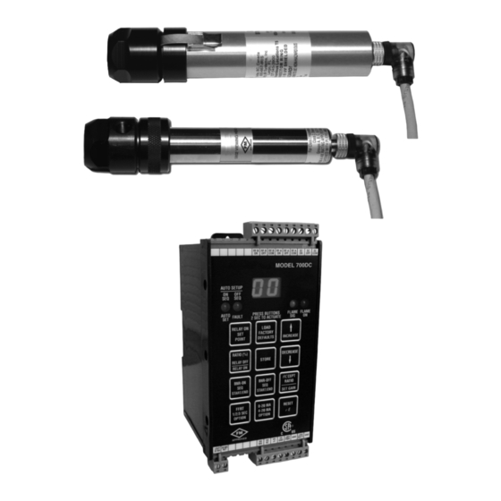
Honeywell Model 700/800 Signal
Processor and Viewing Head
APPLICATION
The Honeywell Model 700ACSP and Model 700DCSP signal
processors are single-channel, fail safe, flame monitoring
systems when used In conjunction with the S70X/S80X
viewing heads. They offer easy setup, excellent discrimination,
and high reliability.
FEATURES
Viewing heads are interchangeable between the two signal
processor models. Any viewing head in the two families will
work with any of the signal processors.
Two signal processor models are available:
• Model 700ACSP Universal 85-265 VAC powered
• Model 700DCSP 22-26VDC powered
The two Model 700 signal processors are similar, with 12
push-buttons, a two-digit numeric display, and four LED status
indicators for operator interface. The only difference between
the two is that one accepts AC power and the other accepts
DC power. Both models also accept 24VDC backup power.
Most of the signal processor connections are made through
Phoenix plug-in connectors. Communication connections are
made through modular phone jacks located at the top of the
signal processors (Fig. 7).
Both signal processor models mount on a standard 35 mm
DIN rail. They snap into place and may be released from the
rail using a flat screwdriver.
There are two types of viewing heads—IR/flicker-sensitive and
UV-sensitive—with various features offered resulting in ten
different models. See Table 1 on page 2 for details.
The S702 and S706 viewing head housings are larger in
diameter than the S80X series, are made of aluminum, and
are secured with over-center latches to their mounting blocks
(Fig. 8). In contrast, the S802 and S806 viewing head
housings are smaller in diameter and are made of stainless
steel (Fig. 9). An 800 series viewing head is secured in its
mounting block by a friction twist-lock.
The IR/flicker sensitive viewing heads have a high-pass filter
that passes flicker frequencies above 33 Hz. Some models
have a built-in high pass filter that only passes frequencies
above 155 Hz. The high frequency filter models are identified
by adding "HF" to the model number. The UV models respond
to the absolute level of UV radiation—not UV flicker—so there
is no filter option.
Application .......................................................................
Features ...........................................................................
Specifications ...................................................................
Approvals .........................................................................
Installation ........................................................................
Operation ......................................................................... 11
Modbus Communication .................................................. 16
Troubleshooting ................................................................ 19
Maintenance .................................................................... 19
Safety Manual: 700 Signal Processor .............................. 35
Safety Manual: 70X & 80X Viewing Head ........................ 38
USER MANUAL
Contents
1
1
3
3
3
Put Bar Code Here
66-2069-01
Advertisement
Table of Contents

Related Manuals for Honeywell 700


Summary of Contents for Honeywell 700
- Page 1 Honeywell Model 700/800 Signal Processor and Viewing Head USER MANUAL The two Model 700 signal processors are similar, with 12 push-buttons, a two-digit numeric display, and four LED status indicators for operator interface. The only difference between the two is that one accepts AC power and the other accepts DC power.
- Page 2 HONEYWELL MODEL 700/800 SIGNAL PROCESSOR AND VIEWING HEAD The standard electrical connector supplied with both the 700 Model 700 viewing heads are also available with a 1/2 in. pipe and 800 viewing head models has two indicator LEDs inside fitting for connecting to electrical conduits. The four it: the green LED indicates signal pulses (helpful in connecting wires exit through an epoxy seal in the 1/2 in.
-
Page 3: Specifications
CIC rating for Canada. (This rating permits use in INSTALLATION hazardous locations without a conduit.) With PF option Honeywell C330 cable or 4 conductor, 22 ga. or larger with overall braided shield, 95% coverage, or When Installing These Products... - Page 4 NOTE: Installer must be a trained, experienced flame safeguard service technician and should be In the Model 700 signal processors the flame relay (RF A/B familiar with the equipment operation and ON, OFF, COM) has two sets of FORM C (SPDT) contacts limitations and be aware of any applicable local and the self-check relay (SC ON, OFF, COM) has one set (Fig.
- Page 5 HONEYWELL MODEL 700/800 SIGNAL PROCESSOR AND VIEWING HEAD +26VDC AC POWER SUPPLY -t° .125 A APPROVED CHASSIS, 0-20 OR 4-20 MA EARTH, OR FOR INDICATOR OR SYSTEM GND INSTRUMENTATION 360 OHMS MAX TO VIEWING HEAD 24 V AC IN BACKUP BATTERY...
- Page 6 HONEYWELL MODEL 700/800 SIGNAL PROCESSOR AND VIEWING HEAD +26VDC .125 A APPROVED 0-20 OR 4-20 MA FOR INDICATOR OR INSTRUMENTATION 360 OHMS MAX TO VIEWING CHASSIS, HEAD EARTH, OR SYSTEM GND 24 V DC POWER SUPPLY BACKUP BATTERY 250 MA...
- Page 7 STANDARD "PIGTAIL" LENGTH = 10 FEET (3 METERS) GRAY CABLE WITH OVERALL SHIELD TERMINAL VH SIG BLACK VH SC WHITE VH +V GREEN VH GND SHIELD M34285A Fig. 3. Model 700 Viewing Head Cable With 1/2 in. NPT Fitting. 66-2069—01...
- Page 8 Connect the +24VDC power wire RED to its wire at both ends. designated terminal. Connection of the Honeywell type C330 cable to the viewing e. Connect the power ground wire GRN to the proper head plug is shown in Fig. 5. Cable preparation should be terminal.
- Page 9 See Fig. 4. The 700LTA (liquid tight viewing head cable With no flame signal present, the green LED will flash one adapter) is a custom part available from Honeywell; it screws pulse per second in step with the self-checking signal. The into the right-angle connector in place of the standard hex viewing head is sending back an ID pulse;...
-
Page 10: Purge Air
(160°C). Clearance Swivel mounts, small (700-1, 700-2, 700-3) - All have 1/2 in. NPTM viewing head connections on one end with varying Make sure there will be sufficient room to remove the viewing process connections including 1 in. NPTF, 1/2 in. NPTF and head housing for servicing. -
Page 11: Operation
HONEYWELL MODEL 700/800 SIGNAL PROCESSOR AND VIEWING HEAD Insulating locking coupler adapters (R-518-PT13, R-518- adapters are applicable, depending on the application. PT13L) - 1/2 in. NPTM Ultem adapters insulate the viewing Contact your distributor or the factory for assistance with fiber head electrically and thermally and are used with the R-518- optic selection and pricing. - Page 12 Adjustment can be made easier by a should be parallel to the axis of the burner and aimed at the 1/2 in. swivel joint, which Honeywell can supply if one is not root of the flame, as with the IR detector. (See previous available (refer to “Accessories”...
- Page 13 The gain of the IR and UV viewing heads can be adjusted. In addition to the information in this section, refer to Fig. 25. At power-up, the 700 signal processors display codes to tell the operator what type of viewing head and what gain is being used.
- Page 14 Relay On Setpoint Setting FFRT (Flame Failure Response Time) The two numeric digits on the Model 700 signal processor normally display the incoming count during operation; that is, To access the FFRT setpoint, press and hold the FFRT 1/2/3 the number of pulses that arrive between self-check pulses.
- Page 15 RELA Y ON and RA TIO will remain in effect. With this feature, the Model 700 signal processors set the RELAY ON SET POINT, the RATIO % (Relay Off), and the UV/ The values can be worse than just unacceptable. If the flame IR GAIN automatically.
-
Page 16: Modbus Communication
The RS-422 interface IC is a MAX489. The LOAD FACTORY DEFAULTS key again to confirm the change, ICs can drive up to quantity 32, Model 700 signal processors or press RESET to abort the change. If the factory defaults on the same bus. - Page 17 HONEYWELL MODEL 700/800 SIGNAL PROCESSOR AND VIEWING HEAD Table 4. MODBUS registers map. Register Name Description Minimum Maximum 40001 FLAMECOUNT Flame count of active viewing head (read only) 3425 40002 PROCSTATUS Processor status bitmask (read only) bit 1: flame on relay status (1=relay energized, 0=off)
- Page 18 HONEYWELL MODEL 700/800 SIGNAL PROCESSOR AND VIEWING HEAD BOILER BNR 1 BNR 2 BNR 3 BNR 4 BNR 5 BNR 6 ADDRESS BNR 1 BNR 2 BNR 3 BNR 4 ADDRESS BOILER 3 MODBUS MASTER CONTROL NOTES: A CONVERTER MAY BE NECESSARY FOR COMMUNICATION WITH THE MODBUS MASTER CONTROL.
-
Page 19: Troubleshooting
HONEYWELL MODEL 700/800 SIGNAL PROCESSOR AND VIEWING HEAD TROUBLESHOOTING Lockout or Faulty VH Indication loads factory defaults. The RELAY ON SETPOINT is set to 31. Since the flame count cannot go this high, the flame relay If the viewing head produces any pulses during the last one cannot be energized. - Page 20 HONEYWELL MODEL 700/800 SIGNAL PROCESSOR AND VIEWING HEAD 1/2 (13) 14 NPT FOR SIGHTING PIPE 1/2 (13) 14 NPT FOR SIGHTING PIPE HEX 1-1/2 (38) ACROSS FLATS HEX 1-1/2 (38) ACROSS FLATS 1-49/64 (45) DIA MOUNTING BLOCK 1-49/64 (45) DIA MOUNTING BLOCK...
- Page 21 HONEYWELL MODEL 700/800 SIGNAL PROCESSOR AND VIEWING HEAD RELAY CONNECTIONS RS-422 WIRING 35MM DIN RAIL 5-1/2 (139) APPROVED DIN RAIL RELEASE 2-29/32 (74) 3-1/4 (83) M34584 Fig. 10. Model 700DCSP Signal Processor. 66-2069—01...
- Page 22 HONEYWELL MODEL 700/800 SIGNAL PROCESSOR AND VIEWING HEAD RELAY CONNECTIONS RS-422 WIRING MODEL 700AC 35MM DIN RAIL 5-1/2 (139) APPROVED DIN RAIL RELEASE 2-29/32 (74) 3-1/4 (83) M34851 Fig. 11. Model 700ACSP Signal Processor. 66-2069—01...
- Page 23 HONEYWELL MODEL 700/800 SIGNAL PROCESSOR AND VIEWING HEAD BURNER FRONT PLATE 1 (25) NPT NIPPLE TOE S70X VIEWING HEAD 1/4 (6) NPT PURGE 700-1 SWIVEL MOUNT CONNECTION QUICK DISCONNECT CABLE CONNECTION (SUPPLIED) M34537 Fig. 12. Viewing Head Mounting Example. BURNER FRONT PLATE...
- Page 24 HONEYWELL MODEL 700/800 SIGNAL PROCESSOR AND VIEWING HEAD HIGH FREQUENCY FLICKER ZONE DETECTOR IN GOOD SIGHTING POSITION (PARALLEL SIGHTING) BURNER NOZZLE CENTERLINE DETECTOR IN POOR SIGHTING POSITION LOW FREQUENCY FLICKER ZONE M33285 Fig. 14. IR Viewing Head Location UV RADIATION...
- Page 25 HONEYWELL MODEL 700/800 SIGNAL PROCESSOR AND VIEWING HEAD NO. 1 FLAME NO. 2 FLAME ENVELOPE ENVELOPE VIEWING HEAD VIEWING HEAD BURNER NOZZLE NO. 1 BURNER NOZZLE NO. 2 HIGH FREQUENCY LOW FREQUENCY HIGH FREQUENCY ZONE IR ZONE IR ZONE (LESS THAN 36Hz) M33287 Fig.
- Page 26 HONEYWELL MODEL 700/800 SIGNAL PROCESSOR AND VIEWING HEAD RESTORING DEFAULT VALUES LOAD PRESS LOAD FACTORY DEFAULTS FACTORY FOR 2 SECONDS DEFAULTS 2 SECS DISPLAY SHOWS ‘PL’, IS THE PANEL LOCKED? MEANING THE PANEL IS LOCKED NORMAL OPERATION IS THE AUTO SET DISPLAY SHOWS ‘CF’,...
- Page 27 HONEYWELL MODEL 700/800 SIGNAL PROCESSOR AND VIEWING HEAD AUTO SETUP BNR-ON PRESS BNR-ON SEQ FOR 2 SECONDS START/END 2 SECS DISPLAY SHOWS ‘PL’ IS THE PANEL LOCKED? UNTIL KEY RELEASED IS THE AUTO SET DISPLAY SHOWS ‘CF’, LIGHT LIT? MEANING CONFIRM...
- Page 28 HONEYWELL MODEL 700/800 SIGNAL PROCESSOR AND VIEWING HEAD NOTE: AUTO SETUP - PAGE 2 (CONTINUED) PRESS RESET AT ANY TIME RESET DURING THIS PROCEDURE TO CANCEL AUTO SETUP DISPLAY BEGINS COUNTING DOWN FROM 59 SECONDS BNR-ON PRESS BNR-ON SEQ AGAIN TO END TAKING BURNER...
- Page 29 HONEYWELL MODEL 700/800 SIGNAL PROCESSOR AND VIEWING HEAD NOTE: AUTO SETUP - PAGE 3 (CONTINUED) PRESS RESET AT ANY TIME RESET DURING THIS PROCEDURE TO CANCEL AUTO SETUP IS THE AUTO SETUP RATIO MAY BE ACCEPTABLE RATIO MARGINAL? 71% < RATIO < 81% DISPLAY ALTERNATES SHOWING ‘AC’...
- Page 30 HONEYWELL MODEL 700/800 SIGNAL PROCESSOR AND VIEWING HEAD SETTING RELAY ON VALUE RELAY ON PRESS RELAY ON SET POINT DISPLAY SHOWS CURRENT FOR 2 SECONDS RELAY SETTING POINT 2 SECS INCREASE USE INCREASE OR DECREASE KEYS TO ADJUST SETTING DECREASE DISPLAY SHOWS ‘PL’...
- Page 31 HONEYWELL MODEL 700/800 SIGNAL PROCESSOR AND VIEWING HEAD SETTING RATIO PERCENTAGE RATIO (%) PRESS, RATIO (%), DISPLAY SHOWS CURRENT RATIO OFF FOR 2 SECONDS RATIO SETTING IN PERCENT RATIO ON 2 SECS INCREASE USE INCREASE OR DECREASE KEYS TO ADJUST SETTING DECREASE DISPLAY SHOWS ‘PL’,...
- Page 32 HONEYWELL MODEL 700/800 SIGNAL PROCESSOR AND VIEWING HEAD SETTING FLAME FAILURE RESPONSE TIME (FFRT) FFRT PRESS, FFRT, DISPLAY SHOWS CURRENT 1/2/3 SEC FOR 2 SECONDS SETTING IN SECONDS OPTION 2 SECS INCREASE USE INCREASE OR DECREASE KEYS TO ADJUST SETTING DECREASE DISPLAY SHOWS ‘PL’,...
- Page 33 HONEYWELL MODEL 700/800 SIGNAL PROCESSOR AND VIEWING HEAD SETTING ANALOG OUTPUT LEVELS (0-20/4-20 mA) 0-20 mA PRESS, 0-20 / 4-20 mA OPTION, DISPLAY SHOWS: 4-20 mA FOR 2 SECONDS ‘02’ FOR 0-20 mA OPTION ‘42’ FOR 4-20 mA 2 SECS...
- Page 34 HONEYWELL MODEL 700/800 SIGNAL PROCESSOR AND VIEWING HEAD SETTING VIEWING HEAD GAIN ACCEPT PRESS ACCEPT RATIO / SET GAIN RATIO DISPLAY SHOWS CURRENT FOR 2 SECONDS GAIN SETTING SET GAIN 2 SECS INCREASE USE INCREASE OR DECREASE KEYS TO ADJUST SETTING DECREASE DISPLAY SHOWS ‘PL’...
-
Page 35: Safety Manual: 700 Signal Processor
System Architecture Specific configuration of hardware and software elements in a system. (Average Probability Average Probability of Failure on Demand. In this case, regarding the 700 Signal Processor. of Failure on Demand) FIT (Failures in Time) A unit of measurement representing one failure per billion hours. 1,000,000,000 hours is approximately 114,155.25 years. - Page 36 HONEYWELL MODEL 700/800 SIGNAL PROCESSOR AND VIEWING HEAD Safety Function of the 700 The safety function of the 700 signal processor consists of a open, unless the contacts of the Flame Relay are welded Flame Relay which comprises its safety function and behaves...
- Page 37 HONEYWELL MODEL 700/800 SIGNAL PROCESSOR AND VIEWING HEAD 700 DC PFD VS TIME 4.00E 3.50E 3.00E 2.50E 2.00E 1.50E 1.00E 5.00E 0.00E TIME (YEARS) M35038 Fig. 27. Dependence of the PFD on the proof test interval for 700DC. 700AC or 700DC Signal Processor Proof Test Procedure Equipment 3.
-
Page 38: Safety Manual: 70X & 80X Viewing Head
HONEYWELL MODEL 700/800 SIGNAL PROCESSOR AND VIEWING HEAD SAFETY MANUAL: 70X & 80X VIEWING HEAD 702, 706, 802, AND 806 Product Declaration FIT FOR USE IN A LOW DEMAND SAFETY APPLICATION. Models: 702, 702-PF, 702-HF, 702-HF-PF, 706, 706-PF, 802, 802-HF, 806 λ... - Page 39 HONEYWELL MODEL 700/800 SIGNAL PROCESSOR AND VIEWING HEAD Safety Function of the 702, 706, 802, 70x and 80x Viewing Head Proof Test and 806 Interval The 702, 706, 802, and 806 viewing heads do not have a The proof test must be conducted every 1 to 5 years. This safety function.
- Page 40 HONEYWELL MODEL 700/800 SIGNAL PROCESSOR AND VIEWING HEAD 70x and 80x Viewing Head Proof Test Procedure Equipment 1. Apply power to the signal processor, fully illuminate the • Powered compatible signal processor* correctly connected to a 702, 706, 802, or 806 viewing head viewing head with the light source, and ensure that a •...