HP XP P9500 Owner's Manual
High capacity high performance disk array
Hide thumbs
Also See for XP P9500:
- Software user's manual (608 pages) ,
- Reference manual (395 pages) ,
- Manual (348 pages)
Table of Contents
Advertisement
Quick Links
HP XP P9500 Owner Guide
Abstract
This guide describes the operation of the HP XP P9500 disk array. Topics include a description of the disk array hardware,
instructions on how to manage the disk array, descriptions of the disk array control panel and LED indicators, troubleshooting,
and regulatory statements. The intended audience is a storage system administrator or authorized service provider with
independent knowledge of the HP XP P9500 disk array and the HP Remote Web Console.
HP Part Number: AV400-96588
Published: July 2013
Edition: Ninth
Advertisement
Table of Contents

Related Manuals for HP XP P9500


Summary of Contents for HP XP P9500
- Page 1 Abstract This guide describes the operation of the HP XP P9500 disk array. Topics include a description of the disk array hardware, instructions on how to manage the disk array, descriptions of the disk array control panel and LED indicators, troubleshooting, and regulatory statements.
- Page 2 © Copyright 2010, 2013 Hewlett-Packard Development Company, L.P. The information contained herein is subject to change without notice. The only warranties for HP products and services are set forth in the express warranty statements accompanying such products and services. Nothing herein should be construed as constituting an additional warranty. HP shall not be liable for technical or editorial errors or omissions contained herein.
-
Page 3: Table Of Contents
Contents 1 Introduction....................6 P9500 overview........................6 Hardware overview........................6 Controller chassis.........................7 Drive chassis........................8 Features..........................9 Scalability...........................9 High performance......................10 High capacity........................10 Connectivity........................11 P9500.........................11 Remote Web Console....................11 High reliability........................11 Non disruptive service and upgrades..................11 Economical and quiet......................11 Specifications.........................12 Software features and functions....................13 2 Functional and operational characteristics............17 System architecture overview....................17 Hardware architecture......................17 RAID implementation overview....................17... - Page 4 5 Troubleshooting..................70 Solving problems........................70 Service information messages....................70 C-Track..........................71 Insight Remote Support......................71 Failure detection and reporting process..................72 6 Support and other resources..............74 Contacting HP........................74 Subscription service......................74 Documentation feedback....................74 Related information.........................74 HP websites........................74 Conventions for storage capacity values..................75 Typographic conventions......................75 Rack stability..........................76 A Comparing the XP24000/XP20000 Disk Array and P9500 ......77...
- Page 5 Japanese VCCI-A notice......................87 Japanese VCCI-B notice......................87 Japanese VCCI marking.....................87 Japanese power cord statement...................87 Korean notices........................87 Class A equipment......................87 Class B equipment......................88 Taiwanese notices........................88 BSMI Class A notice......................88 Taiwan battery recycle statement..................88 Turkish recycling notice......................88 Laser compliance notices......................89 English laser notice......................89 Dutch laser notice......................89 French laser notice......................89 German laser notice......................90...
-
Page 6: Introduction
HP 19 inch racks. A basic P9500 disk array is a control rack (Rack- 00) that contains a controller chassis and two drive chassis (factory designation DKU). -
Page 7: Controller Chassis
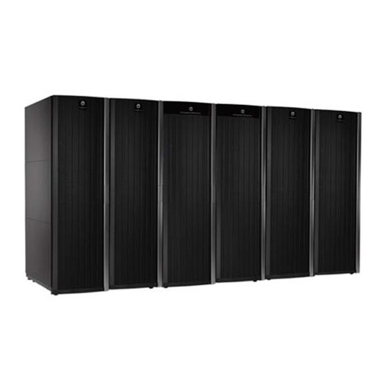
The following sections provide descriptions and illustrations of the P9500 disk array and its components. Figure 1 P9500 disk array NOTE: Each Rack is 600mm wide without side covers. Add 5mm to each end of entire assembly for each side cover. Controller chassis The controller chassis (factory designation DKC) includes the logical components, memory, disk drive interfaces, and host interfaces. -
Page 8: Drive Chassis
the rack because it is the heavier of the two units. If a system has two SVPs, both SVPs are mounted in controller chassis #0. The following illustration shows the locations of the components in the controller chassis. The controller chassis is described in more detail in “System components”... -
Page 9: Features
Figure 3 Disk Unit Features This section describes the main features of the P9500 disk array. Scalability The P9500 disk array is highly scalable and can be configured in several ways as needed to meet customer requirements: The minimum configuration is a single rack containing one controller chassis and two drive chassis. -
Page 10: High Performance
Figure 4 Example P9500 disk array configurations In addition to the number of disk drives, the system can be configured with disk drives of different capacities and speeds, varying numbers of CHAs and DKAs, and varying cache capacities, as follows: Two to six CHAs (each is a pair of boards). -
Page 11: Connectivity
The required features for the Remote Web Console computer include operating system, available disk space, screen resolution, CD drive, network connection, USB port, CPU, memory, browser, Flash, and Java environment. These features are described in Chapter 1 of the HP XP P9000 Remote Web Console User Guide. -
Page 12: Specifications
generates less heat, the fan speed is reduced, saving energy and reducing the noise level of the system. When the disk array is in standby mode, the disk drives spin down and the controller and drive chassis use significantly less power. For example, a system that consumes 100 amps during normal operation, uses only 70 amps while in standby mode. -
Page 13: Software Features And Functions
The P9500 disk array provides advanced software features and functions that increase data accessibility and deliver enterprise wide coverage of online data copy/relocation, data access/protection, and storage resource management. HP software products and solutions provide a full set of industry leading copy, availability, resource management, and exchange software to support business continuity, database backup and restore, application testing, and data mining. - Page 14 Table 4 Performance management features and functions Feature Description Cache Residency Cache Residency locks and unlocks data into the cache to optimize access to the most frequently used data. It makes data from specific logical units resident in a cache, making all data accesses become cache hits.
- Page 15 Web Console computer. SNMP Agent Provides support for SNMP monitoring and management. Includes HP specific MIBs and enables SNMP based reporting on status and alerts. SNMP agent on the SVP gathers usage and error information and transfers the information to the SNMP manager on the host.
- Page 16 RAID Manager On open systems, performs various functions, including data replication and data protection operations by issuing commands from the host to the HP disk arrays. The RAID Manager software supports scripting and provides failover and mutual hot standby functionality in cooperation with host failover products.
-
Page 17: Functional And Operational Characteristics
2 Functional and operational characteristics System architecture overview This section briefly describes the architecture of the P9500 disk array. Hardware architecture The basic system architecture is shown in the following diagram. Figure 5 P9500 architecture overview The system consists of two main hardware assemblies: A controller chassis that contains the logic and processing components A drive chassis that contains the disk drives or solid state drives. - Page 18 RAID1 option can be ideal for workloads with low cache hit ratios. NOTE: When configuring RAID1 (4D+4D), HP recommends that both RAID1 (2D+2D) groups within a RAID1 (4D+4D) group be configured under the same DKA pair. Figure 6 Sample RAID1 2D + 2D layout RAID5.
-
Page 19: Sequential Data Striping
Figure 7 Sample RAID5 3D + 1P layout (data plus parity stripe) RAID6. A RAID6 array group consists of eight data drives (6D+2P). The data is written across the eight drives in a stripe that has six data chunks and two parity chunks. Each chunk contains either eight logical tracks (mainframe) or 768 logical blocks (open). -
Page 20: Cu Images, Lvis, And Logical Units
Figure 8 LDEV striping across 2 RAID5 (7D+1P) array groups Figure 9 LDEV striping across 4 RAID5 (7D+1P) array groups All data drives and device emulation types are supported for LDEV striping. LDEV striping can be used in combination with all P9500 data management functions. CU Images, LVIs, and Logical Units This section provides information about control unit images, logical volume images, and logical units. -
Page 21: Logical Volume Images
Virtual LVI or LUSE, users can concatenate multiple logical units into large volumes. For further information on VLL and Virtual LVI, see the HP XP P9000 Performance for Open and Mainframe Systems User Guide and the HP XP P9000 Provisioning for Open Systems User Guide Mainframe operations This section provides high level descriptions of mainframe compatibility, support, and configuration. -
Page 22: Mainframe Operating System Support
At installation, the modes are set to their default values, as shown in the following table. Be sure to discuss these settings with HP Technical Support. The system option modes can only be changed by HP. - Page 23 Table 1 1 System option modes Mode Category Description Default MCU/RCU Public R-VOL read only function. (Optional) Common Regarding the correction copy or the drive copy, in case ECCs/LRC PINs are set on the track of copy source HDD, mode 22 can be used to interrupt the copy processing (default) or to create ECCs/LRC PINs on the track of copy target HDD to continue the processing.
- Page 24 Table 1 1 System option modes (continued) Mode Category Description Default MCU/RCU Pair status: Duplex/Pending A pair whose RCU# is identical to the RCU for which the Freeze command is specified. Continuous Access Notes: MCU/RCU (cont) Synchronous Z When all the following conditions are met, set Mode 64=ON. When all the following conditions are met, set Mode 64=ON.
- Page 25 Table 1 1 System option modes (continued) Mode Category Description Default MCU/RCU If you select an incorrect port while the mode is set to ON, and if ESTPATH is executed when no logic path exists, the port is switched to RCP.. Set this mode to OFF before using TPC-R (IBM software for disaster recovery).
- Page 26 Table 1 1 System option modes (continued) Mode Category Description Default MCU/RCU Notes: For more details about mode 269, see worksheet "Mode269 detail for RAID700". Mode 269 is effective only when using the SVP to format the CVS. Open Tru64 (Host Mode 07) and OpenVMS (Host Mode 05) Caution: Host offline: Required Issuing OLS when Switching Port MCU/RCU...
- Page 27 Table 1 1 System option modes (continued) Mode Category Description Default MCU/RCU Continuous Access Mode 448 = ON: (Enabled) Journal If the SVP detects a blocked path, the SVP assumes that an error Continuous Access occurred, and then immediately splits (suspends) the mirror. Journal Z Mode 448 = OFF: (Disabled) If the SVP detects a blocked path and the path does not recover...
- Page 28 Table 1 1 System option modes (continued) Mode Category Description Default MCU/RCU External Storage High Speed LDEV Format for External Volumes MCU/RCU Mode 457 = ON: The high speed LDEV format for external volumes is available by setting system option mode 457 to ON.
- Page 29 Table 1 1 System option modes (continued) Mode Category Description Default MCU/RCU Snapshot, Auto Business Copy, Business Copy Z, Compatible FlashCopy, LUN, External Snapshot, Auto LUN, External Storage Storage Mode 467 = ON: Copy overload prevention. Copy processing stops when the percentage of “dirty” data reaches 60% or higher. When the percentage falls below 60%, copy processing restarts.
- Page 30 Table 1 1 System option modes (continued) Mode Category Description Default MCU/RCU - Initial copy operation is prioritized over update I/O. Therefore, the processing speed of the update I/O slows down by about 15?s per command. 3. If this mode is set to ON, the processing speed of update I/O slows down by about 15?s per command, version downgrade is disabled, and Take Over is not available.
- Page 31 Table 1 1 System option modes (continued) Mode Category Description Default MCU/RCU Note: 1. Make sure to apply mode 491 when the performance of Business Copy/ Business Copy Z/ ShadowImage FCv1 is considered to be important. 2. Make sure not to apply the mode when the host I/O performance is considered to be important.
- Page 32 Table 1 1 System option modes (continued) Mode Category Description Default MCU/RCU Manager or Storage Navigator may show earlier time than the time showed when the pair was in the Duplex state. Open and When PIN data is generated, the SIM currently stored in SVP is MCU/RCU Mainframe reported to the host.
- Page 33 Table 1 1 System option modes (continued) Mode Category Description Default MCU/RCU Notes: 1. When DKC emulation type is 2105/2107, this mode is applied in the case where pair creation in Cnt Ac-S Z – BC Z cascading configuration in the ICKDSF environment fails with the following message output.
- Page 34 Table 1 1 System option modes (continued) Mode Category Description Default MCU/RCU Mode 676 = OFF (default): An audit log is not stored onto the system disk. This mode is also enabled/disabled by enabling/disabling Audit Log Buffer on the [Audit Log Setting...] window, which can be opened by selecting [Settings] ->...
- Page 35 Table 1 1 System option modes (continued) Mode Category Description Default MCU/RCU Read JNL or JNL Restore is not prevented when the Write Pending rate on RCU exceeds 60% (the same as before). Notes: This mode can be set online. This mode should be set per customer’s requests.
- Page 36 Table 1 1 System option modes (continued) Mode Category Description Default MCU/RCU b. An external volume to which Nondisruptive Migration (NDM) attribute is set exists. Open and To reduce the chance of MIH, this option can reduce the priority Mainframe of BC, VM, CoW Snapshot, Flash Copy or Resync copy internal IO requests so that host IO has a higher priority.
- Page 37 Table 1 1 System option modes (continued) Mode Category Description Default MCU/RCU When Not Ready is returned, the external path is blocked and the path status can be automatically recovered (Not Ready blockade). Note that the two behaviors, automatic recovery and block, may be repeated.
- Page 38 Table 1 1 System option modes (continued) Mode Category Description Default MCU/RCU page allocation is not provided at a time when the HDP pool is full. (Not to set in the case of Read request.) Mode 729 = OFF (default): Not to set the Protect attribute for the target DP-VOL using Data Ret, when any write operation is requested to the area where the page allocation is not provided at a time when HDP pool is full.
- Page 39 Table 1 1 System option modes (continued) Mode Category Description Default MCU/RCU This option is turned ON to prevent the write I/O operation from being unavailable due to pool full. If the exceeding pool threshold SIM occurs frequently, other SIMs may not be reported. Though turning on this option can increase the warning effect, if measures such as adding a pool fail to be done in time so that the pool becomes full, MODE 729 can be used to prevent...
- Page 40 Table 1 1 System option modes (continued) Mode Category Description Default MCU/RCU per hour. If SSB=AD02 occurs and a path is blocked, perform Check Paths on this path again. If Check Paths is performed while Business Copy Z pair and Compatible FlashCopy Mirror pair are defined in the specified volume, the Check Paths operation is rejected with a message “605 2518”.
- Page 41 Table 1 1 System option modes (continued) Mode Category Description Default MCU/RCU The data is settled to RCU according to the time stamp that RCU has received. Notes: 1. This mode is applied under the following conditions. (1)Continuous Access Journal Z. (2) EXCTG configuration.
- Page 42 Table 1 1 System option modes (continued) Mode Category Description Default MCU/RCU Mode 776 = OFF (default): When the status of P-VOL changes to Suspend during a TC/TCA S-VOL pair suspend or deletion operation from BCM, the F/M=FB message is output to the host. Notes: 1.
- Page 43 Table 1 1 System option modes (continued) Mode Category Description Default MCU/RCU To apply the mode to TC Sync for z/OS, MCU and RCU must be RAID600 or RAID700 and micro-program must be the support version on both sides. If a failure occurs on the switched path between DKCs, Mainframe host MIH or Open server time-out may occur.
- Page 44 Table 1 1 System option modes (continued) Mode Category Description Default MCU/RCU 1. This mode is applied when - a file system using THP pool VOLs is used. - Data Retention Utility is installed. 2. Because the DRU attribute is set to Protect for the V-VOL, a read I/O is also disabled.
- Page 45 Table 1 1 System option modes (continued) Mode Category Description Default MCU/RCU LDEV format of the DP-VOL is performed with page reclamation. Mode 867 = OFF (default):LDEV format of the HDP-VOL is performed with 0 data writing. Notes: 1. This mode is applied at recovery after a pool failure. 2.
- Page 46 Table 1 1 System option modes (continued) Mode Category Description Default MCU/RCU Notes: To apply the mode, set the RMF version of mainframe to be connected to 1.12 or higher. If the OS does not use a supported version, the transfer speed cannot be displayed correctly.
- Page 47 Table 1 1 System option modes (continued) Mode Category Description Default MCU/RCU addition, the settings of SOM 897 and 898 are effective for Tire2 and Tier3. Please also see spreadsheet "SOM 897_898_901" for more details about the relations between SOM 897, 898 and 901. Smart Tiers, Smart I/O value (IOPH) can be changed as follows.
- Page 48 Table 1 1 System option modes (continued) Mode Category Description Default MCU/RCU SOM899 is OFF: I/O synchronous copy starts when the number of retries reaches half of the threshold of Auto LUN retry. Mode 900 = OFF (default): SOM899 is ON: I/O synchronous copy starts when the threshold of Volume Migration retry is exceeded.
- Page 49 Table 1 1 System option modes (continued) Mode Category Description Default MCU/RCU Continuous Access The difference in CM allocation capacity among MPBs with Journal Z different workload is large. Mode 908 = OFF (default): The difference in CM allocation capacity among MPBs with different workload is small (existing operation) Notes: 1.
- Page 50 Table 1 1 System option modes (continued) Mode Category Description Default MCU/RCU high because the migration source and target are in the same parity group or external volume group. When pool shrink is performed per pool VOL from a parity group with multiple pool VOLs defined (or from an external volume group) while the mode is set to ON, the pool shrink takes longer time compared to when the mode is set to OFF.
-
Page 51: Host Modes And Host Mode Options
The host groups, host modes, and host mode options are configured using the LUN Manager software on Remote Web Console. For further information on host groups, host modes, and host mode options, see the HP XP P9000 Provisioning for Open Systems User Guide. Open systems operations This section provides high-level descriptions of OPEN systems compatibility, support, and configuration. -
Page 52: Open Systems Compatibility And Functionality
Each supported platform has a user guide that is included in the P9500 documentation set. See the HP XP P9000 Documentation Roadmap for a complete list of P9500 user guides, including the host configuration guides. -
Page 53: Remote Web Console
The HP XP P9000 SNMP Agent User Guide describes the SNMP API interface for the P9500 disk array and provides instructions for configuring and performing SNMP operations. The HP XP P9000 Provisioning for Open Systems User Guide and HP XP P9000 Volume Shredder for Open and Mainframe Systems User Guide provide instructions for configuring multiple custom volumes (logical units) under single LDEVs on the P9500 disk array. -
Page 54: System Components
(SVP) SVP to service center enables the storage system to be remotely monitored and maintained by the HP support team. This significantly increases the level of support that HP can provide to its customers. NOTE: The SVP also provides a communication hub for the 3rd and 4th Processor blade in Module-0. - Page 55 Table 14 Controller chassis (continued) Item Description Name data will not be lost and will remain protected on the Cache Backup Memory Solid States Disk drive. AC-DC power 200–220 VAC input. Provides power to the DKC in a supply redundant configuration to prevent system failure. Up to four power supplies can be used as needed to provide power to additional components.
-
Page 56: System Control Panel
Figure 12 Controller chassis rear view (minimum configuration) Item Description Item Description Power Supply (2 min, 4 max) Slots for optional Power Supply. Service Processor (optional for Module-0) Slots for Channel Adapter board. or Hub (optional for Module- 1 ) Slots for optional Disk Control Adapter or Slots for optional Express Switch Adapter. -
Page 57: Drive Chassis
Figure 13 P9500 system control panel Item Description Item Description MESSAGE - Amber LED ALARM - Red LED ON: indicates that a SIM (Message) was Indicates DC under voltage of any DKC part, DC generated from either of the clusters. Applied over current, abnormally high temperature, or that to both storage clusters. - Page 58 Figure 14 Drive chassis Item Description Item Description Fan (8 total) Fan assembly lock screw (Loosen screw to open fan door.) Power Cable HDD Power Supply The fans on the front of the unit are intake fans that pull ambient air into the unit. The fans on the rear assembly are exhaust fans that blow hot air out of the unit.
-
Page 59: Cache Memory
Figure 15 Disk chassis (fan door open) As shown in Figure 15 (page 59), the fan assemblies on both the front and rear sides of the drive chassis fold out and away from the unit to allow access to the disk drives. The three speed fans in the drive chassis are thermostatically controlled by a temperature sensor (thermistor) in the unit. -
Page 60: Memory Operation
Figure 16 Cache memory Table 15 Cache memory Item Description Item Description Micro Processor Blade Cache Memory Adapter: Includes 4 GB cache 8, 16, or 24 GB standard 32 GB SSD drives optional 1 or 2 16 GB SSD drives Micro Processor Blade cluster 0 Micro Processor Blade cluster 1 Cache cluster 0... -
Page 61: Shared Memory
The cache directory has mapping tables for the Micro Processor Blade LDEVs and the allocated cache slots in each Micro Processor Blade cache partition. NOTE: Shared Memory in the P9000 is not a separate memory module as it was in the HP XP24000/20000 disk arrays. Flash storage chassis This section includes information on the flash module drive (FMD), flash storage unit (FSU), and flash storage chassis (FSX). -
Page 62: Flash Module Unit
Figure 17 Flash Module Drive Flash module unit The flash module box (FMU) is a 2U high chassis that contains up to 12 FMDs, plus two redundant power supplies and two redundant SSW adapters. Figure 18 Flash Module Unit System components... -
Page 63: Flash Storage Chassis
NOTE: Be sure to use the same SSW jumper settings when replacing an SSW. Contact HP Technical Support before replacing a SSW. Flash storage chassis The flash storage chsssis (FBX) is a cluster of four FMUs as shown in the following illustration. There is not an actual chassis or enclosure surrounding the four FSBs, but since it takes the place of a DKU drive chassis, the cluster is referred to as a chassis for consistency. -
Page 64: Cache Memory
Cache memory Your P9000 can be configured with up to 512 GB of cache memory per controller chassis (1 TB for a two-module system). Each controller chassis can contain from two to eight cache memory adapter boards. Each board contains from 8 GB to 64 GB. Cache memory adaptor boards are installed in pairs and work together to provide cache and shared memory for the system. - Page 65 Table 19 System capacities with smart flash modules (continued) Considering hot sparing requirements 2D+2P 4D+4P 3D+1P 7D+1P 6D+2P 14+2P Usable 35.2 32.0 52.8 56.0 48.0 44.8 3.2 GB 140.8 128.0 140.8 128.0 128.0 102.4 Usable 70.4 64.0 105.6 1 12.0 96.0 89.6 Flash chassis pair max.
-
Page 66: Power On/Off Procedures
This section provides general information about power on/off procedures for the P9500 disk array. If needed, consult HP Technical Support for assistance. Power On procedures CAUTION: Only a trained HP support representative can restore power to the disk array. Prerequisites Ensure that the disk array is in standby mode. See “Standby mode” (page 66). -
Page 67: Power Off Procedures
NOTE: If the Alarm LED is also on, or if the Ready LED is not ON after 20 minutes, please contact HP Technical Support. The disk array generates a SIM that provides the status of the battery charge (see “Cache destage batteries” (page 68)). -
Page 68: Cache Destage Batteries
50%. The LEDs on the front panel of the cache boards also show the status of the batteries. Long term array storage While connected, the cache destage batteries will completely discharge in two to three weeks without power applied. If you do not use a P9500 for two weeks or more, contact HP Technical Power On/Off procedures... - Page 69 90 minutes before the cache will be protected. To prevent the batteries from discharging during long term storage, contact HP Technical Support and ask them to disconnect the battery jumpers on the cache boards. Battery backup operations...
-
Page 70: Troubleshooting
SIMs can be generated by the channel adapters and disk adapters and by the SVP. All SIMs generated by the P9500 are stored on the SVP for use by HP personnel, logged in the SYS1.LOGREC dataset of the mainframe host system, displayed by the Remote Web Console software, and reported over SNMP to the open system host. -
Page 71: C-Track
Notifications may be sent to your authorized HP Channel Partner for on-site service, if configured and available in your country. The HP Insite Remote Support products available for the P9500 disk arrays are described “P9500 disk array remote support products”... -
Page 72: Failure Detection And Reporting Process
Select Insight Remote Support from the menu on the right. Failure detection and reporting process If a failure occurs in the system, the failure is detected and reported to the system log, the SIM log, and HP technical support, as shown in “Failure reporting process” (page 73). - Page 73 Figure 22 Failure reporting process Failure detection and reporting process...
-
Page 74: Support And Other Resources
HP XP P9000 RemoteWeb Console User Guide HP XP P9000 SNMP Agent User Guide You can find these documents on the Manuals page of the HP Business Support Center website: http://www.hp.com/support/manuals In the Storage section, click Disk Storage Systems for hardware or Storage Software for software, and then select your product. -
Page 75: Conventions For Storage Capacity Values
Conventions for storage capacity values P9000 disk arrays use the following values to calculate physical storage capacity values (hard disk drives): 1 KB (kilobyte) = 1,000 bytes 1 MB (megabyte) = 1,000 bytes 1 GB (gigabyte) = 1,000... -
Page 76: Rack Stability
Table 22 Document conventions (continued) Convention Element Monospace text File and directory names System output Code Commands, their arguments, and argument values Monospace, italic text Code variables Command variables Monospace, bold text Emphasized monospace text WARNING! Indicates that failure to follow directions could result in bodily harm or death. CAUTION: Indicates that failure to follow directions could result in damage to equipment or data. -
Page 77: A Comparing The Xp24000/Xp20000 Disk Array And P9500
A Comparing the XP24000/XP20000 Disk Array and P9500 Comparison of the XP24000/XP20000 Disk Array and P9500 The P9500 includes several upgrades from the XP24000/XP20000 Disk Array as well as a number of new features. These include: High scalability. The system supports configurations of 2 1/2 disk drives in either a single or dual DKC configuration Shared processors. - Page 78 Table 24 Basic Mainframe functional differences (continued) Feature P9500 XP24000/XP20000 Disk Array Supported OS OS/390 V2/R10 or higher OS/390 V2/R10 or higher /OS V1R0 or higher z/OS V1R0 or higher z/VM V5R3 or higher z/VM V5R3 or higher z/VSE V4R1 or higher z/VSE V4R1 or higher Operation Interface ICKDSF...
- Page 79 Table 26 Functional differences - Business Copy for Open Systems (continued) Feature P9500 XP24000/XP20000 Disk Array Maximum number of CTG in 256CTG 256CTG system Maximum number of pair in one 8192 Pair 8192 Pair Saving differential bitmap Save to SSD Save to SVPSave to SYSTEM DISK Operation interface Remote Web Console...
-
Page 80: B Specifications
B Specifications Mechanical specifications The following table lists the mechanical specifications of the P9500 disk array. Table 27 P9500 mechanical specifications Dimension Single Rack Single Module Dual Module (3 racks) (6 racks) Width (inches / mm) 24.0 / 610 71.3 / 1810 142 / 3610 Depth (inches / mm) 45 / 1 145... -
Page 81: System Components Heat And Power Specifications
System components heat and power specifications Table 29 System components heat and power specifications Power Consumption Heat Output (kW) (kVA) Component Product Number HP XP P9500 Disk Array Component AV375A Flash Module Chassis 0.600 0.640 AV392A, AV393A Flash Module 0.017 0.018... -
Page 82: Ac Power - Pdu Options
Table 29 System components heat and power specifications (continued) Power Consumption Heat Output (kW) (kVA) Component Product Number HP XP P9500 Disk Array Component AV492A 200GB SAS 2.5in DP MLC SSD 0.0026 0.0028 AV493A 400GB SAS 2.5in DP MLC SSD 0.0026... -
Page 83: Environmental Specifications
PDU models can be changed in the field using offline maintenance procedures. NOTE: When ordering systems, HP does not allow mixtures of different phase PDUs in a system (even though there are no technical issues). Only upgrade orders can ship with difference phase PDUs in a system. - Page 84 Table 31 P9500 environmental specifications (continued) Item Operating Not Operating In Storage 70 to 99 Hz: 0.05 mm At the resonant frequency with the highest displacement found 99 to 300 Hz: 9.8 m/s between 3 to 100 Hz Random Vibration: 0.147 m2/s3 30 min, 5 to 100 Hz Earthquake...
-
Page 85: C Regulatory Compliance Notices
C Regulatory compliance notices This section contains regulatory notices for the HP HP P9500 Disk Array. Regulatory compliance identification numbers For the purpose of regulatory compliance certifications and identification, this product has been assigned a unique regulatory model number. The regulatory model number can be found on the product nameplate label, along with all required approval markings and information. -
Page 86: Declaration Of Conformity For Products Marked With The Fcc Logo, United States Only
off and on, the user is encouraged to try to correct the interference by one or more of the following measures: Reorient or relocate the receiving antenna. Increase the separation between the equipment and receiver. Connect the equipment into an outlet on a circuit that is different from that to which the receiver is connected. -
Page 87: Japanese Notices
This compliance is indicated by the following conformity marking placed on the product: This marking is valid for non-Telecom products and EU harmonized Telecom products (e.g., Bluetooth). Certificates can be obtained from http://www.hp.com/go/certificates. Hewlett-Packard GmbH, HQ-TRE, Herrenberger Strasse 140, 71034 Boeblingen, Germany Japanese notices... -
Page 88: Class B Equipment
Class B equipment Taiwanese notices BSMI Class A notice Taiwan battery recycle statement Turkish recycling notice Türkiye Cumhuriyeti: EEE Yönetmeliğine Uygundur Regulatory compliance notices... -
Page 89: Laser Compliance Notices
Do not operate controls, make adjustments, or perform procedures to the laser device other than those specified herein. Allow only HP Authorized Service technicians to repair the unit. The Center for Devices and Radiological Health (CDRH) of the U.S. Food and Drug Administration implemented regulations for laser products on August 2, 1976. -
Page 90: German Laser Notice
German laser notice Italian laser notice Japanese laser notice Regulatory compliance notices... -
Page 91: Spanish Laser Notice
Spanish laser notice Recycling notices English recycling notice Disposal of waste equipment by users in private household in the European Union This symbol means do not dispose of your product with your other household waste. Instead, you should protect human health and the environment by handing over your waste equipment to a designated collection point for the recycling of waste electrical and electronic equipment. -
Page 92: Bulgarian Recycling Notice
Bulgarian recycling notice Изхвърляне на отпадъчно оборудване от потребители в частни домакинства в Европейския съюз Този символ върху продукта или опаковката му показва, че продуктът не трябва да се изхвърля заедно с другите битови отпадъци. Вместо това, трябва да предпазите човешкото здраве и околната среда, като... -
Page 93: Estonian Recycling Notice
Estonian recycling notice Äravisatavate seadmete likvideerimine Euroopa Liidu eramajapidamistes See märk näitab, et seadet ei tohi visata olmeprügi hulka. Inimeste tervise ja keskkonna säästmise nimel tuleb äravisatav toode tuua elektriliste ja elektrooniliste seadmete käitlemisega egelevasse kogumispunkti. Küsimuste korral pöörduge kohaliku prügikäitlusettevõtte poole. Finnish recycling notice Kotitalousjätteiden hävittäminen Euroopan unionin alueella Tämä... -
Page 94: Greek Recycling Notice
Greek recycling notice Απόρριψη άχρηοτου εξοπλισμού από ιδιώτες χρήστες στην Ευρωπαϊκή Ένωση Αυτό το σύμβολο σημαίνει ότι δεν πρέπει να απορρίψετε το προϊόν με τα λοιπά οικιακά απορρίμματα. Αντίθετα, πρέπει να προστατέψετε την ανθρώπινη υγεία και το περιβάλλον παραδίδοντας τον άχρηστο εξοπλισμό... -
Page 95: Lithuanian Recycling Notice
Lithuanian recycling notice Nolietotu iekārtu iznīcināšanas noteikumi lietotājiem Eiropas Savienības privātajās mājsaimniecībās Šis simbols norāda, ka ierīci nedrīkst utilizēt kopā ar citiem mājsaimniecības atkritumiem. Jums jārūpējas par cilvēku veselības un vides aizsardzību, nododot lietoto aprīkojumu otrreizējai pārstrādei īpašā lietotu elektrisko un elektronisko ierīču savākšanas punktā. Lai iegūtu plašāku informāciju, lūdzu, sazinieties ar savu mājsaimniecības atkritumu likvidēšanas dienestu. -
Page 96: Slovak Recycling Notice
Slovak recycling notice Likvidácia vyradených zariadení používateľmi v domácnostiach v Európskej únii Tento symbol znamená, že tento produkt sa nemá likvidovať s ostatným domovým odpadom. Namiesto toho by ste mali chrániť ľudské zdravie a životné prostredie odovzdaním odpadového zariadenia na zbernom mieste, ktoré... -
Page 97: French Battery Notice
French battery notice German battery notice Battery replacement notices... -
Page 98: Italian Battery Notice
Italian battery notice Japanese battery notice Regulatory compliance notices... -
Page 99: Spanish Battery Notice
Spanish battery notice Battery replacement notices... -
Page 100: Glossary
HDDs (7D+1P). All RAID6 array groups are made up of eight HDDs (6D+2P). This is also known as a parity group or a RAID group. P9000 or XP Business Copy. An HP application that provides volume-level, point-in-time copies in the disk array. - Page 101 LDEVs associated with the LUN. LUSE Logical Unit Size Expansion. The LUSE feature is available when the HP StorageWorks LUN Manager product is installed, and allows a LUN, normally associated with only a single LDEV, to be associated with 1 to 36 LDEVs. Essentially, LUSE makes it possible for applications to access a single large pool of storage.
- Page 102 DRAM or EEPROM memory boards, a memory bus board, a CPU, and a battery card. SSVPMN Sub Service Processor Monitor. Service processor. A computer built into a disk array. The SVP, used only by an HP service representative, provides a direct interface to the disk array. synchronous Describes computing models that perform tasks in chronological order without interruption.
-
Page 103: Index
Japanese notices, controller, controller, components, drive, Korean notices, components controller chassis, drive chassis, laser compliance notices, configuration logical units, 20, maximum, minimum, contacting HP, mainframe, 21, controller chassis, 7, memory controller, components, 8, cache, controls shared, description, microprocessor, system, conventions document,... - Page 104 Subscriber's Choice, HP, SVP, switches control, ESW, power, symbols in text, system reliability, Taiwanese notices, technical support service locator website, technological advances, text symbols, typographic conventions, virtualization, warning rack stability, websites HP , HP Subscriber's Choice for Business, product manuals, 104 Index...