Table of Contents
Advertisement
Quick Links
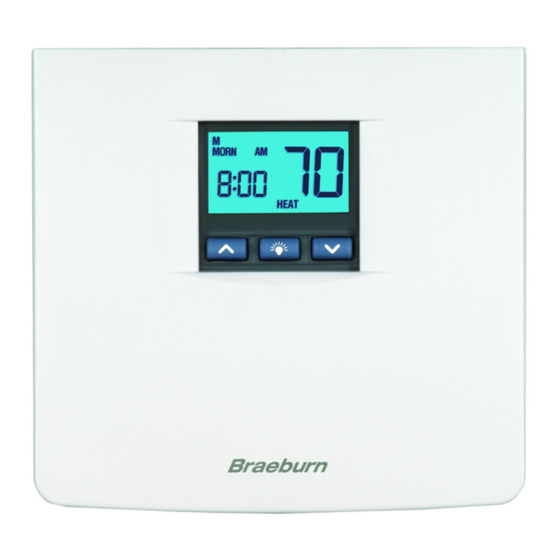
MODEL
5200
OWNERS MANUAL
Compatible with low voltage multi-stage heat
pump systems with up to two stages of heating
and two stages of cooling. Not for use on
single-stage heating or cooling systems.
READ ALL INSTRUCTIONS BEFORE PROCEEDING
YEAR
LIMITED
WARRANTY
Store this
booklet for
future reference
Braeburn Systems LLC, as an Energy Star partner
has determined that this product meets the Energy
Star Guidelines developed by the U.S. Environmental
Protection Agency & the U.S. Department of Energy
for maximum energy efficiency.
© 2004 Braeburn Systems LLC All Rights Reserved.
Premier Series
7-Day Programmable
2-Heat / 2-Cool & Heat Pump
Digital Thermostat
Pub. No. 5200-100-002
Quick Reference/Installation Guide
CONTENTS
FEATURES
1
2
SPECIFICATIONS
INSTALLATION
3
Replacing Existing Thermostat
3.1
Installing Your New Thermostat
3.2
TESTING YOUR NEW THERMOSTAT
4
PROGRAMMING
5
Default Thermostat Settings
5.1
Setting Current Time of Day and Day of Week
5.2
Setting Temperature Differential and Residual
5.3
Cooling Fan Feature
Setting First Stage Differential
5.3.1
Setting Second Stage Differential
5.3.2
Setting Residual Cooling Fan Feature
5.3.3
Setting Your Energy Saving Programs
5.4
Tips Before Starting
5.4.1
Using Quick Program Groups
5.4.2
or Individual Day Programming
Entering Your Program
5.4.3
6
ADDITIONAL OPERATION FEATURES
Review Set Temperature
6.1
Temporary Program Override
6.2
Permanent Hold (Vacation) Mode
6.3
Efficient Recovery Mode (ERM ™ )
6.4
6.5
Compressor Protection
High Temperature Safety Switch
6.6
Changing Fahrenheit (˚F) to Celsius (˚C)
6.7
Low Battery Detection and Replacement
6.8
Replacing the Back-up Batteries
6.8.1
Resetting Thermostat
6.9
6.10
Multi-Colored LED Indicators
TROUBLESHOOTING
7
WIRING DIAGRAMS
8
WARNING!
Important Safety Information
• Always turn off power to the air conditioning or heating system prior to installing,
removing, cleaning or servicing thermostat.
• Read this manual thoroughly prior to installing, programming or operating this
thermostat.
• This thermostat is designed for use with a 24 Volt AC low voltage multi-stage heat
pump system.
• Do not use this thermostat on single stage systems or other systems with
voltages higher than 30 Volt AC.
• This thermostat requires 24 Volt AC power for normal operation and control of the
heating or cooling system.
• This thermostat also requires two (2) properly installed "AA" alkaline batteries to
retain user settings and programs in the event of loss of AC Power due to power
outage or rolling blackouts.
• Wiring must conform to all building codes and ordinances as required by local
and national code authorities having jurisdiction.
• Do not short (or jumper) across terminals on the gas valve or at the heating or
cooling system control board to test the thermostat installation. This could
damage the thermostat and void the warranty.
• Do not select COOL mode of operation if the outside temperature is below 50˚ F
(10˚ C). This could possibly damage the controlled cooling system and may cause
personal injury.
• This thermostat should only be used as described in this manual. Any other use
is not recommended and will void the warranty.
1
Advertisement
Table of Contents

Related Manuals for Braeburn 5200


Summary of Contents for Braeburn 5200
- Page 1 • This thermostat should only be used as described in this manual. Any other use is not recommended and will void the warranty. Protection Agency & the U.S. Department of Energy for maximum energy efficiency. © 2004 Braeburn Systems LLC All Rights Reserved. Pub. No. 5200-100-002...
-
Page 2: Installation
FEATURES INSTALLATION cont. • Contemporary styling with large display Replacing Existing Thermostat cont. • 7 Day Programming Flexibility • AC Powered with Battery Back-up (2 AA Alkaline batteries included) 4. After labeling and removing all wires from terminals, unscrew the existing thermostat •... -
Page 3: Testing Your New Thermostat
TESTING YOUR INSTALLATION cont. NEW THERMOSTAT cont. Installing Your New Thermostat cont. 1. Place the system switch in the HEAT position. 2. Press the button on the keypad until the setpoint temperature setting is a minimum of 3 degrees Mark placement of mounting holes as appropriate and drill using a 3/16" drill bit. higher than the current room temperature. - Page 4 PROGRAMMING PROGRAMMING cont. cont. Setting Current Time of Day and Day of Week cont. Setting Temperature Differential and Residual Cooling Fan Feature cont. 2. Press the buttons to set the current hour. Setting Second Stage Differential cont. 5.3.2 3. Press DAY/TIME button again, the minute portion of the time will flash. 4.
- Page 5 PROGRAMMING PROGRAMMING cont.. cont.. Setting Your Energy Saving Programs cont.yt Setting Your Energy Saving Programs Tips Before Starting 5.4.1 Using Quick Program Groups or Individual Day Programming cont. 5.4.2 • It is important for you to set the current time of day (note AM/PM indicator in display), and the current day of Individual Days –...
-
Page 6: Additional Operation Features
ADDITIONAL PROGRAMMING OPERATION FEATURES cont.. cont.. Temporary Program Override Setting Your Energy Saving Programs cont. 1. Press and hold buttons for 3 seconds. The Entering Your Program cont. 5.4.3 entire display will flash once and the SET TEMP indicator will be flashing. Release the 3. - Page 7 ADDITIONAL ADDITIONAL OPERATION FEATURES OPERATION FEATURES cont. cont.. Compressor Protection cont. Low Battery Detection and Replacement cont. NOTE: The installer can reset the thermostat and bypass the compressor protection When this feature determines that the back-up batteries status is low, low battery indicator features by pressing the RESET button.
-
Page 8: Troubleshooting
TROUBLESHOOTING TROUBLESHOOTING cont. SYMPTOM POTENTIAL SOLUTION SYMPTOM POTENTIAL SOLUTION Thermostat does not Check to see if OFF is shown in display. This indicates that the Thermostat turns on Increase or decrease second (auxiliary) stage temperature system is turned off at the thermostat. Move the system turn on heating or second (auxiliary) differential setting as appropriate to provide the desired... -
Page 9: Wiring Diagrams
TROUBLESHOOTING WIRING DIAGRAMS cont. Carrier, Bryant, Payne, Day & Night and Reliant Typical Heat Pumps SYMPTOM POTENTIAL SOLUTION THERMOSTAT TERMINAL BLOCK LO is shown in the The temperature sensed by the thermostat is lower than the 40˚ F (5˚ C) lower limit of the thermostats display range. The display... - Page 10 WIRING DIAGRAMS WIRING DIAGRAMS cont. cont. Lennox Typical Heat Pumps (also see other Lennox diagrams) Lennox HP22 Typical Heat Pump THERMOSTAT TERMINAL BLOCK THERMOSTAT TERMINAL BLOCK R-VR Lennox HP19, HP20 Typical Heat Pumps Trane Typical Heat Pumps THERMOSTAT TERMINAL BLOCK THERMOSTAT TERMINAL BLOCK V-VR Lennox HP21...
- Page 11 WIRING DIAGRAMS cont. York E1 Series Typical Heat Pumps THERMOSTAT TERMINAL BLOCK User Supplied Jumper Braeburn Systems LLC warrants each new Braeburn thermostat YEAR against any defects that are due to faulty material or workmanship for a period of two years after the original date of LIMITED purchase by a professional service technician.