Icom IC-F3021T Instruction Manual
Vhf transceivers; uhf transceivers mdc 1200 compatible
Hide thumbs
Also See for IC-F3021T:
- Service manual (7 pages) ,
- Service manual addendum (105 pages) ,
- Instruction manual (32 pages)
Table of Contents
Advertisement
INSTRUCTION MANUAL
VHF TRANSCEIVERS
iF3021T/S
iF3023T/S
iF3026T/S
UHF TRANSCEIVERS
iF4021T/S
iF4023T/S
iF4026T/S
This device complies with Part 15 of the FCC
Rules. Operation is subject to the condition that
this device does not cause harmful interference.
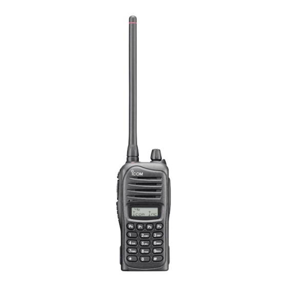
The photo shows the 10-key
version VHF transceiver.
Advertisement
Table of Contents

Related Manuals for Icom IC-F3021T


Summary of Contents for Icom IC-F3021T
- Page 1 INSTRUCTION MANUAL VHF TRANSCEIVERS iF3021T/S iF3023T/S iF3026T/S UHF TRANSCEIVERS iF4021T/S iF4023T/S iF4026T/S This device complies with Part 15 of the FCC Rules. Operation is subject to the condition that this device does not cause harmful interference. The photo shows the 10-key version VHF transceiver.
-
Page 2: Explicit Defenitions
Safe driving requires your full attention— anything less may result in an accident. Icom, Icom Inc. and the Icom logo are registered trademarks of Icom Incor- porated (Japan) in Japan, the United States, the United Kingdom, Germany,... -
Page 3: Fcc Information
CAUTION: Changes or modifications to this transceiver, not operation, or after being placed in extremely cold areas. expressly approved by Icom Inc., could void your authority to DO NOT modify the transceiver. The transceiver warranty operate this transceiver under FCC regulations. -
Page 4: Table Of Contents
TABLE OF CONTENTS 4 BATTERY CHARGING ..........16–20 IMPORTANT ................i EXPLICIT DEFENITIONS ............. i ■ Caution ...............16 PRECAUTIONS ..............i ■ Optional battery chargers ...........18 FCC INFORMATION ............ii 5 BATTERY CASE ............21 TABLE OF CONTENTS ............iii ■ Optional battery case (BP-240) ........21 1 ACCESSORIES ............1–2 6 OPTIONAL SWIVEL BELT CLIP ......22–23 ■... -
Page 5: Accessories
ACCESSORIES ■ Supplied accessories D Battery pack The following accessories are supplied with the transceiver. To attach the battery pack: Battery pack Flexible antenna Slide the battery pack in the direction of the arrow (q), then lock it with the battery release button. •... -
Page 6: Accessories
ACCESSORIES D Belt clip D Jack cover To attach the belt clip: Attach the jack cover when the optional speaker-microphone or headset is not used. q Remove the battery pack if it is attached. w Slide the belt clip in the direction of the arrow until the belt CAUTION: Use the supplied screws only. -
Page 7: Panel Description
PANEL DESCRIPTION ■ Front panel e DEALER-PROGRAMMABLE KEY [Side1] Desired function can be programmed by your dealer. (p. 5) r PTT SWITCH [PTT] Push and hold to transmit; release to receive. t DEALER-PROGRAMMABLE KEYS [Side2]/[Side3] Desired functions can be programmed independently by Speaker your dealer. -
Page 8: Function Display
PANEL DESCRIPTION ■ Function display ■ Front panel (Continued) o EXTERNAL MICROPHONE/SPEAKER JACK Connect an optional speaker-microphone or headset. NOTE: Connect or disconnect the optional equipment after the transceiver is turned OFF. Jack cover NOTE: Attach the jack cover when the optional equipment is not used. -
Page 9: Programmable Function Keys
Appears when the voice scrambler function is activated. [Side2], [Side3], [P0], [P1], [P2] and [P3] programmable function keys. u BELL INDICATOR Consult your Icom dealer or system operator for details con- Appears/blinks when the specific 2-tone code is received, cerning your transceivers programming. according to the pre-programming. - Page 10 PANEL DESCRIPTION ■ Programmable function keys (Continued) SCAN A KEY SCAN ADD/DEL (TAG) KEY ➥ This key’s operation depends on the Power ON Scan set- ➥ Push to add a channel to, or delete it from the current scan ting. list.
- Page 11 PANEL DESCRIPTION PRIO A/B KEYS C.TONE CH ENT KEY ➥ Push to select Priority A or Priority B channel. Push to select the continuous tone channel using [CH Up]/ ➥ Push and hold [Prio A (Rewrite)] or [Prio B (Rewrite)] for [CH Down] to change the tone frequency/code setting.
-
Page 12: Panel Description
PANEL DESCRIPTION ■ Programmable function keys (Continued) SIREN KEY CALL KEYS Push to emit a siren. Push to transmit a 2-tone. • Call transmission is necessary before you call another station TX CODE CHANNEL SELECT KEY depending on your signaling system. Push to enter the ID code channel selection mode directly. -
Page 13: Basic Operation
BASIC OPERATION ■ Turning power ON D Battery type selection Prior to using the transceiver for the first time, the battery pack must be fully charged for optimum life and operation. The battery type must be selected according to the attaching (p. -
Page 14: Channel Selection
BASIC OPERATION ■ Channel selection ■ Call procedure Several types of channel selections are available. Methods When your system employs tone signaling (excluding CTCSS may differ according to your system set up. and DTCS), the call procedure may be necessary prior to voice transmission. -
Page 15: Receiving And Transmitting
BASIC OPERATION ■ Receiving and transmitting D Transmitting notes CAUTION: Transmitting without an antenna may damage the transceiver. See page 1 for accessory attachments. • Transmit inhibit function The transceiver has several inhibit functions which restrict Receiving: transmission under the following conditions: q Rotate [VOL] to turn the power ON. -
Page 16: D Tx Code Channel Selection
BASIC OPERATION D TX code channel selection D DTMF transmission If the transceiver has [TX Code CH Select] assigned to it, If the transceiver has [DTMF Autodial] assigned to it, the the indication can be toggled between the operating channel automatic DTMF transmission function is available. -
Page 17: User Set Mode
BASIC OPERATION ■ User Set mode ■ Stun function If the transceiver has [User Set Mode] assigned to it, you can When the specified ID, set as a stun ID or kill ID, is received, “customize” the transceiver operation to suit your preferences the stun function is activated. -
Page 18: Emergency Call
BASIC OPERATION ■ Emergency Call D NOTES When [Emergency] is pushed for the specified time period*, the emergency signal is transmitted once, or repeatedly, on Depending on the presetting, the following functions are auto- the specified emergency channel. matically activated. Ask your dealer for details. •... -
Page 19: Mdc 1200 System Operation
BASIC OPERATION ■ MDC 1200 system operation D Receiving an Emergency Call The MDC 1200 signaling system enhances your transceiver’s capabilities. It allows PTT ID*, Emergency signaling, and re- q When an emergency call is received; ceiving Radio Check. Also, the dispatcher can stun and revive •... -
Page 20: Battery Charging
Icom radios or Icom charger. Only Icom battery R DANGER! DO NOT expose the battery to rain, snow, sea- packs are tested and approved for use and charge with Icom water, or any other liquids. Never charge or use a wet battery. - Page 21 If R DANGER! NEVER charge the battery pack in areas with any of these conditions occur, contact your Icom dealer or extremely high temperatures, such as near fires or stoves, distributor.
-
Page 22: Optional Battery Chargers
BATTERY CHARGING ■ Optional battery chargers D Regular charging with the BC-171 D Rapid charging with the BC-160 The optional BC-171 provides regular charging of the Li-Ion The optional BC-160 provides rapid charging of the Li-Ion battery pack. battery pack. •... - Page 23 BATTERY CHARGING D AD-106 installation D Rapid charging with the BC-119N+AD-106 The AD-106 must be installed into the The optional BC-119N provides rapid charging of the Li-Ion charger adapter BC-119N or BC-121N before battery charging. battery pack. The following items are additionally required. •...
-
Page 24: Battery Charging
BATTERY CHARGING D Rapid charging with the BC-121N+AD-106 The optional BC-121N allows up to 6 Li-Ion battery packs to CAUTION: be charged simultaneously. The following items are addition- When using the OPC-515L/OPC-656 DC power cable ally required. NEVER reverse the polarity when connecting the OPC- •... -
Page 25: Battery Case
BATTERY CASE ■ Optional battery case (BP-240) When using the optional battery case, install 6 × AAA (LR03) Fig.1 size alkaline batteries as illustrated at right. BP-240 q Unhook the battery cover release hook (q), and open the cover in the direction of the arrow (w). (Fig.1) w Then, install 6 ×... -
Page 26: Optional Swivel Belt Clip
OPTIONAL SWIVEL BELT CLIP ■ MB-93 contents r Clip the belt clip to a part of your belt. And insert the transceiver into the belt clip until the base clip inserted fully into the groove. Qty. q Belt clip ................1 w Base clip .................1 ■... -
Page 27: Detaching
OPTIONAL SWIVEL BELT CLIP ■ Detaching w Remove the battery pack if it is attached. (p. 1) q Turn the transceiver upside down in the direction of the arrow and pull out from the belt clip. e Pinch the clip (q), and slide the base clip in the direction of the arrow (w). -
Page 28: Options
OPTIONS D BATTERY PACK • BC-160 + BC-145S desktop charger ac adapter For rapid charging of battery packs. An AC adapter is sup- Battery pack Voltage Capacity Battery life* plied with the charger depending on versions. 950 mAh (min.) Charging time: Approximately 3.5 hours when BP-232H is BP-230N 7.4 V 7.35 hrs. -
Page 29: Options
Icom transceiver. Provides measure of safety when working in a hazardous Icom is not responsible for the destruction or damage to an environment, etc. Icom transceiver in the event the Icom transceiver is used with equipment that is not manufactured or approved by Icom. -
Page 30: Safety Training Information
This radio has been tested and complies with the FCC RF exposure FCC RF exposure compliance requirements to be exceeded. The limits for “Occupational Use Only”. In addition, your Icom radio com- radio is transmitting when the TX indicator lights red. You can plies with the following Standards and Guidelines with regard to RF cause the radio to transmit by pressing the “PTT”... -
Page 31: Safety Training Information
• Supplément C, édition 97-01, du Bulletin OET n° 65 de la FCC, Icom illustrée à la p. 25, lorsque vous attachez la radio à votre ceinture, «Evaluating Compliance with FCC Guidelines for Human Expo- ou à... - Page 32 A-6506D-1EX-i Printed in Japan © 2006–2012 Icom Inc. 1-1-32 Kamiminami, Hirano-ku, Osaka 547-0003, Japan Printed on recycled paper with soy ink.