Sony DWZB70HL Operating Instructions Manual
Digital wireless package
Hide thumbs
Also See for DWZB70HL:
- Brochure (8 pages) ,
- Product manual (2 pages) ,
- Quick start manual (2 pages)
Table of Contents
Advertisement
Quick Links
Advertisement
Table of Contents

Related Manuals for Sony DWZB70HL


Summary of Contents for Sony DWZB70HL
-
Page 1: Operating Instructions
4-460-562-11 (1) Digital Wireless Package Operating Instructions Before operating the unit, please read this manual thoroughly and retain it for future reference. Please read this manual together with the manual supplied with the BC-DWZ1. DWZ-M70/B70HL © 2012 Sony Corporation... - Page 2 – Consult the dealer or an experienced radio/TV technician for help. Voor de klanten in Europa Hierbij verklaart Sony Corporation dat het toestel ZTX-M02RC/ You are cautioned that any changes or modifications not expressly B02RC in overeenstemming is met de essentiële eisen en de andere approved in this manual could void your authority to operate this relevante bepalingen van richtlijn 1999/5/EG.
- Page 3 Eυρώπης Sony Corporation izjavlja, da je ta ZTX-M02RC/B02RC v skladu z bistvenimi zahtevami in ostalimi relevantnimi določili Με την παρ ύσα η Sony Corporation δηλώνει τι direktive 1999/5/ES. ZTX-M02RC/B02RC συμμ ρφώνεται πρ ς της Za podrobnosti vas naprošamo, če pogledate na URL: υσιώδεις...
- Page 4 If you have any questions about this product, you may call ; Eυρώπης Sony Customer Information Service Center 1-800-222-7669 or Με την παρ ύσα η Sony Corporation δηλώνει τι ZRX- http://www.sony.com/ HR70 συμμ ρφώνεται πρ ς της υσιώδεις απαιτήσεις και τις λ ιπές σ ετικές διατά εις της δηγίας 1999/5/ΕΚ.
- Page 5 • Do not install near any heat sources such as radiators, heat registers, stoves, or other apparatus (including amplifiers) that This product has been manufactured by or on behalf of Sony produce heat. Corporation, 1-7-1 Konan Minato-ku Tokyo, 108-0075 Japan.
-
Page 6: Table Of Contents
Table of Contents Package Contents ........7 DWZ-M70 ............ 7 DWZ-B70HL..........7 Features ............8 DWZ-M70 ............ 8 DWZ-B70HL..........8 ZTX-M02RC ..........8 ZTX-B02RC ..........8 ZRX-HR70 ........... 8 Parts Identification ........9 DWZ-M70 ............ 9 DWZ-B70HL..........11 Power Supply..........12 Inserting Batteries........12 Attaching the Supplied Accessories ..13 Attaching the Supplied Accessories to the Handheld Microphone... -
Page 7: Package Contents
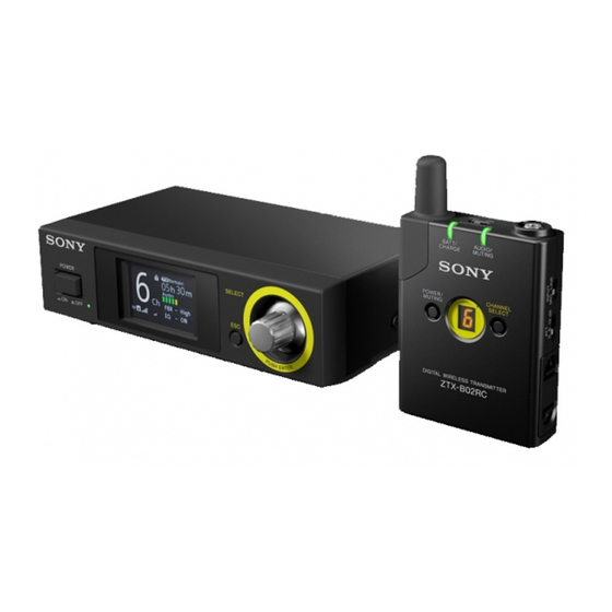
Package Contents This manual contains information on the Sony DWZ-M70/B70HL Digital Wireless Packages. The contents of each package are as follows. DWZ-M70 This set includes a handheld microphone (transmitter: ZTX-M02RC) and a half-rack receiver (receiver: ZRX-HR70). ZTX-M02RC handheld ZRX-HR70 half-rack... -
Page 8: Features
High reliability By allowing you to select from two RF modes based on A half-rack receiver equipped with large-screen high- your intended use and incorporating Sony’s unique data resolution color LCD that combines high-functionality processing technology, the system provides highly- with simple operability. -
Page 9: Parts Identification
e Antenna cover Parts Identification Contains the antenna. Caution Do not squeeze the antenna cover. Doing so will weaken DWZ-M70 the signal that is transmitted, decreasing the transmission range. Handheld microphone (transmitter: ZTX- f ATT (attenuator) switch M02RC) Set the attenuation level based on the sound volume. Top (when microphone unit is removed) Attenuation level (dB) When to use Standard switch position... - Page 10 b POWER indicator Rear Lights when the unit is turned on. c Display a ANTENNA a/b connector (BNC type) Connect the supplied antenna here. b UNBALANCED OUTPUT AUX/TUNER (external audio output) connector (headphone Displays setting configurations and other information. jack) Connect monitoring equipment and similar peripheral A Receiving channel indicator devices here.
-
Page 11: Dwz-B70Hl
f Cable clamp e AUDIO/MUTING indicator Secures the cable of the supplied AC adapter. Indicates the input level of the audio signal and the status of the muting function. g DC IN 12V (power input) connector Indicator Status Connect the supplied AC adapter here. Lit (green) Audio input present Lit (red) -
Page 12: Power Supply
The display disappears after about 10 seconds. You can Power Supply display it again by pressing the channel selection button. For details on the channel display, see “Channel Display” (page 18). This section describes the power supply for each device. k CHANNEL SELECT button For details on how to insert batteries, see “Inserting Allows you to select the RF mode and the transmitting... -
Page 13: Attaching The Supplied Accessories
Insert two new LR6 (size AA) batteries while making Attaching the Supplied sure the polarities are correct. Accessories This section describes how to attach the supplied accessories to each unit. Attaching the Supplied Accessories to the Handheld Microphone (ZTX- Close the grip and turn it in the reverse direction in the step 2 above. -
Page 14: Attaching The Supplied Accessories To The Half-Rack Receiver (Zrx-Hr70)
To attach to a belt Attaching the Supplied Accessories to the Half-Rack Receiver (ZRX- HR70) Attaching the antenna Insert the supplied antenna into the ANTENNA a/b connector at the rear of the receiver and turn it. Slide the belt into the belt clip on the unit completely, and make sure it is secure. -
Page 15: Receiver Settings
Attaching the headband and the cord clip Receiver Settings Use the rotary encoder and the ESC button to configure settings on the ZRX-HR70 half-rack receiver. Perform setting operations as follows. Confirm: Press the rotary encoder. Move cursor: Turn the rotary encoder. Cancel: Press the ESC button. - Page 16 Specify the channel using one of the following Select the effect level you want to use. methods. Select [Set]. Note This completes the configuration, and the main screen appears again. When configuring settings using method A or B, turn off all transmitters beforehand. Configuring the feedback reducer ASelect [Best Channel Selection] function for connectors...
-
Page 17: Transmitter Settings
Select the frequency for which you want to adjust the Transmitter Settings level, and adjust the setting. Select [Set]. The setting value is saved. Configuring the Transmitting To cancel the setting, press the ESC button. Channel Settings Configuring the transmitter muting Two RF modes (channel modes), wide band and narrow function for the output connectors band, are available on the DWZ. -
Page 18: Channel Display
Press and hold the channel selection button to apply Enabling Encrypted the channel selection. Transmission Caution If you change the channel setting on the transmitter, be sure to change the channel setting on the receiver to the Encrypted transmission will only be enabled on same channel. - Page 19 Disabling encrypted transmission Set the ENCRYPTION switch on the transmitter to the OFF position. In the [Setup] screen of the receiver, select [Advanced Settings]. The [Advanced Settings] screen appears. For details on displaying the [Setup] screen, see “Displaying the settings menu” (page 15). Select [Encryption].
-
Page 20: Channel Frequency List
Channel Frequency List The frequencies used by the wide band (WIDE, channels 1 to 6) and the narrow band (NARROW, channels a to f) are as follows. Each channel uses multiple compatible frequencies to increase reliability and redundancy. The appropriate frequencies are used according to the surrounding wireless environment. - Page 21 Wi-Fi channels The frequencies covered by each Wi-Fi channel are as follows. The ranges that cover the most commonly used channels, channels 1, 6, and 11, are shown in grey. Wi-Fi channels Frequencies (MHz) 2402 2407 2412 2417 2422 2427 2432 2437 2442 2447 2452 2457 2462 2467 2472 2477 2482 Ch 1 Ch 2 Ch 3...
-
Page 22: System Configuration Examples
System Configuration Examples The following system configuration examples are of the DWZ series. Mixer, recorder, etc. UNBALANCED OUTPUT Antenna Antenna MAIN (main audio output) connector Half-rack receiver ANTENNA (ZRX-HR70) a connector AC adapter ANTENNA b connector DC IN 12V (power input) connector BALANCED OUTPUT connector Mixer... -
Page 23: Troubleshooting
Troubleshooting Check the following if problems occur. Should any problem persist, consult your Sony dealer. Symptom Meanings Remedy The unit does not turn on. The polarity orientation of the batteries in the Insert the batteries with the correct polarity battery compartment is incorrect. - Page 24 Symptom Meanings Remedy The BATT/CHARGE The batteries are not inserted. Insert nickel-metal hydride batteries. (remaining battery / The polarity orientation of the batteries in the Insert the batteries with the correct polarity charge) indicator does battery compartment is incorrect. orientation. not light when the BC- DWZ1 is connected to the The nickel-metal hydride batteries are fully...
-
Page 25: Important Notes On Use
Important Notes on Use Notes on Charging Batteries The operating range of the 2.4 GHz band used by the units may be reduced and noise may occur due to interference • Always use the BC-DWZ1 battery charger (not from the operating environment or from other wireless supplied) when recharging. -
Page 26: Specifications
Note Always verify that the unit is operating properly before use. SONY WILL NOT BE LIABLE FOR DAMAGES OF ANY KIND INCLUDING, BUT NOT LIMITED TO, COMPENSATION OR REIMBURSEMENT ON ACCOUNT OF THE LOSS OF PRESENT OR PROSPECTIVE PROFITS... -
Page 27: Dwz-B70Hl
Approx. 10 hours of continuous use (25 °C (77 °F) ambient temperature, φ 15 × 25 mm ( Dimensions dia. × 1 in.) Sony LR6 (size AA) alkaline dry cell Mass Approx. 5 g (0.18 oz.) (without batteries) connector) Dimensions... - Page 28 Dimensions 15 × 170 Unit: mm φ 15 × 170 mm ( dia. × 6 Dimensions in.) Mass Approx. 10 g (0.35 oz.) (without connector) Specifications...
- Page 29 Sony Corporation...