Craftsman 315.114850 Operator's Manual
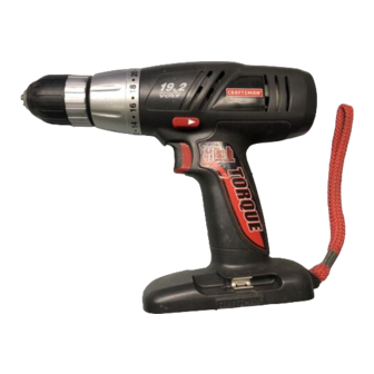
1/2 in., 19.2 volt cordless drill-driver variable speed / reversible
Hide thumbs
Also See for Craftsman 315.114850:
- Operator's manual (19 pages) ,
- Operator's manual (20 pages)
Table of Contents
Advertisement
Quick Links
Operator's Manual
1/2 in., 19.2 VOLT CORDLESS DRILL-DRIVER
Variable Speed / Reversible
Model No.
315.114850
WARNING:
To reduce the risk of
injury, the user must read and understand
the operator's manual before using this
product.
Customer Help Line: 1-800-932-3188
Sears, Roebuck and Co., 3333 Beverly Rd., Hoffman Estates, IL 60179 USA
Visit the Craftsman web page: www.sears.com/craftsman
983000-464
2-04
Save this manual for future reference
Advertisement
Chapters
Table of Contents

Related Manuals for Craftsman Craftsman 315.114850


Summary of Contents for Craftsman Craftsman 315.114850
- Page 1 Customer Help Line: 1-800-932-3188 Sears, Roebuck and Co., 3333 Beverly Rd., Hoffman Estates, IL 60179 USA Visit the Craftsman web page: www.sears.com/craftsman 983000-464 Save this manual for future reference...
-
Page 2: Table Of Contents
If this CRAFTSMAN 1/2 in. Cordless Drill-Driver fails to give complete satisfaction within one year from the date of pur- chase, RETURN IT TO THE NEAREST SEARS STORE OR SEARS SERVICE CENTER IN THE UNITED STATES, and Sears will repair it, free of charge. -
Page 3: General Safety Rules
GENERAL SAFETY RULES WARNING: Remove adjusting keys or wrenches before turning READ AND UNDERSTAND ALL the tool on. A wrench or a key that is left attached to INSTRUCTIONS. Failure to follow all instructions a rotating part of the tool may result in personal injury. listed below, may result in electric shock, fire and/or serious personal injury. -
Page 4: Specific Safety Rules
GENERAL SAFETY RULES SERVICE n When servicing a tool, use only identical replacement parts. Follow instructions in the Maintenance section n Tool service must be performed only by qualified repair of this manual. Use of unauthorized parts or failure to personnel. -
Page 5: Safety Instructions For Charger
SAFETY INSTRUCTIONS FOR CHARGER WARNING! Read and understand all instructions. n Do not let gasoline, oils, petroleum-based products, etc. Failure to follow all instructions listed below, may come in contact with plastic parts. They contain chemicals result in electric shock, fire and/or serious peronal that can damage, weaken, or destroy plastic. -
Page 6: Symbols
SYMBOLS Some of the following symbols may be used on this tool. Please study them and learn their meaning. Proper interpreta- tion of these symbols will allow you to operate the tool better and safer. SYMBOL NAME DESIGNATION/EXPLANATION Volts Voltage Amperes Current Hertz... - Page 7 SYMBOLS The following signal words and meanings are intended to explain the levels of risk associated with this product. SYMBOL SIGNAL MEANING DANGER: Indicates an imminently hazardous situation, which, if not avoided, will result in death or serious injury. WARNING: Indicates a potentially hazardous situation, which, if not avoided, could result in death or serious injury.
-
Page 8: Features
FEATURES SPECIFICATIONS Chuck ................................1/2 in. Keyless Motor ................................... 19.2 Volt DC Switch................................Variable Speed Gear Train ...................................2 Speed No Load Speed ............................0-400/0-1400/min. Clutch .................................. 24 Positions Charger Input ............................120 V. 60 Hz, AC only Charge Rate ................................. 1 Hour Torque.................................. - Page 9 FEATURES TWO-SPEED LEVEL GEAR TRAIN (HI-LO) TORQUE ADJUSTMENT RING KEYLESS CHUCK ® LEVEL REAR VIEW DIRECTION OF ROTATION SELECTOR (FORWARD/REVERSE) SWITCH TRIGGER STORAGE SCREWDRIVER BITS BATTERY PACK BATTERY PACK SHOWN IN CHARGER 4-1/2 IN. WRIST STRAP CHARGER RED LED ON INDICATES FAST CHARGING MODE GREEN LED ON AFTER FAST CHARGING CYCLE, INDICATES FULLY CHARGED BATTERYPACK AND...
-
Page 10: Unpacking
UNPACKING INSTRUCTIONS PACKING LIST When unpacking the tool: 1/2 in. Drill n Carefully remove the tool and accessories from the 1 Hour Charger box. Battery Pack (2) n Make sure that all items listed in the packing list are Double-ended Bit (2) included. -
Page 11: Operation
If green LED continues n If both yellow and green LED come on, this indicates a to remain on, return battery pack to your nearest Sears deeply discharged or defective battery pack. Repair Center for checking or replacing. - Page 12 OPERATION SWITCH TO INSTALL BATTERY PACK See Figure 2. n Lock switch trigger on your drill by placing the direction To turn your drill ON, depress the switch trigger. To turn it of rotation selector in center position. See Figure 5. OFF, release the switch trigger.
- Page 13 OPERATION SWITCH LOCK KEYLESS CHUCK See Figure 5. See Figure 6. The switch trigger can be locked in the OFF position. This Your drill has a keyless chuck. As the name implies, you feature can be used to prevent the possibility of accidental can hand tighten or release drill bits in the chuck jaws.
- Page 14 OPERATION INSTALLING BITS REMOVING BITS See Figure 7. See Figure 7. Lock the switch trigger by placing the direction of Lock the switch trigger by placing the direction of rotation selector in center position. See Figure 5. rotation selector in center position. See Figure 5. Open or close chuck jaws to a point where the open- Loosen the chuck jaws from drill bit.
- Page 15 OPERATION BIT STORAGE LEVEL See Figure 10. When not in use, bits provided with your drill can be placed in the storage area located on the bottom of your ® drill as shown in figure 10. SCREWDRIVER BIT STORAGE AREA Fig.
- Page 16 OPERATION CHUCK REMOVAL n Insert hex key in chuck and tighten chuck jaws se- curely. Tap sharply with a mallet in a counterclockwise See Figures 13, 14, and 15. direction. This will loosen chuck on the spindle. It can n Lock the switch trigger by placing the direction of rota- now be unscrewed by hand.
-
Page 17: Maintenance
All other parts Avoid using solvents when cleaning plastic parts. Most should be replaced at a Sears Service Center. plastics are susceptible to damage from various types of commercial solvents and may be damaged by their use. - Page 18 NOTES...
- Page 19 CRAFTSMAN 1/2 in., 19.2 VOLT CORDLESS DRILL-DRIVER – MODEL NO. 315.114850 The model number will be found on a plate attached to the motor housing. Always mention the model number in all correspondence regarding your 1/2 in., 19.2 VOLT CORDLESS DRILL-DRIVER or when ordering repair parts.
- Page 20 Sears Parts & Repair Center. 1-800-488-1222 Call anytime, day or night (U.S.A. only) www.sears.com To purchase a protection agreement (U.S.A.) or maintenance agreement (Canada) on a product serviced by Sears: 1-800-827-6655 1-800-361-6665 (U.S.A.) (Canada) Para pedir servicio de reparación Au Canada pour service en français:...
- Page 21 Customer Help Line: 1-800-932-3188 Sears, Roebuck and Co., 3333 Beverly Rd., Hoffman Estates, IL 60179 USA Visit the Craftsman web page: www.sears.com/craftsman Save this manual for future reference 983000-522...
- Page 22 If this Craftsman tool fails to give complete satisfaction within one year from date of purchase, RETURN IT TO THE NEAREST SEARS STORE OR SEARS PARTS & REPAIR CENTER IN THE UNITED STATES, and Sears will repair it, free of charge.
-
Page 23: General Safety Rules
GENERAL SAFETY RULES WARNING! n Do not overreach. Keep proper footing and balance READ AND UNDERSTAND ALL IN- at all times. Proper footing and balance enable better STRUCTIONS. Failure to follow all instructions listed control of the tool in unexpected situations. below, may result in electric shock, fire and/or seri- n Use safety equipment. -
Page 24: Specific Safety Rules
GENERAL SAFETY RULES SERVICE n When servicing a tool, use only identical replace- ment parts. Follow instructions in the Maintenance n Tool service must be performed only by qualified section of this manual. Use of unauthorized parts or repair personnel. Service or maintenance performed failure to follow Maintenance Instructions may create a by unqualified personnel may result in a risk of injury. - Page 25 SPECIFIC SAFETY RULES n Do not use dull or damaged blade. Unsharpened or n Do not charge battery tool in a damp or wet loca- tion. Following this rule will reduce the risk of electric improperly set blades produce narrow kerf causing shock.
-
Page 26: Safety Rules For Charger
SAFETY RULES FOR CHARGER WARNING! a. That pins on plug of extension cord are the READ AND UNDERSTAND ALL same number, size and shape as those of INSTRUCTIONS. Failure to follow all instructions plug on charger. listed below, may result in electric shock, fire and/or serious personal injury. -
Page 27: Symbols
SYMBOLS Some of the following symbols may be used on this tool. Please study them and learn their meaning. Proper interpretation of these symbols will allow you to operate the tool better and safer. SYMBOL NAME DESIGNATION/EXPLANATION Volts Voltage Amperes Current Hertz Frequency (cycles per second) - Page 28 SYMBOLS The following signal words and meanings are intended to explain the levels of risk associated with this product. SYMBOL SIGNAL MEANING DANGER: Indicates an imminently hazardous situation, which, if not avoided, will result in death or serious injury. WARNING: Indicates a potentially hazardous situation, which, if not avoided, could result in death or serious injury.
-
Page 29: Features
FEATURES PRODUCT SPECIFICATIONS Motor ................................... 19.2 Volt DC Blade diameter ............................5-1/2 in. (140 mm) Blade Arbor ..............................3/8 in. (9.53 mm) Cutting Depth at 0°..........................1-9/16 in. (39.69 mm) Cutting Depth at 45°..........................1-1/8 in. (28.58 mm) No Load Speed ............................... 4500/min. Charger Input ............................120 V, 60 Hz, AC only Charge Rate .................................. -
Page 30: Assembly
FEATURES SPINDLE LOCK KNOW YOUR LASER TRIM SAW See Figure 1. The spindle lock allows you to secure the blade when turning the blade screw. Before attempting to use this product, familiarize yourself with all operating Features and Safety Rules NOTE: Do not run trim saw with spindle lock engaged. - Page 31 ASSEMBLY INSTALLING BATTERY PACK n Depress spindle lock button and remove blade screw and outer blade washer. See Figure 3. NOTE: Turn blade screw clockwise to remove. NOTE: Battery pack is shipped in a low charge condition. Therefore, it must be charged prior to use. Refer to n Wipe a drop of oil onto inner blade washer and outer page 13, “CHARGING BATTERY PACK”...
- Page 32 ASSEMBLY REMOVING BLADE SPINDLE LOCK See Figure 5. n Remove battery pack from saw. n Remove blade wrench from storage area. n Position saw as shown in figure 5, depress spindle lock button, and remove blade screw. NOTE: Turn blade screw clockwise to remove. SPINDLE LOCK n Remove outer blade washer.
-
Page 33: Operation
Always wear safety goggles or safety under normal circumstances, return both the battery pack glasses with side shields when operating tools. and charger to your nearest Sears Repair Center for Failure to do so could result in objects being thrown electrical check. - Page 34 LED to come on instead of the red LED. After 30 minutes, reinsert the battery pack in the charger. If the green LED continues to remain on, return battery pack to your nearest Sears Repair Center for checking or replacing.
- Page 35 OPERATION KICKBACK See Figures 8 - 11. Kickback occurs when the blade stalls rapidly and the saw is driven back towards you. Blade stalling is caused by any action which pinches the blade in the wood. DANGER: Release switch immediately if blade binds or saw stalls.
- Page 36 OPERATION SAW BLADES STARTING/STOPPING THE SAW See Figure 13. The best of saw blades will not cut efficiently if they are not kept clean, sharp, and properly set. Using a dull blade To start the saw: Depress the switch trigger. will place a heavy load on the saw and increase the dan- Always let the blade reach full speed, then guide the saw ger of kickback.
- Page 37 OPERATION ADJUSTING BLADE DEPTH See Figure 14. Always keep correct blade depth setting. The correct blade depth setting for all cuts should not exceed 1/4 in. (6.35 mm) below the material being cut. More blade depth will increase the chance of kickback and cause the cut to be rough.
- Page 38 OPERATION OPERATING THE SAW See Figures 16 - 18. It is important to understand the correct method for oper- ating the saw. Refer to the figures in this section to learn the correct and incorrect ways for handling the saw. WARNING: To make sawing easier and safer, always maintain proper control of the saw.
- Page 39 OPERATION CROSS CUTTING/RIP CUTTING WORKPIECE See Figure 19. When making a cross cut or rip cut, align the line of cut with the outer blade guide notch on the base as shown in the figure. Since blade thicknesses vary, always make a trial cut in scrap material along a guideline to determine how much, if any, you must offset the guideline to produce an accurate cut.
- Page 40 OPERATION BEVEL CUTTING See Figures 22 - 24. To make the best possible cut, follow these helpful hints: n Align the line of cut with the inner blade guide notch on the base when making 45° bevel cuts. n Make a trial cut in scrap material along a guideline to determine how much you should offset the guideline on the cutting material.
- Page 41 OPERATION POSITIVE 0° BEVEL STOP See Figure 25. ADJUSTMENT The saw has a positive 0° bevel stop that has been factory SCREW adjusted to assure 0° angle of the saw blade when making BEVEL ADJUSTMENT 90° cuts. KNOB TO CHECK POSITIVE 0° BEVEL STOP Follow these directions to check the positive 0°...
-
Page 42: Adjustments
OPERATION POCKET CUTTING n Release the trigger and allow the blade to come to a complete stop. See Figure 26. n Lift the saw from the workpiece. WARNING: Always adjust bevel setting to zero n Clear corners out with a hand saw or sabre saw. before making a pocket cut. -
Page 43: Maintenance
MAINTENANCE REPLACING LASER GUIDE BATTERIES WARNING: When servicing use only identical See Figure 28. Craftsman replacement parts. Use of any other parts n Remove battery pack from saw. may create a hazard or cause product damage. n Make sure laser is turned off. WARNING: Always wear safety goggles or safety n Remove the laser cover by lifting it off its base. -
Page 44: Accessories
Failure to comply with these warnings could result in fire and/or serious injury. ACCESSORIES The following recommended accessories are currently available at Sears retail stores: n 5-1/2 in. Thin Kerf Blade WARNING: Current attachments and accessories available for use with this tool are listed above. Do not use any attachments or accessories not recommended by the manufacturer of this tool. -
Page 47: Variable Speed
Customer Help Line: 1-800-932-3188 Sears, Roebuck and Co., 3333 Beverly Rd., Hoffman Estates, IL 60179 USA Visit the Craftsman web page: www.sears.com/craftsman Save this manual for future reference 983000-193... - Page 48 If this Craftsman tool fails to give complete satisfaction within one year from date of purchase, RETURN IT TO THE NEAREST SEARS STORE OR SEARS PARTS & REPAIR CENTER IN THE UNITED STATES, and Sears will repair it, free of charge.
- Page 49 GENERAL SAFETY RULES WARNING! n Do not overreach. Keep proper footing and balance READ AND UNDERSTAND ALL at all times. Proper footing and balance enable better INSTRUCTIONS. Failure to follow all instructions control of the tool in unexpected situations. listed below, may result in electric shock, fire and/or n Use safety equipment.
- Page 50 GENERAL SAFETY RULES SERVICE n When servicing a tool, use only identical replace- ment parts. Follow instructions in the Maintenance n Tool service must be performed only by qualified section of this manual. Use of unauthorized parts or repair personnel. Service or maintenance performed failure to follow Maintenance Instructions may create a by unqualified personnel may result in a risk of injury.
-
Page 51: Safety Rules For Charger
SAFETY RULES FOR CHARGER WARNING! a. That pins on plug of extension cord are the READ AND UNDERSTAND ALL same number, size and shape as those of INSTRUCTIONS. Failure to follow all instructions plug on charger. listed below, may result in electric shock, fire and/or serious personal injury. -
Page 52: Symbols
SYMBOLS Some of the following symbols may be used on this tool. Please study them and learn their meaning. Proper interpretation of these symbols will allow you to operate the tool better and safer. SYMBOL NAME DESIGNATION/EXPLANATION Volts Voltage Amperes Current Hertz Frequency (cycles per second) - Page 53 SYMBOLS The following signal words and meanings are intended to explain the levels of risk associated with this product. SYMBOL SIGNAL MEANING DANGER: Indicates an imminently hazardous situation, which, if not avoided, will result in death or serious injury. WARNING: Indicates a potentially hazardous situation, which, if not avoided, could result in death or serious injury.
-
Page 54: Features
FEATURES PRODUCT SPECIFICATIONS Motor .................................19.2 Volts DC Switch................................Variable Speed No Load Speed ..............................0-3100/min. Charger Input ............................120 V, 60 Hz, AC only Charge Rate ..................................1 hour Stroke Length ................................7/8 in. BASE (SHOE) ASSEMBLY LOCK-OFF BUTTON SWITCH TRIGGER SAW BLADE BLADE CLAMP LOCK / RELEASE LEVER... - Page 55 FEATURES KNOW YOUR RECIPROCATING SAW SWITCH To turn your saw ON, depress the lock-off button and pull See Figure 1. switch trigger. Release switch trigger to turn your saw Before attempting to use this product, familiarize yourself OFF. with all operating Features and Safety Rules. VARIABLE SPEED TOOLLESS BLADE CLAMP This tool has a variable speed switch that delivers higher...
-
Page 56: Assembly
ASSEMBLY UNPACKING WARNING: If any parts are missing do not operate this tool until the missing parts are replaced. Failure This product has been shipped completely assembled. to do so could result in possible serious personal n Carefully remove the tool and any accessories from the injury. - Page 57 If the green LED continues n Red LED should remain on for approximately 1 hour to remain on, return battery pack to your nearest Sears then the green LED will come on. Green LED on Repair Center for checking or replacing.
- Page 58 OPERATION TO REMOVE / ATTACH BATTERY PACK TO INSTALL SAW BLADE See Figure 4. See Figure 3. Remove battery pack. TO REMOVE: Locate latches on side of battery pack and depress WARNING: Failure to remove battery pack from both sides to release battery pack from your saw. saw could result in accidental starting causing Remove battery pack from your saw.
- Page 59 OPERATION BASE (SHOE) ASSEMBLY GENERAL CUTTING See Figure 5. See Figure 6. The base assembly of your reciprocating saw pivots up Hold your saw firmly in front of and clearly away from you. and down in both directions. It also is adjustable, allowing Make sure saw blade is clear of any foreign material.
- Page 60 OPERATION PLUNGE CUTTING METAL CUTTING See Figure 7. See Figure 8. Mark the line of cut clearly. Choose a convenient starting Metals such as sheet steel, pipe, steel rods, aluminum, point inside the area to be cut out and place the tip of brass, and copper may be cut with your saw.
-
Page 61: Maintenance
If the operation is dusty, also wear a repaired or replaced by the customer. All other parts dust mask. should be replaced at a Sears Service Center. WARNING: To avoid serious personal injury, always remove the battery pack from the tool when cleaning or performing any maintenance. -
Page 62: Accessories
ACCESSORIES The following recommended accessories are currently available at Sears retail stores: BLADE TYPES LENGTH TEETH PER IN. For fast smooth cuts in woods, masonite, plastics, hard composition board and all plunge cutting. Keyhole blade shape permits cutting in hard to reach areas........6 ....6 For fast, smooth, deep cuts through thick wood, plastic, composition board, and hardboard... -
Page 63: Parts List
CRAFTSMAN 19.2 VOLT RECIPROCATING SAW – MODEL NO. 315.114270 The model number will be found on a plate attached to the motor housing. Always mention the model number in all correspondence regarding your 19.2 VOLT RECIPROCATING SAW or when ordering repair parts. SEE BACK PAGE FOR PARTS ORDERING INSTRUCTIONS PARTS LIST Part... - Page 64 Sears Parts & Repair Center. 1-800-488-1222 Call anytime, day or night (U.S.A. only) www.sears.com To purchase a protection agreement (U.S.A.) or maintenance agreement (Canada) on a product serviced by Sears: 1-800-827-6655 1-800-361-6665 (U.S.A.) (Canada) Para pedir servicio de reparación Au Canada pour service en français:...
- Page 65 CAUTION: Read and follow all Safety Rules and Operating Instructions before first use of this product. Customer Help Line: 1-800-932-3188 Sears, Roebuck and Co., 3333 Beverly Rd., Hoffman Estates, IL 60179 USA Visit the Craftsman web page: www.sears.com 983000-199 2-03...
-
Page 66: Warranty
If this Fluorescent Light fails to give complete satisfaction within one year from the date of purchase, RETURN IT TO THE NEAREST SEARS STORE IN THE UNITED STATES, and Sears will repair it, free of charge. If this Fluorescent Light is used for commercial or rental purposes, this warranty applies for only 90 days from the date of purchase. -
Page 67: General Safety Rules
GENERAL SAFETY RULES ■ Do not overreach. Keep proper footing and bal- WARNING: Read and understand all instructions. ance at all times. Proper footing and balance enable Failure to follow all instructions listed below, can better control of the tool in unexpected situations. Do result in electric shock, fire and/or serious personal not use on a ladder or unstable support. - Page 68 SPECIFIC SAFETY RULES Hold tool by insulated gripping surfaces when performing an operation where the cutting tool may contact hidden wiring. Contact with a "live" wire will make exposed metal parts of the tool "live" and shock the operator. ■ Under extreme usage or temperature conditions, ADDITIONAL RULES FOR SAFE OPERATION battery leakage may occur.
-
Page 69: Specific Safety Rules
SPECIFIC SAFETY RULES IMPORTANT SAFETY INSTRUCTIONS FOR a. That pins on plug of extension cord are the CHARGER same number, size and shape as those of plug on charger. ■ Save these instructions. This manual contains b. That extension cord is properly wired and in important safety and operating instructions for good electrical condition;... -
Page 70: Symbols
SYMBOLS Important: Some of the following symbols may be used on your tool. Please study them and learn their meaning. Proper interpretation of these symbols will allow you to operate the tool better and safer. SYMBOL NAME DESIGNATION/EXPLANATION Volts Voltage Amperes Current Hertz... -
Page 71: Operation
If green LED continues to remain ■ Normally, the red LED on charger will come on. This on, return battery pack to your nearest Sears Repair indicates charger is in fast charging mode. Center for checking or replacing. - Page 72 LED comes on. Return battery pack and charger to SWITCH your nearest Sears Service Center for checking or See Figure 3. replacing. Also, if you are removing battery pack from To turn light on and off, depress switch trigger.
-
Page 73: Maintenance
MAINTENANCE Do not abuse power tools. Abusive practices can damage WARNING: When servicing, use only identical tool as well as workpiece. Craftsman replacement parts. Use of any other part may create a hazard or cause product damage. WARNING: Do not attempt to modify this worklight or create accessories not recommended for use with WARNING: Do not at any time let brake fluids,... - Page 74 MAINTENANCE BATTERIES To preserve natural resources, please recycle or dispose of batteries properly. The battery pack for this light is equipped with nickel- This product contains nickel-cadmium cadmium rechargeable batteries. Length of service from batteries. Local, state or federal laws each charging will depend how much the light is used.
- Page 75 NOTES...
- Page 76 Sears Parts & Repair Center. 1-800-488-1222 Call anytime, day or night (U.S.A. only) www.sears.com To purchase a protection agreement (U.S.A.) or maintenance agreement (Canada) on a product serviced by Sears: 1-800-827-6655 1-800-361-6665 (U.S.A.) (Canada) Para pedir servicio de reparación Au Canada pour service en français:...