Table of Contents
Advertisement
Advertisement
Table of Contents

Related Manuals for Garmin GPS 75


Summary of Contents for Garmin GPS 75
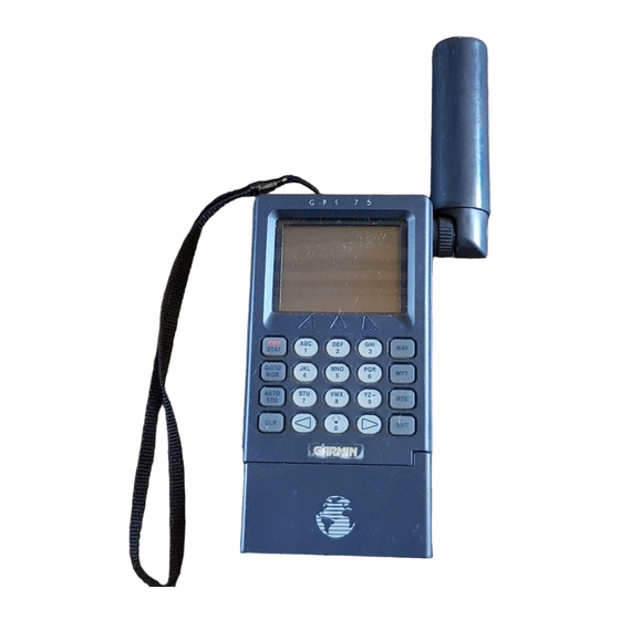
- Page 2 GPS 75 Personal Navigator OWNER'S MANUAL (Software Version 2.20 or above)
- Page 3 GARMIN. Information in this document is subject to change without notice. GARMIN reserves the right to change or improve their products and to make changes in the content without obligation to notify any person or organization of such changes or improvements.
- Page 4 This manual and accompanying quick reference guide provide complete information on safely operating the GPS 75 to its full potential. practice voyage has been planned for you to practice your navigation skills using the built-in simulator. Afterwards, try a trip of your own to...
- Page 5 Owner's Manual and thoroughly practice operation using the simulator mode prior to actual use. When in actual use, carefully compare indications from the GPS 75 to all available navigation sources including the information from other NAVAIDs, visual sightings, charts, etc.
-
Page 6: Table Of Contents
TABLE OF CONTENTS CHAPTER INTRODUCING THE GARMIN GPS 75 1.1 Capabilities 1.2 Operations GETTING STARTED 2.1 Front Panel 2.2 Softkey Operation 2.3 Cursor and Fields 2.4 Keypad Operation 2.5 Entering Data 2.6 Viewing Messages 2.7 Operating Modes BASIC OPERATION 3.1 Power On 3.2 Satellite Status Pages... - Page 7 ADVANCED WAYPOINT FEATURES 5.1 Nearest Waypoints 5.2 Proximity Waypoints 5.3 Reference Waypoints 5.4 Waypoint Scanning AUXILIARY FUNCTIONS 6.1 Operating Mode and Filters 6.2 Plotting Setup 6.3 Units/Heading Setup 6.4 Alarms and CDI Setup 6.5 Date/Time 6.6 Audio and Display Setup 6.7 Interface Setup 6.8 Map Datum Selection 6.9 Beacon Receiver Setup...
-
Page 10: Operations
SOFTKEY OPERATION Information displayed on the LCD is commonly referred to as a “page.” The GPS 75 works with softkey operation. At the bottom of the screen is a list of page options. To select a different page, press the appropriate softkey below the desired menu option. -
Page 11: Cursor And Fields
CURSOR AND FIELDS Confirmation Field Cyclic Field The area of the page which is highlighted in reverse video is called the cursor. The cursor may be moved to locations on the page called fields which allow you to enter data or change options. You will encounter five types of fields. - Page 12 Pressing GOTO/MOB once allows you to initiate the GOTO function, setting an instantaneous course to any waypoint (see Section 3.7). Pressing GOTO/MOB twice allows you to initiate the Man Overboard function, setting an immediate course to the captured position (see Section 3.9). Pressing AUTOSTORE allows you to capture your present position instantaneously (see Section 3.6).
-
Page 13: Entering Data
(see Section 6.6). VIEWING MESSAGES From time to time, the GPS 75 will use a message to tell you of conditions needing attention. annunciator will flash. When this occurs, press PWR/STAT to view the new message(s). -
Page 14: Operating Modes
YOU SHOULD NEVER ATTEMPT TO USE THE SIMULATOR MODE FOR ACTUAL NAVIGATION. If you are using your GPS 75 for the first time, you are encouraged to review Chapter 3 which introduces the GPS 75's basic features, and Chapter 6 on custom setups. Afterward, you may want to read through the rest of this manual and make further use of the built-in simulator to practice with the advanced features. -
Page 15: Basic Operation
CHAPTER 3 BASIC OPERATION 3.1 POWER ON After you turn your GPS 75 on, it will conduct a series of self tests and display the following notice: Following completion of the tests, the Satellite Bar Graph Page (see Section 3.2) will be displayed, and the GPS 75 will begin acquiring satellites. -
Page 16: Satellite Status
3.2 SATELLITE STATUS PAGES There are four status pages available by pressing PWR/STAT. pages display satellite tracking status, and the fourth is a menu of auxiliary functions (messages, setups, and utilities). The softkeys at the bottom of each page allow selecting pages: (status), SKY (skyview), and AUX (auxiliary menu). -
Page 17: Present Position
(see Section 6.8), as well as a choice of altitude above mean sea level (MSL) or time (cyclic field). (Note: information will not be displayed when the GPS 75 is acquiring satellites.) Skyview The azimuth useful This page speed,... - Page 18 When the GPS 75 is performing 2D navigation, the last known altitude will be used in the latitude/longitude computation. If the altitude is not accurate within a few hundred feet, you should manually enter your altitude. To enter the altitude (2D only)...
-
Page 19: Waypoints
3.4 WAYPOINTS The GPS 75 allows you to create, store, and use 250 alphanumeric waypoints. A waypoint consists of a name (up to six letters and/or numbers), its latitude/longitude location, last time/date of modification, and a one-line comment. There are four waypoint pages. The softkeys... -
Page 20: Waypoint List
3.5WAYPOINT LIST The Waypoint List Page allows viewing of the stored waypoints in the unit. The list may be scrolled, with the arrow keys, to view all the waypoints. From this page, waypoints may be selected for deletion, renaming, or to activate a direct GOTO. (See Section 3.7.) NOTE: If you attempt to delete a proximity or route waypoint, a message will be displayed. -
Page 21: Getting There Fast--Goto
The AutoStore Page displays the waypoint name, captured position, and optional storage route. assigned as a three digit number. You may change this to any name you desire. Autostore and will be part of the 250 available waypoints. To capture present position... ·... -
Page 22: Navigating To A Waypoint
To activate the GOTO function... · Press GOTO. The above page will be displayed with the cursor on the GOTO waypoint field. If the GPS 75 is currently navigating to a waypoint, that waypoint will be offered as the default GOTO waypoint. - Page 23 Navigation Summary The Navigation Summary Page displays direction, distance and speed information to direct you along a route or a GOTO destination. active leg (route) waypoints or GOTO waypoint is shown at the top of the screen. The CDI is at the bottom of the page. Current CDI scale setting is shown at each end of the scale.
- Page 24 track. The outer lines give a perspective view of the distance to a waypoint. As the waypoint comes into range, it will be displayed and the outer lines will become parallel. · Press POSN softkey . waypoint name by scrolling to the point with the arrow keys. A GOTO may be performed by pressing GOTO while the cursor is on the waypoint.
-
Page 25: Man Overboard
GARMIN, located at GARMIN's Lenexa, Kansas facility, is also provided. Just for fun, let's go to GARMIN! Turn on your GPS 75. The power on notices will be displayed followed by the Satellite Bar Graph. The GPS 75 is ready to accept your commands. - Page 26 Plus POSN Softkey if needed 3-12 Select the simulator mode... · Press PWR/STAT to select a Status Page. · If the Auxiliary Page is not displayed, press underneath the AUX banner to select it. · Use the right arrow key to highlight “Op Mode”, press ENT.
- Page 27 “GARMIN” waypoint. · If the “GARMIN” waypoint is not listed, you must add it to the GPS 75's memory before you can activate the GOTO function. Press the WPT softkey.
- Page 28 (e.g., to get the letter “G”, press the “3” key and then the left arrow). · Enter the coordinates for the “GARMIN” waypoint using the same method described for setting the present position (see Section 3.3). Note, however, that depending on the unit setups, Lat/Lon coordinates will be entered in one (degrees only), two (degrees/ minutes) or three (degrees/minutes/seconds) fields.
- Page 29 WPT and then the LIST softkey, if needed. · With the right arrow key, move cursor waypoint. · Press GOTO/MOB. The waypoint “GARMIN” carried over to the GOTO Page. (You can “import” waypoints to the GOTO Page from several other pages, including...
-
Page 30: Capabilities
Examine the Navigation Information... At this point, you can explore the capabilities of the GPS 75. While you are on the Navigation Summary Page, you may want to examine other information not currently displayed (see Section 3.8). · As the unit is navigating, you will notice the Range (RNG) to GARMIN decreasing. - Page 31 CLR until the estimated time enroute (ETE) is displayed. · Highlight the ground track (TRK) field (bottom left) and press CLR until groundspeed (GS) is displayed. · Highlight the bearing (BRG) field (top left) and press CLR until ground track (TRK) is displayed. You now have an entirely different Navigation Summary Page that should look something like this: Let's Look at a Different Navigation Page...
- Page 32 3-18 Next Stop, Position Page... · Select the Present Position Page with the POSN softkey. Note that ground track (TRK) and ground speed (GS) are shown on the top line, followed by the current latitude and longitude on the next two lines.
- Page 33 Experiment with your GPS 75. You are on your way to mastering the GPS 75. If you let the simulator run, you will eventually get a message, “Approaching GARMIN”, just prior to reaching the waypoint. Press PWR/STAT to view the message;...
-
Page 35: Creating And Copying A Route
There are 3 route pages in the GPS 75. The softkeys at the bottom of each page allow cycling through each page: (active route), and LIST (route list). 4.2CREATING AND COPYING A ROUTE The Route Definition page allows you to create, change, review, copy, and activate routes. -
Page 36: Activating Routes
· A third field now appears in the top right corner. field and select the destination route number with CLR. · Press ENT. The route is now copied. 4.3ACTIVATING ROUTES Routes are activated on the Route Definition Page also. activate any route in the displayed order, or in reverse order. Remember, when a new route is activated, the previous contents of route 0 will be overwritten. -
Page 37: Editing Routes
4.4EDITING ROUTES · If you attempt to add a waypoint to a route that already contains 20 waypoints, you will be informed with the message, “Route is Full”. NOTE: You may also edit a route from the Active Route Page (see Section 4.6). -
Page 38: Active Route
4.6ACTIVE ROUTE Active Leg Waypoint List The Active Route Page displays the waypoints of the active route starting with the “active from” and “active to” waypoints on the top line. Press the ACTV softkey to select this page. The Waypoint List displays route waypoints starting with the “active to” waypoint. - Page 39 · Press ENT to delete the route. Building Routes with AutoStore... The GPS 75's AutoStore a route as you go. With autostore, each time you turn on a new track, pass a significant landmark, or reach some location of interest, you can save the location and create a route at the same time.
-
Page 40: Advanced Waypoint Features
ADVANCED WAYPOINT FEATURES 5.1NEAREST WAYPOINTS An important feature of the GPS 75 is the ability to display up to nine nearest waypoints, within 100 nautical miles of your present position. In an emergency, you may use the nearest waypoint feature to find the closest point of safety in your area. -
Page 41: Reference Waypoints
Another way to create a waypoint is by referencing an existing waypoint. from a reference waypoint, the GPS 75 is able to compute a latitude and longitude location for the new waypoint. · Highlight the “>Ref:” field and enter the existing waypoint that will be used as reference. -
Page 42: Waypoint Scanning
· Enter the bearing and distance from the existing waypoint to the new waypoint. · Press ENT. A latitude and longitude location for the new waypoint should now be displayed. 5.4WAYPOINT SCANNING Throughout this manual, each time we have encountered a waypoint name field, we have entered the waypoint name with the alphanumeric keys. -
Page 43: Auxiliary Functions
AUXILIARY FUNCTIONS The GPS 75's auxiliary pages allow you to do utility and setup functions to customize your unit. The 11 auxiliary pages are accessible from the auxiliary menu (see Section 3.2) by highlighting the page you want and pressing ENT. The softkeys allow changing to previous (PREV) and next (NEXT) pages. -
Page 44: Route (
6.2PLOTTING SETUP route (DTK Up). To select the desired option, highlight this field and press CLR. Your present position and nearby waypoints are displayed on the plot map at all times. additional information will be displayed on the plot map. display the active route and a stored ground track showing where you have been, only the active route, only the ground track, or neither. -
Page 45: Units/Heading Setup
If the planned course will be primarily straight line travel, you should select “Resolution” storage. In this application, considerably less memory is used for the same distance traveled. To store the Ground Track by Resolution... · Highlight the storage frequency field and select “Resolution” with CLR. -
Page 46: Alarms And Cdi Setup
(.01 unit) may result in a false alarm. Please note that under certain circumstances (below average satellite geometry, degraded reception, etc.) the position error of the GPS 75 may be greater than the lowest scale settings available for this alarm. -
Page 47: Date/Time
“D-Bar”. 6.5DATE/TIME The cyclic field for “Display” options determines which time, UTC or Local, will be displayed on other GPS 75 pages. To change this option, highlight this field and press CLR. The Date/Time Page displays the... -
Page 48: Audio And Display Setup
From the Interface Page, you may select the input or output format needed to connect your GPS 75 to other equipment: another GPS 75, a PC, etc. You may select input/output NONE), NMEA output, GARMIN input/output, or RTCM input by highlighting the cyclic field and pressing CLR. -
Page 49: Map Datum Selection
(capable of output in 6 of 8 byte format as specified by RTCM SC-104, version 2.0) by connecting the device to the input port on the back of the GPS 75 and selecting an RTCM input interface mode. Two RTCM input modes are available, one which allows no output and another which allows NMEA output in 0180, 0182, or 0183 format. -
Page 50: Beacon Receiver Setup
Incorrect entries for a user-defined datum may result in substantial position errors. 6.9BEACON RECEIVER SETUP mode is not selected, the GPS 75 will only display the message “No RTCM/NMEA 0183 interface selected” on the Beacon Receiver Setup Page. Once the correct interface is chosen, the Beacon Receiver Setup Page will display as shown above. -
Page 51: Sunrise/Sunset Planning
frequency and bit rate which you selected (or the default frequency of 304.0 kHz and bit rate of 100 bps if no previous beacon has been tuned). You may enter you own frequency (between 283.5 kHz and 325.0 kHz in 0.5 kHz increments) and bit rate if you desire. -
Page 52: Trip & Fuel Planning
(a given leg or all of the route) to calculate for. The final step is to enter speed and fuel flow rates. The GPS 75 will then calculate the desired track (DTK), fuel requirements (REQ), range (RNG), and estimated time enroute (ETE). - Page 53 · The fuel flow (Flow) field is highlighted. Enter the estimated fuel flow followed by ENT. · The GPS 75 will now display the calculated figures. To perform a Trip and Fuel Plan for a route... · Highlight the “Leg>” field and select the desired leg, or select “All”...
-
Page 54: Messages
No RTCM Input - A beacon receiver is improperly connected to the input port on the back of the GPS 75, a connected beacon receiver is not transmitting in an RTCM SC-104 version 2.0 format, or the baud rates do not match between the GPS 75 and the beacon receiver. - Page 55 The GPS 75 will not allow more than 20 waypoints per route. Route Not Empty - An attempt has been made to copy a route to a non- empty route. The GPS 75 will not allow you to copy a route to a non- empty route.
- Page 56 RTCM Input Failed - RTCM data was being received but the connection has been lost. Searching the Sky - The GPS 75 is in the search-the-sky mode. Allow the unit to complete its data collection before turning it off. This process takes approximately 15 minutes.
-
Page 57: Glossary And Navigation Terms
APPENDIX B GLOSSARY AND NAVIGATION TERMS DEFINITIONS This section provides an illustration of and definitions for the terms used in this manual. - Page 58 Velocity/time terms: Ground speed. position; also known as velocity over ground (VOG). VMG Velocity made good. desired course. It is the speed at which you are closing on the “active to” waypoint. Estimated time of arrival. reach the “active to” waypoint based on VMG. selectable as either UTC or local.
-
Page 59: Course To Steer (Cts
B.2 COURSE TO STEER (CTS) Course To Steer is a GARMIN exclusive that recommends an optimal direction to steer that will guide you to the course and proceed efficiently along your route. - Page 60 As an example, suppose you activate the route illustrated above. The GPS 75 chooses the closest leg with a desired track of 45 degrees but your position happens to be two nautical miles off course. The unit will automatically compute the optimal course to steer (which is due north in this example).
-
Page 61: Installation And Maintenance
Humidity: PERFORMANCE Receiver: Acquisition Time: 2 minutes 2D (typical) Accuracy: APPENDIX C GPS 75 SPECIFICATIONS Waterproof Portable: 3.23"w x 6.26"h x 1.46"d (82mm x 159mm x 37mm) Fixed: 3.23"w x 4.87"h x 1.46"d (82mm x 124mm x 37mm) 14 ounces (0.4 kg) without battery pack 19 ounces (0.54 kg) with battery pack... - Page 62 Dynamics: INTERFACES NMEA 0180 NMEA 0182 NMEA 0183 (Version 1.5; December 1987) Approved sentences: GPBWC, GPGLL, GPRMB, GPRMC, GPR00, GPWPL, GPXTE Proprietary sentences: PGRMZ PGRMM Transmission rate: GPBWC, GPVTG, GPGLL, GPRMB, GPRMC, GPXTE, and PGRMZ transmitted once every two seconds. GPR00 transmitted once every (# of all waypoints + 1) * 2 seconds.
-
Page 63: Electrical Wiring
ELECTRICAL WIRING The GPS 75 power/data cable allows you to connect the unit to vehicle power systems, other marine electronics, a remote alarm/beeper, or an external DGPS device that outputs RTCM SC-104, version 2.0 data. The harness will plug into the connector located on the rear panel of the GPS To connect to vehicle power systems... - Page 64 The GPS 75 will drive a remote alarm or relay that requires no more than 100 milliamps of current. (WARNING: Devices which draw current in excess of 100 milliamperes may damage your unit and will void your warranty. Consult the instructions included with the remote alarm or relay for current drain information.)
-
Page 65: Universal Mount Installation
UNIVERSAL MOUNT INSTALLATION The GPS 75 is equipped with a universal mount for fixed installations. The universal mount may be installed above the dash or attached to a surface as shown below. Although your GPS 75 is designed to withstand the marine environment, it is recommended that it be mounted in a location which provides protection from sun and spray. - Page 66 To install universal mount above dash... The universal mount is completely assembled and ready for fixed installation above dash. appropriate screws (#8 flat head screws are recommended). To install universal mount on a surface... · Mount the base to the boat dash using...
- Page 67 Remove the E-ring from the special screw under the base using a pair of pliers. · Remove the lever. A spring and detent pin are contained within a recess on this lever. · Unscrew the special screw and remove it from the base. ·...
-
Page 68: Universal Mount Operation
UNIVERSAL MOUNT OPERATION The universal mount has been designed for easy insertion and removal of your GPS 75 if you wish to use the unit in another boat or vehicle, plan at home, or prevent theft. To insert the GPS 75 into the universal mount... - Page 69 · Disconnect the antenna or antenna cable. · Apply enough force to the release tab to allow the unit to pass as shown above. · Pull the bottom of the GPS 75 out, then rotate the top downward and out. To adjust the universal mount angle...
-
Page 70: Battery Pack Operation
BATTERY PACK OPERATION The GPS 75 is supplied with a sealed, 4-cell alkaline battery pack. The battery pack must be removed from the unit in order to replace the cells. To remove the battery pack... · Push down on the spring tab on the right side of the battery pack. -
Page 71: Maintenance
· Slide the sleeve over the cage until it snaps into place, taking care that you do not tear the gaskets which seal the battery pack. MAINTENANCE The GPS 75 is constructed of high quality material and should not require user maintenance. GARMIN service center. -
Page 72: Product Support
The internal memory battery should typically last three to five years. If the GPS 75 detects a low memory battery, you will be informed with the message “Memory Battery Low”. You should return your unit to an authorized GARMIN service center as soon as possible for service. -
Page 73: Map Datums
The following is a list of the GPS 75 map datum selections and the corresponding map datum name (including the area of application): Adindan Afgooye AIN EL ABD 1970 Anna 1 Astro 1965 ARC 1950 ARC 1960 Ascension Island ‘58 Astro B4 Sorol Atoll Astro Beacon “E”... - Page 74 Geodetic Datum ‘49 Guam 1963 Gux 1 Astro Hjorsey 1955 Hong Kong 1963 Indian Bangladesh Indian Thailand Ireland 1965 ISTS 073 ASTRO ‘69 Johnston Island Kandawala Kergulen Island Kertau 1948 L.C. 5 Astro Liberia 1964 Luzon Mindanao Luzon Philippines Mahe 1971 Marco Astro M a s s awa Merchich...
- Page 75 Nahrwn Masirah Ilnd Nahrwn Saudi Arbia Nahrwn United Arab Naparima BWI Observatorio 1966 Old Egyptian Old Hawaiian O m a n Ord Srvy Grt Britn Pico De Las Nieves Pitcairn Astro 1967 Prov So Amricn ‘56 Prov So Chilean ‘63 Puerto Rico Qatar National Qornoq...
- Page 76 UTC TIME TO LOCAL TIME OFFSET Reference the chart below to find the UTC-to-local time offset for your longitude zone. (If you are in a daylight savings time zone, add one hour to the offset.) For example, if you are at longitude W081°00.00' and UTC time is 16:00, local time is 11:00 standard time.
- Page 77 Active from waypoint Active route Active Route Page Active to waypoint Alarm Clock Alarm/CDI Page Alarms alarm clock anchor drag arrival proximity Along Track Distance (ATD) B-3 Alphanumeric field Altitude G P S manual entry u n i t s Anchor drag alarm Arrival alarm Audio/Display Setup Page...
- Page 78 Field alphanumeric b a r confirmation cyclic numeric Filters position velocity Fuel Planning GOTO waypoint Ground Speed (GS) Heading Selection (HDG) Installation Interface format Interface Page Interval, track storing Keypad using tone Local date/time Magnetic variation automatic true north user-defined Maintenance Man overboard (MOB) F - 2...
- Page 79 Proximity alarm Proximity Waypoint Page Range (RNG) Relative Bearing Pointer Resolution, track storing Route Definition Page Route List Page Routes activating building with AutoStore clearing copying creating deleting editing active routes editing storage routes navigating Satellite Status bar graph table Satellite Status Page Scale, Plot Page Searching the sky...