Table of Contents
Advertisement
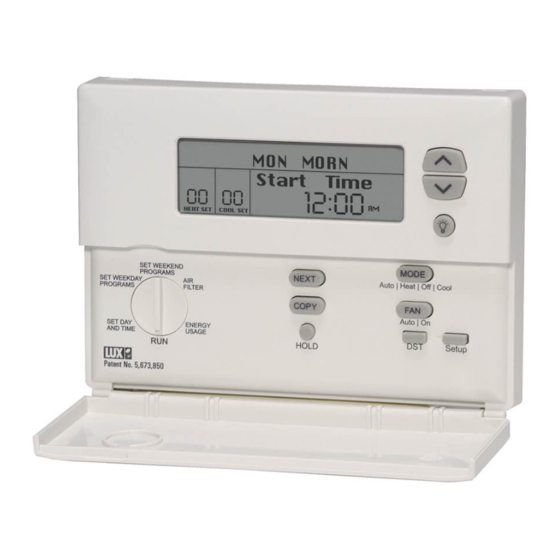
LUXPRO EVERYTHING 'STAT
INSTALLATION AND OPERATING INSTRUCTIONS
1.
FEATURES . . . . . . . . . . . . . . . . . . . . . . . . . . . . . . . . . . . . . . . . . . . . . 2
2.
COMPATIBILITY . . . . . . . . . . . . . . . . . . . . . . . . . . . . . . . . . . . . . . . . 2
2.1. HEAT STAGES . . . . . . . . . . . . . . . . . . . . . . . . . . . . . . . . . . . . . . . . . . . . 2
2.2. COOLING/COMPRESSOR STAGES . . . . . . . . . . . . . . . . . . . . . . . . . . 2
2.3. ELECTRICAL RATINGS . . . . . . . . . . . . . . . . . . . . . . . . . . . . . . . . . . . . 2
3.
INSTALLATION . . . . . . . . . . . . . . . . . . . . . . . . . . . . . . . . . . . . . . . . . 2
3.1. TOOLS REQUIRED . . . . . . . . . . . . . . . . . . . . . . . . . . . . . . . . . . . . . . . . 2
3.2. LOCATION . . . . . . . . . . . . . . . . . . . . . . . . . . . . . . . . . . . . . . . . . . . . . . . 3
3.3. REMOVAL OF OLD UNIT. . . . . . . . . . . . . . . . . . . . . . . . . . . . . . . . . . . 3
3.4. MOUNTING . . . . . . . . . . . . . . . . . . . . . . . . . . . . . . . . . . . . . . . . . . . . . . 3
3.5. WIRING . . . . . . . . . . . . . . . . . . . . . . . . . . . . . . . . . . . . . . . . . . . . . . . . . 3
3.5.1 TERMINAL DEFINITIONS . . . . . . . . . . . . . . . . . . . . . . . . . . . . . . . . . . . . 3
3.5.2 FREEZE PROTECTION. . . . . . . . . . . . . . . . . . . . . . . . . . . . . . . . . . . . . . . 4
3.5.3 SPECIAL WIRING NOTES. . . . . . . . . . . . . . . . . . . . . . . . . . . . . . . . . . . . 4
3.5.4 COMMON WIRING OPTIONS . . . . . . . . . . . . . . . . . . . . . . . . . . . . . . . . . 4
3.5.7 SINGLE STAGE FURNACE HEATING AND SINGLE STAGE
COOLING SYSTEM LABEL CROSS REFERENCE . . . . . . . . . . . . . . . . . . 4
3.5.8 TWO STAGE HEAT, SINGLE STAGE COOL HEAT PUMP SYSTEM
LABEL CROSS REFERENCE . . . . . . . . . . . . . . . . . . . . . . . . . . . . . . . . . . 5
3.5.9 WIRING DIAGRAMS. . . . . . . . . . . . . . . . . . . . . . . . . . . . . . . . . . . . . . . . 5
3.6. INSTALL BATTERIES . . . . . . . . . . . . . . . . . . . . . . . . . . . . . . . . . . . . . . 9
3.7. INSTALLER SETUP. . . . . . . . . . . . . . . . . . . . . . . . . . . . . . . . . . . . . . . . 9
3.7.1 ACCESS AND NAVIGATE INSTALLER SETUP MENU. . . . . . . . . . . . . . . 9
FURNACE SYSTEM TYPE SELECTED: . . . . . . . . . . . . . . . . . . . . . . . . . . 10
PUMP SYSTEM TYPE SELECTED. . . . . . . . . . . . . . . . . . . . . . . . . . . . . . 10
3.7.4 COMPLETING YOUR INSTALLATION . . . . . . . . . . . . . . . . . . . . . . . . . . . 11
4.
OPERATION . . . . . . . . . . . . . . . . . . . . . . . . . . . . . . . . . . . . . . . . . . . . 11
4.1. OPERATING BASICS . . . . . . . . . . . . . . . . . . . . . . . . . . . . . . . . . . . . . . 11
4.1.1 UP/DOWN ARROW CHANGE KEYS . . . . . . . . . . . . . . . . . . . . . . . . . . . . 11
4.1.2 SET DAY AND TIME . . . . . . . . . . . . . . . . . . . . . . . . . . . . . . . . . . . . . . . . 11
4.1.3 DEFAULT PROGRAM . . . . . . . . . . . . . . . . . . . . . . . . . . . . . . . . . . . . . . . 11
WARNING: Use Energizer
Mt. Laurel, New Jersey 08054, USA
Energizer
®
is a registered trademark of Eveready Battery Company, Inc.
DURACELL
®
is a registered trademark of The Gillette Company, Inc.
4.1.4 MODES . . . . . . . . . . . . . . . . . . . . . . . . . . . . . . . . . . . . . . . . . . . . . . . . . . 11
4.1.5 DISPLAY ILLUMINATION . . . . . . . . . . . . . . . . . . . . . . . . . . . . . . . . . . . . 12
4.2. USER SETUP MENU . . . . . . . . . . . . . . . . . . . . . . . . . . . . . . . . . . . . . . 12
4.2.1 ACCESS AND NAVIGATE USER SETUP MENU. . . . . . . . . . . . . . . . . . . . 12
4.2.2 KEYBOARD LOCK . . . . . . . . . . . . . . . . . . . . . . . . . . . . . . . . . . . . . . . . . . 12
4.2.3 BEEP . . . . . . . . . . . . . . . . . . . . . . . . . . . . . . . . . . . . . . . . . . . . . . . . . . . . 12
4.2.4 TEMPERATURE DISPLAY FORMAT (F/C DISPLAY) . . . . . . . . . . . . . . . . 13
4.2.5 CLOCK FORMAT . . . . . . . . . . . . . . . . . . . . . . . . . . . . . . . . . . . . . . . . . . . 13
4.2.6 CALIBRATION OFFSET . . . . . . . . . . . . . . . . . . . . . . . . . . . . . . . . . . . . . . 13
4.2.7 MAXIMUM HEAT SETTING. . . . . . . . . . . . . . . . . . . . . . . . . . . . . . . . . . . 13
4.2.8 MINIMUM COOL SETTING. . . . . . . . . . . . . . . . . . . . . . . . . . . . . . . . . . . 13
4.2.9 SMART RECOVERY . . . . . . . . . . . . . . . . . . . . . . . . . . . . . . . . . . . . . . . . 13
4.2.10 FILTER LIMIT . . . . . . . . . . . . . . . . . . . . . . . . . . . . . . . . . . . . . . . . . . . . . 13
4.2.11 USER SETUP MENU: . . . . . . . . . . . . . . . . . . . . . . . . . . . . . . . . . . . . . . . 13
4.3. ADVANCED FEATURES AND OPERATION . . . . . . . . . . . . . . . . . . . . 13
4.3.1 EMERGENCY HEAT. . . . . . . . . . . . . . . . . . . . . . . . . . . . . . . . . . . . . . . . . 13
4.3.2 FAN MODES . . . . . . . . . . . . . . . . . . . . . . . . . . . . . . . . . . . . . . . . . . . . . . 13
4.3.3 VACATION HOLD. . . . . . . . . . . . . . . . . . . . . . . . . . . . . . . . . . . . . . . . . . . 14
4.3.4 DAYLIGHT SAVINGS TIME ADJUSTMENT (DST) . . . . . . . . . . . . . . . . . 14
4.3.5 AIR FILTER . . . . . . . . . . . . . . . . . . . . . . . . . . . . . . . . . . . . . . . . . . . . . . . 14
4.3.6 ENERGY USAGE . . . . . . . . . . . . . . . . . . . . . . . . . . . . . . . . . . . . . . . . . . . 14
4.3.7 FUTURE OUTDOOR SENSOR . . . . . . . . . . . . . . . . . . . . . . . . . . . . . . . . . 14
4.3.8 FUTURE REMOTE INDOOR SENSORS. . . . . . . . . . . . . . . . . . . . . . . . . . 14
4.3.9 RESET. . . . . . . . . . . . . . . . . . . . . . . . . . . . . . . . . . . . . . . . . . . . . . . . . . . 14
4.4. PROGRAMMING. . . . . . . . . . . . . . . . . . . . . . . . . . . . . . . . . . . . . . . . . . 15
4.4.1 WEEKDAY TEMPERATURE PROGRAMMING. . . . . . . . . . . . . . . . . . . . . 15
4.4.2 WEEKDAY FAN PROGRAMMING . . . . . . . . . . . . . . . . . . . . . . . . . . . . . . 15
4.4.3 WEEKEND PROGRAMMING. . . . . . . . . . . . . . . . . . . . . . . . . . . . . . . . . . 15
4.4.4 COPY PROGRAMMING. . . . . . . . . . . . . . . . . . . . . . . . . . . . . . . . . . . . . . 16
5.
BATTERIES/MAINTENANCE . . . . . . . . . . . . . . . . . . . . . . . . . . . . 16
5.1. BATTERY INSTALLATION . . . . . . . . . . . . . . . . . . . . . . . . . . . . . . . . . . 16
6.
TECHNICAL DETAILS . . . . . . . . . . . . . . . . . . . . . . . . . . . . . . . . . . . 16
6.1. STAGING . . . . . . . . . . . . . . . . . . . . . . . . . . . . . . . . . . . . . . . . . . . . . . . . 16
7.
TECHNICAL ASSISTANCE. . . . . . . . . . . . . . . . . . . . . . . . . . . . . . . 16
8.
WARRANTY . . . . . . . . . . . . . . . . . . . . . . . . . . . . . . . . . . . . . . . . . . . . 16
®
®
www.luxproproducts.com
l
PSP722E
®
PSP722E
52026
Advertisement
Table of Contents

Related Manuals for Lux Products LuxPro EVERYTHING’STAT PSP722E


Summary of Contents for Lux Products LuxPro EVERYTHING’STAT PSP722E
-
Page 1: Table Of Contents
PSP722E 52026 LUXPRO EVERYTHING ’STAT ® PSP722E INSTALLATION AND OPERATING INSTRUCTIONS FEATURES ..........2 4.1.4 MODES . -
Page 2: Features
Large Hybrid Display ● 2. COMPATIBILITY Auxiliary and Emergency Heat Indicators ● Electro-luminescent Display Backlight Your PSP722E is compatible with most 24 volt gas, oil, ● or electrical Heating and/or Cooling systems. It cannot be Clean Cycle ® (Patent No. 6,988,671) ●... -
Page 3: Removal Of Old Unit
On replacement installations, mount the new thermostat Route the wires through the open areas in the base ● in place of the old one unless the conditions listed below plate above the terminals. Hold the base against the wall, suggest otherwise. On new installations, follow the with the wires coming through. -
Page 4: Freeze Protection
Transformer 3.5.2 FREEZE PROTECTION W, 4 Heati n g Val v e The PSP722E incorporates a mechanical thermal switch G, F Fan Rel a y which may be used to prevent a freeze-up by calling for 3.5.6 SINGLE STAGE COOLING SYSTEM LABEL CROSS... -
Page 5: Label Cross Reference
PUMP SYSTEM LABEL CROSS REFERENCE Previ o us Thermostat New Thermostat System Termi n al Marki n g Termi n al s Wi r e To Heat Pump 2 Heat, 1 Cool RH, RC, R, V RH & RC, w j u mper Transformer Y, Y1, C Compressor Rel a y... - Page 6 TYPICAL INSTALLER SETUP: TYPICAL 24VAC 4 WIRE HOOKUP [0 1 ] SYSTEM TYPE = FURNACE SINGLE STAGE HEATING AND COOLING [0 2 ] HEAT STAGES =1 [0 3 ] COMPRESSOR STAGES = 1 G O Y2 Y1 RC C RH W1 W2 E B [04] MODES = Ht-Off-Cl-Auto [ 09 ]...
- Page 7 TYPICAL INSTALLER SETUP: TYPICAL SINGLE-STAGE HEAT PUMP WITH [0 1 ] SYSTEM TYPE = HEAT PUMP (2 STAGES HEAT AND 1 STAGE COOL) [0 2 ] HEAT STAGES =1 OPTIONAL AUX AND EMERGENCY HEAT [0 3 ] COMPRESSOR STAGES = 1 G O Y2 Y1 RC C RH W1 W2 E B [04] MODES = Ht-Off-Cl-...
- Page 8 TYPICAL INSTALLER SETUP: MULTI-STAGE FURNACE HEAT [0 1 ] SYSTEM TYPE = FURNACE AND COOLING HOOKUP [0 2 ] HEAT STAGES =(MATCH SYSTEM) G O Y2 Y1 RC C RH W1 W2 E B [0 3 ] COMPRESSOR STAGES = (MATCH SYSTEM) [04] MODES = Ht-Off-Cl-Auto [ 09 ]...
-
Page 9: Install Batteries
3.6. INSTALL BATTERIES 3.7.1.2 HEAT STAGES Install batteries at this time. For instructions, see BAT- Set this to the number of non-compressor driven heat TERY INSTALLATION. stages to use for temperature control by this system. 3.7. INSTALLER SETUP 3.7.1.3 COMPRESSOR STAGES (COOL/HEAT PUMP Configuration items are selected from the Installer Set up STAGES) Menu. -
Page 10: Installer Setup Menu With
3.7.1.10 SWING 2 3.7.2 INSTALLER SETUP MENU WITH FURNACE SYS- This value is similar to the Swing 1, but it controls the TEM TYPE SELECTED: temperature variation the system allows above and below Menu Swing 1’s lower limit before calling for a second stage. Item Di s pl a y Sel e cti o ns... -
Page 11: Completing Your Installation
Outdoor Sensor 4.1.3 DEFAULT PROGRAM (future) NA/ON/OFF NA/OFF As supplied from the factory, the following ENERGY ● Internal Temp Sensor ON / OFF STAR approved program will be used for temperature Remote Sensor 1 control. This program and all other settings maybe (future) NA/ON/OFF NA/OFF... -
Page 12: Display Illumination
required. Heating and cooling set temperatures may not button is pressed again, or if no other keys are pressed be adjusted until heating or cooling is necessary, or one for 20 seconds. of these modes is manually selected by pressing and 4.2.2 KEYBOARD LOCK releasing both arrow keys at the same time. -
Page 13: Temperature Display Format (F/C Display)
4.2.4 TEMPERATURE DISPLAY FORMAT (F/C DISPLAY) grammed for. A general rule of thumb is to assume that Temperature may be displayed in Fahrenheit or Celsius the fan will run at 1/3 duty cycle. A 90 day filter will then with this option. be good for 90*24/3=720 hours. -
Page 14: Vacation Hold
Today’s cumulative heating time ● 4.3.3 VACATION HOLD Today’s cumulative cooling time ● Use this feature to instruct the thermostat to hold a fixed Yesterdays cumulative heating time ● temperature for a period of from 1 to 30 days. Yesterdays cumulative cooling time ●... -
Page 15: Programming
ing the settings for that day. Rotate the dial back to RUN to and accept all current ● Pressing this button will write default values of all values and end the programming session. temperature programs and setup menus into the unit’s nonvolatile memory. -
Page 16: Copy Programming
2. Remove body of thermostat as described during materials or workmanship within three years of date of installation. original purchase, LUX Products Corporation will, at its 3. Remove the used batteries if present and replace them option, repair or replace it. This warranty does not cover...