Table of Contents
Advertisement
Advertisement
Table of Contents

Related Manuals for Central Machinery Central Machinery 13" Bench Drill Press


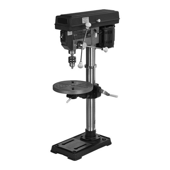
Summary of Contents for Central Machinery Central Machinery 13" Bench Drill Press
-
Page 2: Important Safety Information
Table of Contents Safety ............2 Maintenance ..........12 Specifications ..........6 Parts Lists and Diagrams ......14 Setup ............6 Warranty ............ 16 Operation ............ 9 WARNING SYMBOLS AND DEFINITIONS This is the safety alert symbol. It is used to alert you to potential personal injury hazards. Obey all safety messages that follow this symbol to avoid possible injury or death. -
Page 3: Extension Cord
General Tool Safety Warnings (cont.) 13. DON’T OVERREACH. Keep proper Table A: RECOMMENDED MINIMUM WIRE GAUGE footing and balance at all times. FOR EXTENSION CORDS (120 VOLT) 14. MAINTAIN TOOLS WITH CARE. Keep tools sharp EXTENSION CORD NAMEPLATE and clean for best and safest performance. Follow instructions for lubricating and changing accessories. -
Page 4: Grounding Instructions
Grounding Instructions TO PREVENT ELECTRIC SHOCK AND DEATH FROM INCORRECT GROUNDING WIRE CONNECTION READ AND FOLLOW THESE INSTRUCTIONS: 110-120 V~ Grounded Tools: Tools with Three Prong Plugs 1. In the event of a malfunction or breakdown, 6. Repair or replace damaged or worn cord immediately. grounding provides a path of least resistance for electric current to reduce the risk of electric shock. -
Page 5: Vibration Safety
If unreadable or missing, contact designed to filter out microscopic particles. Harbor Freight Tools for a replacement. (California Health & Safety Code § 25249.5, et seq.) 14. Avoid unintentional starting. 17. WARNING: Handling the cord on this product will Prepare to begin work before turning on the tool. -
Page 6: Specifications
Specifications Motor Power 3/4 HP - 16 speeds ranging from 220 to 3600 RPM Electrical Rating 120V~, 60Hz, 7.5A, Single-Phase Drill Chuck Capacity 7/64″ to 5/8″ Spindle Stroke 3-1/8″ Swing 13-1/4″ Column Diameter 2- 57/64″ Dry Table 11-1/2″ Diameter Table Slot 1/2″... -
Page 7: Installing The Chuck
Table and Support Arm to Column 1. Remove the Rack (2B) from the Column (1B) by 5. Firmly secure the Collar (19B) slackening off the Collar Set Screw (11B) and with the Set screw (11B). removing the Collar (19B). The rack is stowed 6. -
Page 8: Installing The Drive Belts
Installing the Drive Belts 1. Undo the Belt Tension Locking Knobs (18A) 3. Consult the chart inside the pulley cover on both sides of the head. Turn the Belt (or the Drill Speed chart in this manual), and Tension Lever (19A) clockwise to bring the install the belts in the positions corresponding Motor Pulley (11A) close to the Spindle Pulley to spindle/drill speed required. -
Page 9: Tool Set Up
Operating Instructions Read the ENTIRE IMPORTANT SAFETY INFORMATION section at the beginning of this manual including all text under subheadings therein before set up or use of this product. Tool Set Up TO PREVENT SERIOUS INJURY FROM ACCIDENTAL OPERATION: Turn the Power Switch of the tool off and unplug the tool from its electrical outlet before performing any procedure in this section. -
Page 10: Bit Installation
Changing Drill Speed Before changing the speeds, make sure the 3. Consult the chart inside the pulley cover and position machine is switched OFF and UNPLUGGED. the belts on the pulley’s according to the spindle which corresponds to the spindle/drill speed required. 1. -
Page 11: Workpiece And Work Area Set Up
Workpiece and Work Area Set Up 1. Designate a work area that is clean and well-lit. 9. FOR SMALL MATERIALS that cannot be clamped The work area must not allow access by children to the table, use a drill press vise. Make sure or pets to prevent distraction and injury. -
Page 12: Maintenance And Servicing
Maintenance and Servicing Procedures not specifically explained in this manual must be performed only by a qualified technician. TO PREVENT SERIOUS INJURY FROM ACCIDENTAL OPERATION: Turn the Power Switch of the tool off and unplug the tool from its electrical outlet before performing any procedure in this section. -
Page 13: Troubleshooting
Troubleshooting Problem Possible Causes Likely Solutions Tool will not start. 1. Cord not connected. 1. Check that cord is plugged in. 2. No power at outlet. 2. Check power at outlet. If outlet is unpowered, turn off tool and check circuit breaker. If breaker is tripped, make sure circuit is right capacity for tool and circuit has no other loads. -
Page 14: Parts Lists And Diagrams
Parts Lists and Diagrams Pulley and Spindle Parts List and Diagram Part # Description Code Part # Description Code “V” Belt M24 1505010 Arbor 1503007 Pulley Nut 1302025 Chuck 1503009A Spindle Pulley 1305009-02 Chuck Key 1503010A Pulley Insert 1302022 Wedge Drift 1503008 Ball Bearing 60203... - Page 15 Parts List and Diagram A - Head Note: All part numbers shown in this diagram have an “A” suffix Part # Description Code Part # Description Code Head w/pointer and trim 1302001A Feed Handle 1304005 Cable Clamp 1502014A Spindle Feed Shaft 1304002 Pan Head Screw M5x12...
-
Page 16: Limited 90-Day Warranty
Limited 90 Day Warranty Harbor Freight Tools Co. makes every effort to assure that its products meet high quality and durability standards, and warrants to the original purchaser that this product is free from defects in materials and workmanship for the period of 90 days from the date of purchase.