Table of Contents
Advertisement
Quick Links
Advertisement
Table of Contents
Troubleshooting

Related Manuals for Furuno FMD-811


Summary of Contents for Furuno FMD-811
- Page 1 RADAR REMOTE DISPLAY FMD-811 MODEL...
- Page 2 9 - 5 2 , A s h i h a r a - c h o , N i s h i n o m i y a , J a p a n Te l e p h o n e : 0 7 9 8 - 6 5 - 2 111 Te l e f a x : 0 7 9 8 - 6 5 - 4 2 0 0...
- Page 3 "NOTIICE", "CAUTION" and "WARNING" notices appear throughout this manual. It is the responsibility of the operator and installer of the equipment to read, understand and follow these notices. If you have any questions regarding these safety instructions, please con- tact a FURUNO agent or dealer. WARNING CAUTION...
- Page 4 NOTICE The installation must be done by a FURUNO representative or suitably qualified radar technician. Authorities require this. The mounting location must satisfy the following conditions: Useable temperature: -15 C to 55 C Out of direct sunlight Away from air conditioner vents...
-
Page 5: Table Of Contents
TABLE OF CONTENTS FOREWORD ... iv SPECIFICATIONS ... v 1. OPERATION 1.1 Control Description ... 1 1.2 Display Indications and Markers ... 2 1.3 Turning the Radar On and Off ... 2 1.4 Showing Radar Picture ... 3 1.5 Selecting the Range ... 3 1.6 Adjusting LCD Backlighting and Display Tone ... -
Page 6: Foreword
While this unit can be installed by the pur- chaser, any purchaser who has doubts about his or her technical abilities may wish to have the unit installed by a FURUNO rep- resentative or other qualified technician. The importance of a thorough installation can- not be overemphasized. -
Page 7: Specifications
SPECIFICATIONS FMD-811 1. Indication system PPI raster scan 2. Display 8-inch diagonal LCD, STN semi- transparent, yellow mode 3. Range scales (nm) Range, Ring Interval: 0.125(0.0625), 0.25(0.125), 0.5(0.125), 0.75(0.25), 1(0.25), 1.5(0.5), 2(0.5), 3(1), 4(1), 6(2), 8(2), 12(3), 16(4), 24(6), 36(12), 48(12), 64(16), 72(24) 4. - Page 8 15. Interface NMEA Input Own ship’s position: RMA>RMC>GLL (GLL is available Ver.5 and after.) Speed: RMA>RMC>VTG>VHW Heading (True): HDT>VHW>HDG>VHW>HDM Heading (Magnetic): HDM>VHW>HDG>VHW>HDM Course (True): RMA>RMC>VTG Course (Magnetic): VTG>RMA>RMC Waypoint (L/L, Range, Bearing): RMB>BWC>BWR Loran time difference: RMA>GLC>GTD Water depth: DPT>DBK, DBS, DBT Water temperature: MDA>MTW Time: ZDA XTE: RMB>XTE>APB...
- Page 9 EQUIPMENT LIST COMPLETE SET l l a INSTALLATION MATERIALS OPTION i f i t...
- Page 10 CONFIGURATION IEC 1162* IEC 1162* Video Sounder Heading Sensor Gyro Converter Gyro AD-100 *Equivalent to NMEA0183 Option viii (In/Out) (In) 5, 10, 15, 20 or 30m Radar External Alarm Buzzer OP03-136 Rectifier PR-62 10.2~31.2 VDC 115/230 VAC...
-
Page 11: Operation
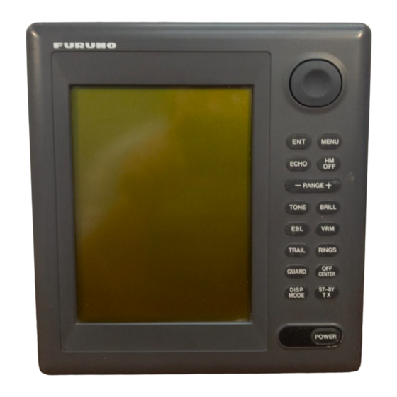
1. OPERATION 1.1 Control Description Registers selection on menus. Press to adjust gain, A/C RAIN, STC and A/C AUTO. Adjusts display tone. Turns the EBL on/off. Plots targets' trails. Sets guard zone area. Selects display mode; erases heading error indication. MENU ECHO RANGE... -
Page 12: Display Indications And Markers
1.2 Display Indications and Markers Range Range ring interval Off center CENTER Heading marker Guard zone area Cursor 0.675 1.3 Turning the Unit On and Off Turning the radar on Press the [POWER] key to turn the unit on or off. The control panel lights. Heading (requires heading data) HDG 326.8°... -
Page 13: Showing Radar Picture
1.4 Showing Radar Picture After the power is turned on,ST-BY (Stand- By) appears at the screen center. Press the [ST-BY TX] key to display radar picture in four gray tones according to echo strength. Press the [ST-BY TX] key again to set the radar in stand-by. - Page 14 GAIN AUTO AUTO RAIN AUTO OFF ON ECHO KEY TO EXIT Figure 1-4 Display for adjustment of GAIN, STC, A/C RAIN 2) Press the cursor pad to select item to ad- just. Current selection is circumscribed by dashed rectangle. 3) Press the [ENT] key. 3) Press the cursor pad to set level.
-
Page 15: Measuring The Range
How to adjust A/C RAIN The vertical beamwidth of the scanner is de- signed to see surface targets even when the ship is rolling. However, by this design the unit will also detect rain clutter (rain, snow, hail, etc.) in the same manner as normal tar- gets. -
Page 16: Measuring The Bearing
Target 0.675 220.9° range Figure 1-7 Measuring range by the VRM 1.10 Measuring the Bearing There are two ways to measure the bearing to a target: by the cursor, and by the EBL (Electronic Bearing Line). By cursor Operate the cursor pad to bisect the target with the cursor intersection. -
Page 17: Selecting The Presentation Mode
1.11 Selecting the Presentation Mode FMD-811 provides four presentation modes: head-up, course-up (course-up or waypoint- up; selectable on menu), north-up and true motion. Press the [DISP MODE] and [HM OFF] keys together to select a presentation mode. Each time the keys are pressed, if... - Page 18 Menu BACKLIGHT/BRILLIANCE MENU Select item and option keys. 1. Panel 1 2 3 4 2. Echo Trails ........Press HM-OFF to temporarily hide menu.
-
Page 19: Selecting The Display Mode
1.13 Selecting the Display Mode The display mode may be selected with the [DISP MODE] key. Four modes are avail- able (with navigation input): Normal, Nor- mal + Window, Normal + Nav Data, and Normal + Window + Nav Data. Window Display Nav Display **.** NM ***.* R... -
Page 20: The Window Display
1.14 The Window Display The window display appears at the bottom right (or left) 1/4 of the display. Two types of window displays are available: zoom and wide. Zoom doubles the size of the area se- lected by the operator, and wide (range-up) compresses and displays the entire radar pic- ture on the next higher range. - Page 21 3) Select Alarm Mode to IN or OUT. 4) Press the [ENT] key followed by the [MENU] key. Dashed line: no alarm Guard zone IN ALARM Figure 1-12 In and out alarms Setting the guard zone 1) Mentally create the guard zone you want to display.
-
Page 22: Suppressing Radar Interference
1.16 Suppressing Radar Interference Radar interference may occur when near an- other shipborne radar operating in the same frequency band as your radar. Its on-screen appearance is many bright dots either scat- tered at random or in the form of dotted lines extending from the center to the edge of the display. -
Page 23: Echo Trails
Cursor (1) Place cursor (2) Press [OFF CENTER] where desired. key; cursor location becomes screen center. Figure 1-15 Off centering the display 1.19 Echo Trails You can show the trails of targets in after- glow. This function is useful for alerting you to possible collision situations. -
Page 24: The Navigation Data Display
1.20 The Navigation Data Display Navigation data can be displayed at the screen bottom if the unit receives naviga- tion input in NMEA 0183 format. Naviga- tion data include • position in latitude and longitude or Lo- ran-C time differences (TDs) •... -
Page 25: Selecting Unit Of Measurement For Range
Distant echo Echo stretch OFF Figure 1-19 Echo stretch Turning echo stretch on or off 1) Press the [MENU] key. 2) Select Int/Noise Rej & ES and press the [ENT] key. 3) Select Echo Stretch. 4) ON or OFF. 5) Press the [ENT] key followed by the [MENU] key. -
Page 26: Deselecting Ranges
1.25 Deselecting Ranges The unit has 14 ranges, some which you may not require. You can deselect up to eight ranges as follows. 1) Press the [MENU] key. 2) Select Mode & Function and press the [ENT] key. 3) Select Range and press the [ENT] key. Active ranges appear in reverse video. -
Page 27: Outputting Cursor Position To Navigator
1.27 Outputting Cursor Position to Navigator Cursor position (NMEA0183 data sentence TLL) can be output to the navigator by press- ing and holding down the [HM OFF] key. 1.28 Displaying Cursor Position, Range and Bearing to Cursor The cursor data indication at the bottom of the display can show cursor position in lati- tude and longitude or the range and bearing from own ship to the cursor. -
Page 28: Interpreting The Display
2. INTERPRETING THE DISPLAY As an aid to navigation, radar can be a very valuable tool. No other electronic naviga- tion aid can give you the ability to spot ves- sels coming at you in the fog, or tell you the location of the inlet to the harbor in the pitch black of night. -
Page 29: Range Resolution
On the other hand, hulls made from wood or fiberglass return much weaker echoes. Vertical surfaces, such as a cliff, are good targets provided they face the radar. Con- versely, horizontal and smooth surfaces such as mudbanks, sandy beaches, and gently sloping hills make poor targets because they disperse rather than reflect most of the en- ergy that strikes them. - Page 30 oes may be observed on the display at double, triple or other multiples of the ac- tual range of the target as shown in Figure 2-4. Multiple reflection echoes can be re- duced and often removed by decreasing the sensitivity or properly adjusting the STC. True echo Target...
-
Page 31: Nautical Chart And Radar Picture
Blind and shadow sectors Funnels, stacks, masts, or derricks in the path of antenna may reduce the intensity of the radar beam. If the angle subtended at the scanner is more than a few degrees a blind sector may be produced. Within the blind sector small targets at close range may not be detected while larger targets at much greater ranges may be detected. -
Page 32: Maintenance & Troubleshooting
3. MAINTENANCE & TROUBLESHOOTING This chapter tells you how to keep your ra- dar in good working order. Before review- ing this chapter please read the safety information which follows. 3.1 Safety Information ELECTRICAL WARNING SHOCK HAZARD This equipment uses high voltage electric- ity which can shock, burn or cause death. -
Page 33: Preventative Maintenance
3.2 Preventative Maintenance Regular maintenance is important for good performance. Always keep the equipment as free as possible from dirt, dust, and water splashes. Make sure all screws securing the components are properly tightened. A maintenance program should be estab- lished and should at least include the items listed in Table 3-1. -
Page 34: Troubleshooting
3.4 Troubleshooting Table 3-2 contains simple troubleshooting procedures which you can follow to try to restore normal operation. If you cannot re- store normal operation, do not attempt to . . . check inside any unit of the radar system. Any repair work is best left to a qualified technician. -
Page 35: Self Test
3.5 Self Test The self test facility checks the keyboard, ROM and RAM for proper operation. You may run the test as follows. 1) Press the [MENU] key. 2) Select Self Check. The following display appears. [SELF TEST] KEY BOARD TEST Press each key. -
Page 36: Installation
4. INSTALLATION NOTICE The installation of this equipment requires certain electrical and mechanical skills. If the owner of the equipment has doubts about his or her technical abilities, we recommend that the equipment be installed by a qualified technician. 4.1 Mounting Considerations When selecting a mounting location for the unit keep in mind the following points. - Page 37 4 - 6 FIXING HOLES (10.79") (3.15") (0.71") (9.37") * :SERVICING CLEARANCE Figure 4-1 How to mount the unit 222(8.7") Cutting size for flushmount (5.12") *140 (5.51") (0.39") (3.94") (0.79") (0.71") *80 (3.15") about 10mm...
-
Page 38: Connections
MARINE RADAR TYPE SER.NO. DATE COMPASS SAFE DISTANCE EQUPMENT CLASS FURUNO ELECTRIC CO., LTD Ground terminal Connect ground wire between here and ship's ground. Figure 4-2 Display unit, rear view For the Connection to FR-7040R/7041R and MODEL 1941R, change R48 located near T1 from 12K ohms to 8.2K ohms on SPU-9180. - Page 39 Connection of Model 1833(C), 1933(C), 1943(C) Fabricate the interconnection cable (03S9298, 03S9299, 03S9318) as shown below. Con- nect the NH connector referring to the appropriate installation manual. Remove tape. Solder wire w/crimp-on lug (supplied) to braided shield. Vinyl tape Connect referring to appropriate installation manual.
- Page 40 Remarks 6P-6P (5 m) Distribution NAV data to the other 6P-6P (10 m) equipmet FMD-811 can output NAV data received from a navaid to an echosounder or video Remarks 6P-4P (5 m) plotter by making the modifications as be- 6P-4P (10 m) low.
-
Page 41: Installation Check List
RD-H RD-C RD-C SHIELD SHIELD 11. Turn on FMD-811 and confirm that NAV data in properly received at the ra- dar and external equipment. 4.4 Installation Check List After completing the installation it is a good idea to check for proper installation. Follow the checklist below and tick boxes to show proper completion. -
Page 42: Displaying The Installation Menus
picture. 3) Press the [ECHO] key. The following display appears. AUTO GAIN AUTO RAIN AUTO OFF ON ECHO KEY TO EXIT Figure 4-4 Display for adjustment of gain, STC (A/C SEA), A/C RAIN 4) Press the cursor pad to select GAIN- AUTO, if it is not already selected. -
Page 43: Entering Initial Settings
4.7 Entering Initial Settings 1) At the Installation Setup 1 menu, press the cursor pad to select Key Beep. (Key Beep turns on or off the buzzer which sounds when a key is pressed.) 2) Press the cursor pad to select OFF or 3) Press the [ENT] key. -
Page 44: Sweep Timing
4.9 Sweep Timing This adjustment ensures proper radar pic- ture, especially on short ranges. The radar measures the time required for a transmit- ted echo to travel to the target and return to the source. The received echo appears on the display based on this time. -
Page 45: Appendix A Installation Of Buffer Circuit
INSTALLATION OF BUFFER CIRCUIT The optional buffer circuit enables connection of the FMD-811 to the radars listed in Table 1. Table 1 Buffer circuit and applicable radars A.1 Assembling the Buffer Circuit Soldering of connector posts Solder appropriate I/O signal connector post (supplied) to both J12 and J22 on the BUFFER Board (03P9199). - Page 46 Attachment of double-sided tape (supplied) to BUFFER Board This should be done at room temperature. 1. Shorten leads of connector posts (soldered at previous section) on the underside of the BUFFER Board with pincers. 2. Wipe off foreign material from the underside of the BUFFER Board with a clean cloth. Peel off cover tape on one side of the double-sided tape and attach it to the underside of the board.
- Page 47 4. Make a hole in "OPTION" on the rear of the remote display and connect the signal cable (supplied with FMD-811) there. Connect the other end of the signal cable to J21 on the BUFFER Board. Seal the hole with sealing putty.
- Page 48 A.5 Troubleshooting . . . t t i i t c i t a A.6 Specifications Complete Set l l a i t a A – 4 . . .