Furuno 1623 Operator's Manual
Furuno marine radar user manual
Hide thumbs
Also See for 1623:
- Operator's manual (47 pages) ,
- Operator's manual (45 pages) ,
- Operator's manual (4 pages)
Table of Contents
Advertisement
Advertisement
Table of Contents
Troubleshooting

Related Manuals for Furuno 1623


Summary of Contents for Furuno 1623
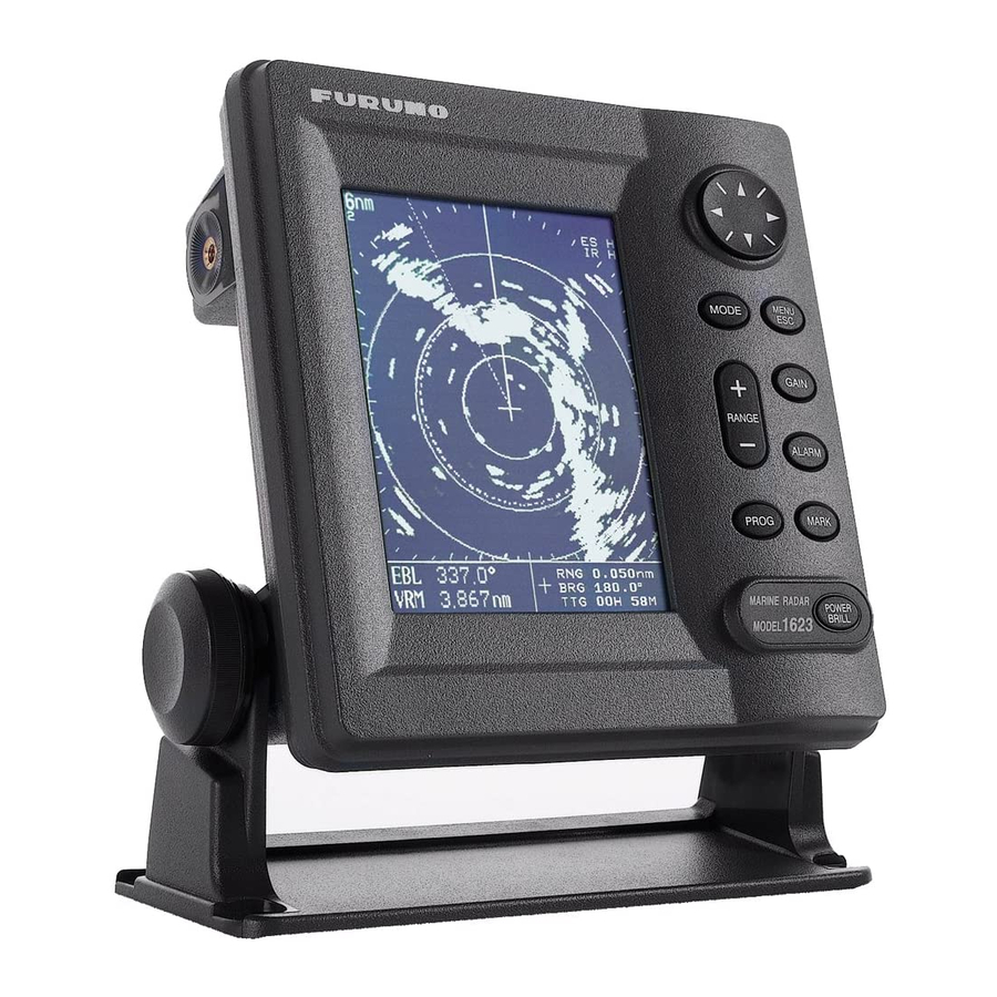
- Page 1 OPERATOR'S MANUAL MARINE RADAR MODEL 1623 MODEL www.furuno.co.jp...
- Page 3 (http://www.eiae.org/) for the correct method of disposal. How to discard a used battery Some FURUNO products have a battery(ies). To see if your product has a battery, see the chapter on Maintenance. Follow the instructions below if a battery is used. Tape the + and - terminals of battery before disposal to prevent fire, heat generation caused by short circuit.
- Page 4 WARNING LABEL A warning label is attached to the equipment. Do not remove the label. If the label is missing or damaged, contact a FURUNO agent or dealer about replacement. Name: Warning Label (1) WARNING Type: 86-003-1011-2 To avoid electrical shock, do not remove cover.
-
Page 5: Table Of Contents
TABLE OF CONTENTS FOREWORD... iv SYSTEM CONFIGURATION... v EQUIPMENT LISTS... vi 1. OPERATION... 1 1.1 Controls ... 1 1.2 Indications ... 2 1.3 Turning Power On/Off ... 3 1.4 Transmitting, Standby... 3 1.5 Adjusting Display Contrast, Brilliance . 4 1.6 Choosing the Range ... 4 1.7 Receiver Sensitivity... -
Page 6: Foreword
The main features of the MODEL 1623 are • Daylight viewing radar specially designed for small craft and sailing yachts. -
Page 7: System Configuration
SYSTEM CONFIGURATION ANTENNA UNIT RSB-0093 DISPLAY UNIT RDP-141 GPS RECEIVER GP-310B/320B WIND INDICATOR, SPEED INDICATOR NAVIGATOR or ECHO SOUNDER (NMEA 0183) RECTIFIER EXTERNAL PR-62 BUZZER XH3-BZ-L970 12-24 VDC : Standard supply 100/110/220/230 VAC, : Optional supply 1 , 50/60 Hz : Local supply... -
Page 8: Equipment Lists
EQUIPMENT LISTS Standard supply Name Type Antenna Unit RSB-0093 Display Unit RDP-141 CP03-25301 CP03-24910 Installation CP03-24920 Materials* CP03-24930 CP03-25101 Spare Parts* SP03-14301 *: See packing list at end of manual. Option Name Buzzer Assy. XH3-BZ-L970 Cable Assy. MJ-A7SPF0007-050 Cable Assy. MJ-A15A7F0004-005 Cable Assy. -
Page 9: Operation
1. OPERATION 1.1 Controls Display unit How to remove the hard cover Place your thumbs at the center of the cover, and then lift the cover while pressing it with your thumbs. -
Page 10: Indications
1.2 Indications Simulation mode Range Range ring interval ZOOM WATCH Zoom Watchman Guard zone Cursor Position Speed 45.0 EBL bearing 1.25 VRM range About the LCD This high quality LCD displays better than 99.9% of its picture elements. The remaining 0.01% may drop out or light, however this is not an indication of malfunction;... -
Page 11: Turning Power On/Off
[POWER/BRILL] key to start operation. However, the equipment may not work properly. Contact your dealer for advice. 6" LCD MARINE RADAR MODEL 1623 FURUNO ELECTRIC CO., LTD. ROM : OK RAM : OK Program No: 0359183-XX.XX XX.XX = Program version no. -
Page 12: Adjusting Display Contrast, Brilliance
1.5 Adjusting Display Contrast, Brilliance 1. Press the [POWER/BRILL] key momentarily to show the brilliance/contrast adjustment window. BRILL/CONTRAST TX/STBY - PRESS [MODE] CONT: BRILL: [MENU/ESC] : Exit. Brilliance/contrast adjustment window 2. Press ◄ or ► to adjust contrast. 3. Press ▲ or ▼ to adjust brilliance. 4. -
Page 13: Suppressing Sea Clutter
1. OPERATION 2. Press ▲ or ▼ to choose AUTO or MANU as appropriate. Automatic gain adjustment a) Press ► to open the automatic gain options window. MODERATE Automatic gain options b) Press ▲ or ▼ to choose ROUGH, MODERATE or CALM depending on sea conditions. -
Page 14: Suppressing Rain Clutter
Manual A/C SEA adjustment While observing the screen and the A/C SEA tuning bar, press ◄ or ► to set the A/C SEA. The setting range is 0-100. 4. Press the [MENU/ESC] key to finish. 1.9 Suppressing Rain Clutter The vertical beamwidth of the antenna is designed to see surface targets even when the ship is rolling. -
Page 15: Measuring The Bearing
1. OPERATION RNG 2.22nm BRG 45.62 2.91 TTG 02H21M range How to measure the range with the VRM and cursor 1.11 Measuring the Bearing The bearing to a target can be measured with the cursor and the EBL (Electronic Bearing Line). -
Page 16: Zoom
Choose manual SHIFT mode. Select where to shift Shifted display with the cursor. How the manual shift works To cancel the shifted display, open the Display Mode menu, choose NORMAL and then press the [MENU/ESC] key. 1.13 Zoom The zoom feature allows you to double the size of a selected area. -
Page 17: Heading Line
1. OPERATION 3. Press ► to show the options window for the item selected. For example, the illustration below shows the interference rejector options window. MEDIUM HIGH Interference rejector options 4. Press ▲ or ▼ to choose option desired. 5. Press ◄ to continue menu operation, or press the [MENU/ESC] key to register your selection and close the User menu. -
Page 18: Noise Rejector
2. Press ▲ or ▼ to choose INT REJECTION from page 1. 3. Press ► to open the options window. 4. Press ▲ or ▼ to choose OFF, LOW, MEDIUM or HIGH as appropriate. 5. Press the [MENU/ESC] key to finish. 1.17 Noise Rejector The noise rejector suppresses white noise, which appears on the screen as many dots... -
Page 19: Guard Alarm
1. OPERATION 1.20 Guard Alarm The guard alarm allows the operator to set the desired range and bearing for a guard zone. When ships, islands, landmasses, etc. violate the guard zone, the audio alarm sounds to call your attention. The alarm will sound on targets entering or exiting the zone depending on zone status after the alarm has been set. -
Page 20: Watchman
1.21 Watchman Watchman transmits the radar for one minute to check if a target has entered or exited the guard zone from the previous transmission. If no change is found, the radar goes into standby for the number of minutes set for the watchman feature. -
Page 21: Prog Key
1. OPERATION 1.23 PROG Key The [PROG] key acts as a menu shortcut key. You may use any User menu item except “SYSTEM MENU.” Using the PROG key 1. Press the [PROG] key. The options window corresponding to the item programmed appears. -
Page 22: Turning Navigation Data On/Off
1.25 Turning Navigation Data On/Off Navigation data appears on the bottom half of the screen as in the illustration below. You may turn the navigation data display on or off as shown below. Note: When the nav data is turned on with shift or zoom active, zoom or shift is cancelled. - Page 23 1. OPERATION GRAPHIC DISPLAYS 0.25 DIgital XTE Analog XTE (Bar moves right or left according XTE (Cross-Track Error) to XTE direction) GRAPHIC Speed 17.2 SPEED GRAPHIC Wind APP* 10.3 Speed WIND GRAPHIC Waypoint 03 Destination Rng 0.19nm Brg 321 XTE 0.00nm Cse 333 waypoint data:...
-
Page 24: System Menu
1.27 System Menu The System menu mainly contains items which once set do not require frequent adjustment. You may display this menu by choosing “SYSTEM MENU” from page 3 of the User menu and then pressing ►. PAGE 1 SYSTEM MENU LANGUAGE English RANGE UNIT... - Page 25 1. OPERATION PANEL DIMMER: You may adjust panel backlighting from among OFF, LOW, MEDIUM and HIGH. HUE: The default hue setting (DAY) display is most suitable for daytime viewing. For nighttime viewing you may reverse this arrangement (NIGHT). TRIPLOG RESET: You may reset distance run to zero by choosing YES.
-
Page 26: Maintenance, Troubleshooting
2. MAINTENANCE, TROUBLESHOOTING WARNING ELECTRICAL SHOCK HAZARD Do not open the equipment. Only qualified personnel should work inside the equipment. 2.1 Maintenance Regular maintenance is important for good performance. A maintenance program should be established and should at least include the items listed in the table below. Period Item Fixing bolts for... -
Page 27: Replacing The Fuse
2.2 Replacing the Fuse The fuse (5 A) in the power cable protects the equipment against reverse polarity of ship’s mains, overcurrent, and equipment fault. If the fuse blows, find the cause before replacing it. Use the proper fuse. Use of a wrong fuse may cause serious damage to the equipment and void the warranty. -
Page 28: Diagnostics
2. MAINTENANCE, TROUBLESHOOTING 2.4 Diagnostics If you feel that your unit is not working properly, conduct the appropriate diagnostic test, display unit or antenna unit, to find the possible cause. If you cannot restore normal operation, contact your dealer for advice. Display unit 1. -
Page 29: Test Pattern
When the synchro belt has worn out, the sweep is not synchronized with antenna rotation, which results in an abnormal picture. When you suspect that the synchro belt has worn out, contact a FURUNO agent or dealer about replacement. (Type: 40 S2M 266UG, Code No: 000-808-743) FOUR-TONE... -
Page 30: Installation
3. INSTALLATION 3.1 Antenna Unit Installation Mounting considerations When selecting a mounting location for the antenna unit keep in mind the following points: Install the antenna unit on the hardtop, radar arch or on a mast on an appropriate platform. (For sailboats, a mounting bracket is optionally available.) It should be placed where there is a good all-round view with, as far as possible, no part of... - Page 31 3. Using the hexagon head bolts, flat washers and spring washers removed at step 1, fasten the antenna unit to the platform. The torque should be 19.6-24.5 N m. Antenna base Effective thread length 15 mm Flat washer Spring washer Hexagon head bolt (M10 x 20 or M10 x 25) Platform thickness...
- Page 32 3. INSTALLATION 7. Referring to the figure below, fasten the shield cable with a screw (M4x10) on the chassis to ground the unit. Connect 9 pin connector here (J801). How to connect the antenna cable to the antenna unit 8. Attach the EMI core to the antenna cable. Set the EMI core fixing plate to the EMI core.
-
Page 33: Display Unit Installation
M8 x 20 Mounting plate M8 x 20 Bracket (1) Fixing plate Bracket (2) M8 x 20 (A) Assembling the mounting bracket M10 x 25 (B) Fastening antenna to mounting bracket How to assemble the optional mounting bracket and mount the antenna 4. -
Page 34: Wiring
Note: This procedure requires making a hole in the display unit, which can affect watertightness. FURUNO cannot guarantee watertight integrity after this modification is made. 1. Detach the rear panel and place it out side up on a workbench. -
Page 35: Adjustments
Display unit, rear view 3. Close the rear panel, making sure the gasket is correctly positioned. 4. Plug in the connector of the external buzzer to J6 on the DU Board. 5. Seal the hole with sealing compound. 6. Fix the buzzer to the location desired with two tapping screws. - Page 36 3. INSTALLATION 8. Press ▲ to select YES, and the display now looks as below. Heading Line Message HEADING LINE ADJUSTMENT BY ’ ’ AND ’ ’ KEYS. THEN PUSH MODE KEY TO SET. Heading adjustment display 9. Visually identify a suitable target (for example, ship or buoy) at a range between 0.125 to 0.25 miles.
-
Page 37: Magnetron Heater Voltage
NMEA port setup, GPS WAAS setup The NMEA port can function as an input port or input/output port. If you are using the GP-320B, turn on the GPS WAAS feature. 1. Show the Installation menu and then press ▼ to choose NMEA PORT. 2. -
Page 38: Menu Tree
MENU TREE MENU/ESC TX/ST-BY (TX, ST-BY ) INT REJECTION (OFF, LOW , MEDIUM, HIGH) ECHO STRETCH ( OFF , LOW, HIGH) FTC ( OFF , ON) NOISE REJECTION (OFF, LOW , HIGH) WATCHMAN TIME ( OFF , 5, 10, 20 min) HDG LINE OFF (Temporarily turns off heading line.) ECHO TRAIL ( OFF , 30 s;... - Page 39 This page is intentionally left blank.
-
Page 40: Specifications
Bandwidth Duplexer 3.10 Time of Heat-up DISPLAY UNIT Picture Tube Display Pixels MODEL 1623 PPI Daylight display, raster scan, 4 tones in monochrome 0.3 μs (medium) 0.8 μs (long) 1200 Hz nominal 600 Hz nominal 16 m 6.7° 22 m Within 1°... - Page 41 Range, Range Interval, Number of Rings Range (nm/km) 0.125 Ring Interval 0.0625 0.125 0.125 0.25 0.25 0.5 Number of Rings Range unit: nm/sm/km selectable, 0.125: nm/sm only, 24: km only Markers Alphanumeric Indications Range, Range Ring Interval, Display Mode (HU), Input Sentences Output Sentences ENVIRONMENTAL CONDITION...
-
Page 42: Packing List
PACKING LIST MODEL1623-J-0/10/15/20,MODEL1623-E-0/10/15/20 N A M E ユニット UNIT 空中線部 ANTENNA UNIT 指示部 DISPLAY UNIT 空中線部工材 ANTENNA UNIT INSTALLATION MATERIALS 空中線部工材 INSTALLATION MATERIALS 工事材料 INSTALLATION MATERIALS ケーブル組品MJ SIGNAL CABLE ASSY. ケーブル組品MJ SIGNAL CABLE ASSY. ケーブル組品MJ SIGNAL CABLE ASSY. 図書 DOCUMENT 技適認証要領 APPLICATION GUIDE 1.(*)印のケ-ブル組品は、不用又は、10m,15m,20mの長さから選択できます。... - Page 43 D - 1...
- Page 44 D - 2...
- Page 45 D - 3...
- Page 48 : +81-(0)798-65-4200 Printed in Japan All rights reserved. Pub. No. OME-35100-G3 (YOSH ) MODEL1623 The paper used in this manual is elemental chlorine free. ・FURUNO Authorized Distributor/Dealer A : OCT G3 : MAR . 03, 2011 *00080939214* *00080939214* *00080939214* *00080939214*...