Table of Contents
Advertisement
Enhanced Ground Proximity Warning Systems
CAGE CODE: 97896
SCALE: NONE
EGPWS LINE MAINTENANCE MANUAL
MK V
MK VI
MK VII
MK VIII
MK XXII
Line Maintenance Manual
Document No: 060-4199-180, Rev G
Release date: 29 Mar 2010
Honeywell International, Inc.
Redmond, Washington 98073-9701
SIZE: A
DWG NO.: 060-4199-180
REV:
G
SHEET 1 of 68
Advertisement
Table of Contents
Troubleshooting

Related Manuals for Honeywell MK V


Summary of Contents for Honeywell MK V
- Page 1 EGPWS LINE MAINTENANCE MANUAL MK V MK VI MK VII MK VIII MK XXII Enhanced Ground Proximity Warning Systems Line Maintenance Manual Document No: 060-4199-180, Rev G Release date: 29 Mar 2010 Honeywell International, Inc. Redmond, Washington 98073-9701 CAGE CODE: 97896...
- Page 2 “need to know” basis. Your use of this document is strictly limited to a legitimate business purpose requiring the information contained therein. Your use of this document constitutes acceptance of these terms. Typed signatures constitute approval. Actual Signatures are on file at Honeywell in Redmond, WA. DRAWN R. Halbert...
- Page 3 TOC and added the following RAAS-related sections: (1) Section 2.2.15 (2) “Application Software Version Invalid” and “RCD Failed” (MK V/VII) aural annunciations to Table 3-2. (3) Sections 3.8.42 and 3.8.43 (4) Appendix C Reason 01 Severity 10 1) Deleted “Revisions Status of Sheets Index” table on 27 SEP 04 K.
- Page 4 EGPWS LINE MAINTENANCE MANUAL REVISIONS DESCRIPTION DATE APPROVED Section 3.3.2 – added RAAS maintenance message to short 01 FEB 05 S. Wright Level 1 Self-Test sequence and two notes, one to ensure 03 FEB 05 K. Christofferson RAAS messages only occur if RAAS is activated and one to explain the GPS NOT NAVIGATING enunciation.
-
Page 5: Table Of Contents
Weather Radar AutoTilt (MK V and MK VII only) ..................16 2.2.14 System Display and Annunciation......................17 2.2.15 Runway Awareness and Advisory System (option for MK V and MK VII only).........17 2.2.16 Stabilized Approach Monitor (option for MK V and MK VII only) ..............17 2.2.17 Altimeter Monitor (option for MK V and MK VII only) ................ - Page 6 RAAS EnABLE Discrete (MK V and MK VII Only) ..................49 3.8.44 RAAS Inhibit Discrete (MK V and MK VII Only) ..................49 3.8.45 Stabilized Approach Monitor Enable Discrete (MK V and MK VII Only) ...........50 3.8.46 Stabilized Approach Monitor Inhibit Discrete (MK V and MK VII Only)............. 50 3.8.47 Low Airspeed Monitor Inhibit Discrete (MK V –...
- Page 7 EGPWS LINE MAINTENANCE MANUAL 5.1 G ................................57 ENERAL REMOVAL/INSTALLATION..........................57 6.1 EGPWC.................................57 6.1.1 Removal..............................57 6.1.2 Installation ..............................57 6.2 C (MK VI, MK VIII, MK XXII ) ................57 ONFIGURATION ODULE ONLY 6.2.1 Removal..............................57 6.2.2 Installation ..............................57 6.3 D )......................58 ISPLAY...
-
Page 8: Introduction
1.2 APPLICABILITY This manual is applicable to the MK V, MK VI, MK VII, MK VIII, and MK XXII EGPWS with the following part numbers and general description:... -
Page 9: Reference Documents
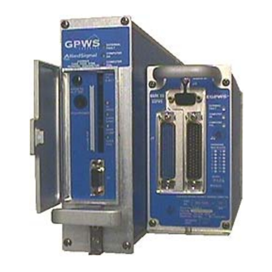
EGPWS LINE MAINTENANCE MANUAL MK V & MK VII EGPWC (left) and MK VI, MK VIII, MK XXII EGPWC (right) Figure 1-1 - Enhanced Ground Proximity Warning Computers 1.3 REFERENCE DOCUMENTS The following documents are identified as additional EGPWS references: MK V and MK VII: 965-0976-603 ..Product Specification for the EGPWS (MK V and MK VII) -
Page 10: Description And Operation
EGPWS LINE MAINTENANCE MANUAL DESCRIPTION AND OPERATION 2.1 GENERAL SYSTEM DESCRIPTION The purpose for the Enhanced Ground Proximity Warning System (EGPWS) is to help prevent accidents caused by Controlled Flight Into Terrain (CFIT), obstacles, or severe windshear. The Enhanced Ground Proximity Warning Computer (EGPWC) accepts a variety of aircraft sensors and system inputs and applies alerting algorithms to provide the flight crew with aural messages and visual annunciations when the boundaries of alerting envelopes are exceeded. -
Page 11: Enhanced Ground Proximity Warning Computer (Egpwc)
Proximity Warning Computer (EGPWC). The MK V and MK VII EGPWC are digitally controlled computers housed in a 2 MCU ARINC 600-6 form factor chassis intended for Air Transport type aircraft. Installation configuration is defined by program pin strapping in the aircraft. -
Page 12: Mode 5 - Descent Below Glideslope
EGPWS LINE MAINTENANCE MANUAL provides “TOO LOW TERRAIN” or “TOO LOW FLAPS” depending on airspeed. Mode 4C provides “TOO LOW TERRAIN”. EGPWS alert lights are illuminated during these alerts. 2.2.5 MODE 5 - DESCENT BELOW GLIDESLOPE Mode 5 provides audio and visual alerts for excessive glideslope deviation when the aircraft descends below the glideslope beam on front-course ILS approaches. - Page 13 EGPWS LINE MAINTENANCE MANUAL MODEL CALLOUT DESCRIPTION VIII XXII 500 TONE Provides 2 second 960 Hz tone at descent below 500 • • feet SMART “FIVE HUNDRED” At descent below 500 feet (only) during non-precision • • • • • approach “FIVE HUNDRED”...
-
Page 14: Mode 7 - Windshear Detection (Optional For Mk V/Vii Only)
The TCF function is enhanced in all fixed-wing models (beginning with release –210-210 for the MK V/VII) with the addition of a Runway Field Clearance Floor (RFCF) alerting function. RFCF is based on current aircraft location, destination runway center point position, and Geometric Altitude or altitude Above Sea Level (ASL) relative to the destination runway. -
Page 15: Terrain Alerting And Display (Optional)
The EGPWS Runway Database consists of data records for all airport runways offered for the coverage provided by the Terrain Database. For the MK V and MK VII, all hard surface runways in the world 3500 feet or greater in length are supported. -
Page 16: Peaks Display Mode (Optional)
EGPWS LINE MAINTENANCE MANUAL The Obstacle Database (in MK V and MK VII -204-204 and later, and MK VI, MK VIII and MK XXII) is a separate file included within the terrain database. Both files are loaded into the EGPWS in the terrain database PCMCIA card. -
Page 17: System Display And Annunciation
2.2.17 ALTIMETER MONITOR (OPTION FOR MK V AND MK VII ONLY) The Altimeter Monitor function offers significant safety enhancements for aircraft equipped with Honeywell’s MK V or MK VII Enhanced Ground Proximity Warning Systems (EGPWS). Honeywell’s Altimeter Monitor is a software enhancement hosted in the EGPWS Unit. -
Page 18: Takeoff Flap Configuration Monitor (Option For Mk V And Mk Vii Only)
Configuration Monitor is a software enhancement hosted in the EGPWS Unit. Takeoff Flap Configuration Monitor uses GPS position data, Flap angle inputs, and the Honeywell EGPWS Database to provide aural alerts that supplement flight crew awareness of improper flap setting when the aircraft is aligned on a runway prior to takeoff. -
Page 19: Lamp Format
EGPWS LINE MAINTENANCE MANUAL 2.2.21 LAMP FORMAT The EGPWS contains two different caution/warning lamp illumination formats as described below. Lamp Format 1 provides EGPWS warning (red) and caution (amber) alert lamp drive logic such that: • Only a Mode 5 “Glideslope” alert will activate the caution lamp output (amber). •... -
Page 20: System Maintenance
EGPWS LINE MAINTENANCE MANUAL 2.3 SYSTEM MAINTENANCE 2.3.1 MAINTENANCE PHILOSOPHY The EGPWS is an “on-condition” only maintenance system. No scheduled maintenance is required. This is accomplished by both continuous Built-In-Test (BIT) and event initiated test functions. Event initiated test refers to both power-up tests and manually activated Self-Tests. -
Page 21: Egpwc Front Panel
2.3.4.4 FRONT PANEL PCMCIA INTERFACE For the MK V and MK VII, a PCMCIA card slot is provided in the front panel. For the MK VI, MK VIII, and MK XXII the PCMCIA interface utilizes an external PCMCIA interface called a “SmartCable” connected to the front panel Test Connector. -
Page 22: Self-Test Functions
Self-Test aural is heard over the cockpit speaker, cockpit interphone system, or through the headphone jack on the EGPWC front panel (MK V and MK VII only). Details of these Self-Test levels are provided in Fault Isolation Section 3. -
Page 23: Fault Isolation (Troubleshooting)
EGPWS LINE MAINTENANCE MANUAL FAULT ISOLATION (TROUBLESHOOTING) 3.1 GENERAL The troubleshooting methods provided in this section identify system and sensor or subsystem faults to the lowest level possible. Additional fault isolation in the installation or associated sensors or subsystem should be performed using the aircraft installation and wiring diagrams and other supporting documentation in accordance with established maintenance procedures. -
Page 24: Level 1 Self-Test - Go/No Go Test
Action: removing or replacing the EGPWC for repair (see Removal/Installation section) Enunciation: “AIRCRAFT CONFIGURATION DATA BASE CRC FAILED” (MK V or MK VII only) Probable Cause: EGPWC internal configuration database error. Pull power to the EGPWS for one minute and cycle power to clear all potential faults before... -
Page 25: Short Level 1 Self-Test
EGPWS LINE MAINTENANCE MANUAL POSSIBLE SELF-TEST PREAMBLE RESULTS Enunciation: “CONFIGURATION MODULE NOT PROGRAMMED” (MK VI, MK VIII, MK XXII only) Probable Cause: The Configuration Module is not programmed. Action: Program the Configuration Module. See Maintenance Practices section. Enunciation: “CONFIGURATION MODULE NOT COMPATIBLE” (MK VI, MK VIII, MK XXII only) Probable Cause: The Configuration Module is not compatible with the EGPWC h/w or s/w or it’s faulty. -
Page 26: Long Level 1 Self-Test
“EXTERNAL FAULT” LED on the EGPWC front panel. Note that for the EGPWS/GNSSU (-060 MK V/VII), both internal and external fault lights will be lit if there is a problem with the integral GNSSU subsystem. -
Page 27: Current Faults - Internal
APPLICATION DATABASE FAILED (DSP or CRC) TERRAIN DATABASE FAILED (CRC or Runway or Mag. Var.)*** TERRAIN DATABASE NOT COMPATIBLE ENVELOPE MODULATION DATABASE FAILED CONFIGURATION DATABASE FAILED (MK V/VII) APPLICATION DATABASE FAILED (MK VI/VIII/XXII ) CONFIGURATION DATABASE AAC DATA FAULT SYSTEM OR MODE TASK FAILED... - Page 28 EGPWS LINE MAINTENANCE MANUAL TABLE 3-3: CURRENT FAULTS - EXTERNAL (EXAMPLES) FAULT EXAMPLE REASON ARINC 429 Bus Fault GPS BUS 1 INACTIVE No expected input labels received for more than 4 seconds ARINC 429 Signal ILS BUS 1 GLIDESLOPE FAULT FW The SSM of the input data indicates Fault Failure/Warning...
- Page 29 EGPWS LINE MAINTENANCE MANUAL TABLE 3-4: LEVEL 2 SELF-TEST - EXTERNAL FAULTS THE FOLLOWING EXTERNAL FAULTS ARE AVAILABLE IN LEVEL 2 SELF-TEST: Enunciation: “<BUS> Inactive” Example: GPS BUS 1 Inactive Input source not powered or a wiring problem exists between source LRU and the Probable Cause: EGPWC.
- Page 30 EGPWS LINE MAINTENANCE MANUAL THE FOLLOWING EXTERNAL FAULTS ARE AVAILABLE IN LEVEL 2 SELF-TEST: Description: SELF-TEST INVALID (WinVIEWS ONLY) Probable Cause: Electrical short at the Self-Test input. Action: Verify wiring from the Self-Test discrete. Enunciation: “MOMENTARY TERRAIN SELECT 1 (or 2) INVALID” Probable Cause: Electrical short at the Terrain Select inputs.
- Page 31 EGPWS LINE MAINTENANCE MANUAL TABLE 3-5: GENERAL FAILURE CODE IDENTIFIERS For example, if the Computed Airspeed from Air Data Computer #1 is failed (i.e., SSM = Fail Warning), the following messages would be enunciated: “CURRENT FAULTS” “EGPWC OK” “EXTERNAL FAULTS” “AIR DATA BUS 1 COMPUTED AIRSPEED FAULT”...
- Page 32 (see Maintenance Practices) or replaced (see Removal/Installation section). If the unit is a MK V or MK VII with integral GNSSU (-060 part number), and external faults are indicated on GPS signals (e.g., GPS BUS 1 LATITUDE FAULT), an internal fault may exist. In this case both fault lights will be on and the message INTERNAL GPS FAULT will also be indicated.
-
Page 33: Level 3 Self-Test - System Configuration
Configuration Software Version (only for PNs 965-0976-XXX or 965-1076-XXX) Terrain Database Version Envelope Modulation Database Version Boot Code Version RAAS RCD Part Number (MK V/VII and RAAS enabled only) Aircraft Type Audio Menu Altitude Callout Menu All other selected options from installation configuration. Note that only those features that are enabled or disabled from the basic configuration are enunciated. - Page 34 EGPWS LINE MAINTENANCE MANUAL THE FOLLOWING INFORMATION IS GIVEN IN THE LEVEL 3 SELF-TEST: “IRS 1 ATTITUDE MODE SELECTED” “ MODE 6 INOP-NO Decision Height” (approaching minimums in menu). “STEEP APPROACH ACTIVATED” “STEEP APPROACH ENABLED” “STEEP APPROACH SELECTED” “VISUAL SUPPRESS ENABLED” “ALTERNATE VOLUME 1 SELECTED”...
- Page 35 EGPWS LINE MAINTENANCE MANUAL THE FOLLOWING INFORMATION IS GIVEN IN THE LEVEL 3 SELF-TEST: “GPS ALTITUDE REF WGS84 SELECTED” “AUTOROTATION CALLOUT X SELECTED” (MK XXII) “NORMAL POPUP RANGE X SELECTED” (MK XXII) “LOW ALTITUDE POPUP RANGE X SELECTED” (MK XXII) “MODE 6B ALWAYS ON SELECTED”...
-
Page 36: Level 4 Self-Test - Fault History
EGPWS LINE MAINTENANCE MANUAL 3.6 LEVEL 4 SELF-TEST - FAULT HISTORY Level 4 Self-Test provides enunciation of the faults recorded over the last 10 flight legs. Level 4 Self-Test is initiated by pressing the cockpit Self-Test button within 3 seconds of the end of Level 3 Self-Test. If any faults were recorded in the last ten flight legs then voice sequence as described in the following table will be enunciated. -
Page 37: Level 5 Self-Test - Alert History
EGPWS LINE MAINTENANCE MANUAL 3.7 LEVEL 5 SELF-TEST - ALERT HISTORY Level 5 Self-Test provides enunciation of the alerts (cautions and warnings) recorded over the last 10 flight legs. Level 5 Self-Test is initiated by pressing the cockpit Self-Test button within 3 seconds of the end of Level 4 Self- Test. -
Page 38: Arinc 552 / Alt 55 Radio Altitude Validity Flag Discretes
EGPWS LINE MAINTENANCE MANUAL 3.8.1 ARINC 552 / ALT 55 RADIO ALTITUDE VALIDITY FLAG DISCRETES Three Radio Altitude validity flags may be used by the EGPWS, one for each of the three possible ARINC 552 or ALT 55 Radio Altimeters inputs. Type Validity from ARINC 552 or ALT 55 Radio Altimeter. -
Page 39: Gnd Landing Flap Discrete Or Flap Override
EGPWS LINE MAINTENANCE MANUAL 3.8.4 GND LANDING FLAP DISCRETE OR FLAP OVERRIDE Type: Supplied by Flap or Flap selector handle switch. This input can be paralleled with, or used exclusively by a Flap Override Switch if an alternate source of Flap Position is used. Signal Status: Landing Flaps or Not Landing Flaps Fault monitoring: Indication of landing flaps selected for more than 60 seconds at airspeeds above 250 knots will result in a flap switch fault which will cause a GPWS INOP indication. -
Page 40: Flap Position Discretes
Steep Approach is to be used, and can be permanently enabled. Discrete #2 should be selected in flight when starting a steep approach, it should not be permanently selected. On ground Self-Test is inhibited if Steep Approach is active. 3.8.8.1 STEEP APPROACH DISCRETE #1 (MK V AND MK VII ONLY) Type: Steep Approach Enabled... -
Page 41: Gnd Ils Tuned Discrete
EGPWS LINE MAINTENANCE MANUAL 3.8.8.2 STEEP APPROACH DISCRETE #2 Type: Steep Approach Selected Signal Status: Steep Approach Selected or Not Selected Level 6 Audio readout Selected => “Steep Approach Selected” Steep Approach Discrete #2 Not Selected => “Steep Approach Not Selected”... -
Page 42: Gnd Glideslope Inhibit Discrete
EGPWS LINE MAINTENANCE MANUAL 3.8.12 GND GLIDESLOPE INHIBIT DISCRETE Type: Switch for inhibit of Glideslope mode Signal Status: Glideslope Inhibit or Not Inhibit Fault monitoring: Mode 5 will be disabled and “Glideslope” will not be enunciated during cockpit Self-Test and the long vocabulary test if inhibited. -
Page 43: Mode 6 Volume Control Discrete
“Mode 6 Low Volume” Mode 6 Low Volume Discrete Normal => “Mode 6 Normal Volume” 3.8.17 CALLOUTS ENABLE DISCRETE (MK V AND MK VII ONLY) Type: Mode 6 Altitude callouts enable switch Signal Status: Callouts Enable or Callouts Disable with optional Minimums only Level 6 Audio readout Voice Enabled =>... -
Page 44: Aoa Validity Discretes (Mk V And Mk Vii Only)
EGPWS LINE MAINTENANCE MANUAL 3.8.20 AOA VALIDITY DISCRETES (MK V AND MK VII ONLY) Two AOA validity discretes may be used by EGPWS, one for each source of AOA. Input will come from either an AOA Indication System or a Stall Warning Computer, depending on the type being used by the aircraft. -
Page 45: Weather Radar On/Off
“Weather 2 On” WXR #2 On Discrete Off => “Weather 2 Off” 3.8.25 LOCALIZER VALIDITY DISCRETES (MK V AND MK VII ONLY) Two Localizer validity discretes may be used by EGPWS, one for each possible ARINC 547 Localizer Receiver input. Type: Validity from ARINC 547 Localizer receiver. -
Page 46: Barometric Altitude Rate Validity Discretes
EGPWS LINE MAINTENANCE MANUAL 3.8.28 BAROMETRIC ALTITUDE RATE VALIDITY DISCRETES Two Barometric Altitude Rate validity discretes may be used by EGPWS, one for each possible barometric rate sensor. Type: Validity from barometric rate sensor. Signal Status: Valid or Invalid Level 6 Audio readout Valid =>... -
Page 47: Magnetic Heading Validity Discrete
False => “AOA Vane Heater Off” 3.8.35 PLI DESELECT SWITCH DISCRETES (MK V AND MK VII ONLY) PLI deselect switch discretes may be used by EGPWS for de-activating the PLI select relays to remove EGPWS PLI indication from the ADI. -
Page 48: Tactical Select Discrete
EGPWS LINE MAINTENANCE MANUAL 3.8.37 TACTICAL SELECT DISCRETE Tactical Select discrete may be used by EGPWS for an indication that the Tactical Select switch has been pressed. Type: momentary make/break switch Signal Status: Tactical Select Selected or Not Selected Level 6 Audio readout Selected =>... -
Page 49: Weight On Wheels Discrete
GPWS Inhibit => “GPWS Inhibit” GPWS Inhibit Discrete Not Inhibit => “GPWS Not Inhibit” 3.8.43 RAAS ENABLE DISCRETE (MK V AND MK VII ONLY) Type: Discrete for enabling RAAS functionality Signal Status: RAAS Enabled or Disabled Level 6 Audio readout True =>... -
Page 50: Stabilized Approach Monitor Enable Discrete (Mk V And Mk Vii Only)
EGPWS LINE MAINTENANCE MANUAL 3.8.45 STABILIZED APPROACH MONITOR ENABLE DISCRETE (MK V AND MK VII ONLY) Type: Discrete for enabling Stabilized Approach Monitor functionality Signal Status: Approach Monitor Enabled or Disabled Level 6 Audio readout True => “Approach Monitor Enabled”... -
Page 51: Maintenance Practices
4.2.2 LOADING A DATABASE A database is loaded into the EGPWC via the PCMCIA card slot in the front panel in the MK V and MK VII. In the MK VI, MK VIII, and MK XXII a “Smart Cable” data-loader is connected to the Test connector on the front panel. -
Page 52: Flight History Downloading
For the MK V or MK VII, ensure the notch on the bottom of the PCMCIA Card is in the down position. Push the card in carefully until the PUSH TO EJECT button on the front Panel is fully extended. This will be when the face of the button is nearly level with the rear of the inserted PCMCIA Card. -
Page 53: Transcription Of The Pcmcia Card
9. Remove the PCMCIA Card, For the MK V or MK VII, depress the PUSH TO EJECT button on the EGPWC front panel. For the MK VI or MK VIII, and MK XXII, carefully grasp the card and pull from the Smart Cable. -
Page 54: Programming The Configuration Module (Mk Vi, Mk Viii, Mk Xxii Only)
EGPWS LINE MAINTENANCE MANUAL 4.4 PROGRAMMING THE CONFIGURATION MODULE (MK VI, MK VIII, MK XXII ONLY) Programming the EGPWS Configuration Module is accomplished using WinVIEWS on a PC connected to the EGPWC via the RS-232 interface. Prior to this activity, the necessary and desired configuration should be determined based on the MK VI, MK VIII, or MK XXII Installation Design Guide referenced in Section 1.3. -
Page 55: Configuration Module Reprogramming (Mk Vi, Mk Viii, Mk Xxii Only)
EGPWS LINE MAINTENANCE MANUAL 4.4.1 CONFIGURATION MODULE REPROGRAMMING (MK VI, MK VIII, MK XXII ONLY) Reprogramming the EGPWS Configuration Module is accomplished similar to the programming process above. Prior to reprogramming, the desired new configuration should be determined based on the MK VI, MK VIII, or MK XXII Interface Design Guide (IDG) document referenced in Section 1.3. - Page 56 EGPWS LINE MAINTENANCE MANUAL An example CUW command/data string, its definition, and the corresponding CWR list is provided below. CUW command/data string: CFG > CUW 0/15 2 3 2 0 0 3 95 1 0 0 0 0 0 0 0/ Above Configuration defined: Category 1 Aircraft/Mode Type: Category 2 Air Data Source:...
-
Page 57: Servicing
EGPWS LINE MAINTENANCE MANUAL SERVICING 5.1 GENERAL The EGPWS does not require any servicing. REMOVAL/INSTALLATION 6.1 EGPWC 6.1.1 REMOVAL 1. Remove power to the EGPWC. 2. (MK VI, MK VIII, and MK XXII only) Disconnect aircraft connectors from the front of the unit. 3. -
Page 58: Display Switching Relays (If Installed)
All EGPWS Ground Tests are developed by the installer to meet aircraft specific interfaces. Examples of Ground Test are available from Honeywell via the EGPWS website. To obtain a copy of a sample Ground Test Procedure, please visit www.egpws.com, select the Installation Information page, then select the Ground and Flight Test Procedures sub-page. -
Page 59: Inspection/Check
EGPWS LINE MAINTENANCE MANUAL INSPECTION/CHECK 8.1 GENERAL The EGPWS does not require any specific periodic inspection or checks. The system should be inspected for integrity and checked for wear/tear during the course of routine aircraft maintenance inspections. CLEANING/PAINTING 9.1 GENERAL The EGPWS does not contain any elements that required cleaning or painting on the aircraft. -
Page 60: Appendix A: Winviews
EGPWS LINE MAINTENANCE MANUAL 11 APPENDIX A: WINVIEWS WinVIEWS (Windows Virtual Interface to the Enhanced Warning System) is a software tool developed by Honeywell to monitor or view values within the EGPWC, and perform certain test interface functions. Overview: The WinVIEWS software provides a monitor function that does not alter the operation of the EGPWS. -
Page 61: Appendix B: Troubleshooting Do's And Do Not's
EGPWS LINE MAINTENANCE MANUAL 12 APPENDIX B: TROUBLESHOOTING DO’S AND DO NOT’S DO use built-in self test levels to find the exact nature of the fault. DO use our free WinVIEWS program to quickly access Self Test Level 1, 2, and 3 info DO remember to look at the front panel LEDs Green Computer OK LED means “don’t remove”... -
Page 62: Appendix C: Raas Maintenance Messages (Aural & Displayed)
EGPWS LINE MAINTENANCE MANUAL 13 APPENDIX C: RAAS MAINTENANCE MESSAGES (AURAL & DISPLAYED) TABLE C1-1: RAAS MAINTENANCE MESSAGES MAINT. MESSAGE NOTES: FUNCTION Except where noted, all maintenance All volume levels at same volume as message voices are Male existing EGPWS Self-Test messages Self-Test Level 1 “Runway Awareness OK - Feet”... - Page 63 EGPWS LINE MAINTENANCE MANUAL TABLE C1-2: RAAS DISPLAYED MAINTENANCE MESSAGES MAINT. DISPLAYED MESSAGE NOTES: FUNCTION RAAS Display messages are displayed On- Ground only. To initiate, change the display range. Message displayed only the selected channel. Self-Test RCDxyz12 (magenta)* Displayed immediately above or below the TDB Level 1 Version display.
-
Page 64: Appendix D: Stabilized Approach Monitor Maintenance Messages
EGPWS LINE MAINTENANCE MANUAL 14 APPENDIX D: STABILIZED APPROACH MONITOR MAINTENANCE MESSAGES TABLE D-1: STABILIZED APPROACH MONITOR MAINTENANCE MESSAGES MAINT. MESSAGE NOTES: FUNCTION Except where noted, all maintenance All volume levels at same volume as message voices are Male existing EGPWS Self-Test messages Self-Test Level 1 “Approach Monitor Inhibited”... -
Page 65: Appendix E: Altimeter Monitor Maintenance Messages
EGPWS LINE MAINTENANCE MANUAL 15 APPENDIX E: ALTIMETER MONITOR MAINTENANCE MESSAGES TABLE E-1: ALTIMETER MONITOR MAINTENANCE MESSAGES MAINT. MESSAGE NOTES: FUNCTION Except where noted, all maintenance All volume levels at same volume as message voices are Male existing EGPWS Self-Test messages Self-Test Level 1 “Altimeter Monitor INOP”... -
Page 66: Appendix F: Takeoff Flap Configuration Monitor Maintenance Messages
EGPWS LINE MAINTENANCE MANUAL 16 APPENDIX F: TAKEOFF FLAP CONFIGURATION MONITOR MAINTENANCE MESSAGES TABLE F-1: TAKEOFF FLAP CONFIGURATION MONITOR MAINTENANCE MESSAGES MAINT. MESSAGE NOTES: FUNCTION Except where noted, all maintenance All volume levels at same volume as message voices are Male existing EGPWS Self-Test messages Self-Test Level 1 “Flaps Monitor Inhibited”... -
Page 67: Appendix G: Long Landing Monitor Maintenance Messages
EGPWS LINE MAINTENANCE MANUAL 17 APPENDIX G: LONG LANDING MONITOR MAINTENANCE MESSAGES TABLE G-1: LONG LANDING MONITOR MAINTENANCE MESSAGES MAINT. MESSAGE NOTES: FUNCTION Except where noted, all maintenance All volume levels at same volume as message voices are Male existing EGPWS Self-Test messages Self-Test Level 1 “Runway Awareness Inhibited”... -
Page 68: Scale: None
EGPWS LINE MAINTENANCE MANUAL 18 APPENDIX H: LOW AIRSPEED MONITOR MAINTENANCE MESSAGES TABLE H-1: LOW AIRSPEED MONITOR MAINTENANCE MESSAGES MAINT. MESSAGE NOTES: FUNCTION Except where noted, all maintenance All volume levels at same volume as message voices are Male existing EGPWS Self-Test messages Self-Test Level 1 ”Airspeed Low”...