
Related Manuals for Agilent Technologies U2751A


Summary of Contents for Agilent Technologies U2751A
- Page 1 Agilent U2751A USB Modular Switch Matrix User’s and Service Guide Agilent Technologies...
-
Page 2: Trademark Acknowledgements
FAR 12.211 (Technical Data) and 12.212 (Computer Software) and, for the Department of Defense, DFARS 252.227-7015 (Technical Data - Commercial Items) and DFARS 227.7202-3 (Rights in Commercial Computer Software or Com- puter Software Documentation). U2751A User’s and Service Guide... -
Page 3: Safety Symbols
Out position of a bi-stable push control Frame or chassis terminal In position of a bi-stable push control Equipotentiality Measurements performed on circuits CAT I not directly connected to MAINS Equipment protected throughout by double insulation or reinforced insulation U2751A User’s and Service Guide... - Page 4 • Always use dry cloth to clean the device. Do not use ethyl alcohol or any other volatile liquid to clean the device. • Do not permit any blockage of the ventilation holes of the device. U2751A User’s and Service Guide...
-
Page 5: Environmental Conditions
Storage temperature –20 °C to 70 °C Storage humidity 5% to 90% RH non-condensing The U2751A USB modular switch matrix complies with the following C A U T I O N safety and EMC requirements. • IEC 61010-1:2001/EN61010-1:2001 (2nd Edition) •... - Page 6 Cet appareil ISM est confomre a la product label indicates that you must norme NMB-001 du Canada. not discard this electrical/electronic product in domestic household waste. The CSA mark is a registered trademark of the Canadian Standards Association. U2751A User’s and Service Guide...
- Page 7 “Monitoring and Control Instrument” product. The affixed product label is as shown below. Do not dispose in domestic household waste To return this unwanted instrument, contact your nearest Agilent Technologies, or visit: www.agilent.com/environment/product for more information. U2751A User’s and Service Guide...
- Page 8 In This Guide… Getting Started This chapter provides an overview of the U2751A USB modular switch matrix, which includes the product outlook, product dimensions, and product layout. This chapter also contains instructions on how to install and configure the U2751A.
- Page 9 Web site. You can search the DoC by its product model or description. http://regulations.corporate.agilent.com/DoC/search.htm If you are unable to search for the respective DoC, please contact your N O T E local Agilent representative. U2751A User’s and Service Guide...
- Page 10 THIS PAGE HAS BEEN INTENTIONALLY LEFT BLANK. U2751A User’s and Service Guide...
-
Page 11: Table Of Contents
Inspection and Maintenance Initial Inspection Electrical Check General Maintenance Installation and Configuration U2751A DSub Connector U2922A Terminal Block U2922A Terminal Block Installation 55-Pin Backplane Connector Pin Configuration Chassis Installation Operation and Features Power Up Switch Control U2751A User’s and Service Guide... - Page 12 Contents Relay Cycle Counter System-Related Operation Self-Test Error Conditions SCPI Commands for System-Related Tasks Characteristics and Specifications Product Characteristics Product Specifications Service Information Checking Defective Relay(s) Replaceable Parts Disassembly Instructions Reassembly Instructions Contacting Agilent Technologies U2751A User’s and Service Guide...
-
Page 13: List Of Figures
Figure 1-5. 55-pin backplane connector pin configuration Figure 2-1. Switch matrix concept Figure 2-2. Panel view of the Agilent Measurement Manager Figure 2-3. Panel view of the relay cycle counter Figure 4-4. Defective relay(s) check U2751A User’s and Service Guide XIII... - Page 14 THIS PAGE HAS BEEN INTENTIONALLY LEFT BLANK. U2751A User’s and Service Guide...
-
Page 15: List Of Tables
Table 1-2. Synchronous Simultaneous Interface (SSI) connector pin description Table 3-3. Electrical and mechanical specifications update per attached data sheet Table 3-1. Electrical and mechanical specifications update per attached data sheet (continued) Table 4-2. Part number and description of replaceable part U2751A User’s and Service Guide... - Page 16 THIS PAGE HAS BEEN INTENTIONALLY LEFT BLANK. U2751A User’s and Service Guide...
-
Page 17: Getting Started
U2751A USB Modular Switch Matrix User’s and Service Guide Getting Started Introduction Product at a Glance Product Outlook Product Dimensions Dimensions Without Bumpers Dimensions With Bumpers Standard Shipped Items Inspection and Maintenance Initial Inspection Electrical Check General Maintenance Installation and Configuration... -
Page 18: Introduction
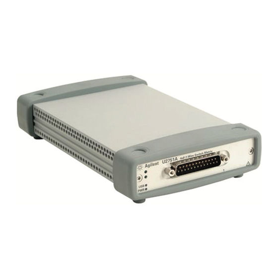
Getting Started Introduction The U2751A USB modular switch matrix offers a high quality, low cost switching solution for automated test. It can operate as a standalone or modular unit when used with the U2781A USB modular instrument chassis. The U2751A is a compact 4×8, two-wire modular switch matrix which is controlled remotely over a USB interface via the Agilent Measurement Manager software. -
Page 19: Product At A Glance
Getting Started Product at a Glance Product Outlook Top View Bumpers U2751A User’s and Service Guide... - Page 20 Getting Started Front View USB indicator Power indicator DSub connector Rear View 55-pin backplane connector USB inlet Fastening hole for USB cable with locking mechanism Power inlet U2751A User’s and Service Guide...
-
Page 21: Product Dimensions
Getting Started Product Dimensions Dimensions Without Bumpers Top View 105.00 mm 175.00 mm Front View 25.00 mm U2751A User’s and Service Guide... -
Page 22: Dimensions With Bumpers
Getting Started Dimensions With Bumpers Top View 117.00 mm 180.00 mm Front View 41.00 mm U2751A User’s and Service Guide... -
Page 23: Standard Shipped Items
Agilent Automation-Ready CD- ROM (contains the Agilent IO Libraries Suite) ✔ Agilent USB Modular Products and Systems Quick Start Guide ✔ Agilent USB Modular Products and Systems Product Reference DVD-ROM ✔ Agilent Measurement Manager Quick Reference Card U2751A User’s and Service Guide... -
Page 24: Inspection And Maintenance
Office immediately. The front of this manual contains the warranty information. Keep the original packaging in case the U2751A has to be returned to Agilent in the future. If you return the U2751A for service, attach a tag identifying the owner and model number. -
Page 25: Installation And Configuration
USB Modular Products and Systems Quick Start Guide to get started with the preparations and installation of your U2751A. You need to install the IVI-COM driver if you are going to use the U2751A N O T E ® ®... -
Page 26: U2751A Dsub Connector
Getting Started U2751A DSub Connector The U2751A is equipped with one 25-pin male DSub connector as shown in Figure 1- Figure 1-1 25-pin male DSub connector Pin Assignments Table 1-1 Pin assignments Description Description R represents “Row” and C represents “Column”. -
Page 27: U2922A Terminal Block
It allows the user to configure a wide variety of routing options and matrix topologies. The U2922A pin configuration is in accordance to the 25-pin male DSub connector of the U2751A as shown in the following: R represents “Row” and C represents “Column”. -
Page 28: Figure 1-3 U2922A Outlook
Getting Started The outlook and dimensions of the U2922A are shown in Figure 1- 3 Figure 1- Female DSub connector Jack screw Retractable cover Terminal block Figure 1-3 U2922A outlook U2751A User’s and Service Guide... -
Page 29: Figure 1-4 U2922A Dimensions
Getting Started Rear View 85.00 mm 23.00 mm Top View 90.00 mm 105.00 mm Front View Side View 85.00 mm 105.00 mm 23.00 mm 23.00 mm Figure 1-4 U2922A dimensions U2751A User’s and Service Guide... -
Page 30: U2922A Terminal Block Installation
This section provides the recommended procedure for connecting the U2922A terminal block to the U2751A. • The maximum working voltage of the U2751A with the WA R N I N G terminal block for standalone is 35 Vrms and for modular (when used with the U2781A) is 180 Vrms. - Page 31 Turn over the U2922A with the retractable cover facing downwards. Then, insert the U2922A to the U2751A as shown. Tighten the jack screws using a screw driver to secure the connection. Ensure that the terminal block is installed correctly with the screws properly tighten for secure operation.
-
Page 32: 55-Pin Backplane Connector Pin Configuration
Getting Started 55-Pin Backplane Connector Pin Configuration The 55-pin backplane connector is used when the U2751A module is inserted into the U2781A USB modular instrument chassis. For more details, refer to the Agilent U2781A USB Modular Instrument Chassis User's Guide. -
Page 33: Chassis Installation
Getting Started Chassis Installation The L-Mount kit is to be installed to your U2751A module. The following instructions describe the simple procedure of installing the L-Mount kit and your module in the U2781A chassis. 1 Unpack the L-Mount kit from its packaging. - Page 34 Getting Started THIS PAGE HAS BEEN INTENTIONALLY LEFT BLANK. U2751A User’s and Service Guide...
-
Page 35: Operation And Features
U2751A USB Modular Switch Matrix User’s and Service Guide Operation and Features Power Up Switch Control Relay Cycle Counter System-Related Operation Self-Test Error Conditions SCPI Commands for System-Related Tasks This chapter describes the features and operation of the U2751A. Agilent Technologies... -
Page 36: Power Up
Both of these are included when you purchase the U2751A. Refer to the Agilent USB Modular Products and Systems Quick Start Guide for the installation procedure. • On the front panel of the U2751A, there are two LED indicators. Refer to Chapter “Product Outlook”... -
Page 37: Switch Control
A matrix switch connects multiple inputs to multiple outputs. A matrix is arranged in rows and columns. For example, the U2751A is a 4×8 matrix that can be used to connect four sources to eight test points as shown in... -
Page 38: Figure 2-2 Panel View Of The Agilent Measurement Manager
Click the cross-point circles on the software to toggle the contact on or off. The connection from the row to the column will be highlighted when the circuit is closed. U2751A User’s and Service Guide... - Page 39 // Opens the relay at row 3, -> ROUTe:OPEN (@302) column 2. Example 3, Make contact at channel 101, 302 -> ROUTe:CLOSe (@101,302) // Closes relays at row 1, column 1 and row 3, column 2. U2751A User’s and Service Guide...
-
Page 40: Relay Cycle Counter
Relay cycles that are above a certain limit will be highlighted in red. Refer to the example in Figure 2- U2751A User’s and Service Guide... -
Page 41: System-Related Operation
Agilent Measurement Manager Operation Ensure that the switch terminals are not connected to any instrument. Turn on the U2751A. On the application panel, select Tools > Self-Test. This will perform a series of communication tests on the module, which take a couple of seconds to complete. -
Page 42: Scpi Commands For System-Related Tasks
// Returns a +0 if the test <- +0 pass else it will return a +1 if it fails. // Returns the error number -> SYST:ERR? and its corresponding message string from the error queue. <- +0, "No Error" U2751A User’s and Service Guide... -
Page 43: Characteristics And Specifications
U2751A USB Modular Switch Matrix User’s and Service Guide Characteristics and Specifications Product Characteristics Product Specifications This chapter specifies the characteristics, environmental conditions, and specifications of the U2751A. Agilent Technologies... -
Page 44: Product Characteristics
DIMENSIONS (W × D × H) • 105.00 × 175.00 × 25.00 mm (without bumpers) • 117.00 × 180.00 × 41.00 mm (with bumpers) WEIGHT • 428 g (without bumpers) • 480 g (with bumpers) U2751A User’s and Service Guide... - Page 45 Chapter 2 Compatible with Microsoft Windows operating systems only. 3 Requires a direct USB connection to the PC so the appropriate driver can be in- stalled in the USB modular instrument or USB DAQ module. U2751A User’s and Service Guide...
-
Page 46: Product Specifications
<3 dB <4.5 dB Capacitance HI-LO 55 pF 85 pF LO-Earth 35 pF 45 pF Crosstalk at terminal block (ch-ch) 300 kHz –70 dB 1 MHz –60 dB 20 MHz –35 dB 45 MHz –30 dB U2751A User’s and Service Guide... -
Page 47: Table 3-1. Electrical And Mechanical Specifications Update Per
1 DC or AC rms, channel-to-channel or channel-to-earth. 2 Limited to 6 W channel resistance power loss per module. 3 50 Ω source, 50 Ω load, differential measurements verified with a 4-port network analyzer (Sdd21). U2751A User’s and Service Guide... - Page 48 Characteristics and Specifications THIS PAGE HAS BEEN INTENTIONALLY LEFT BLANK. U2751A User’s and Service Guide...
-
Page 49: Service Information
U2751A USB Modular Switch Matrix User’s and Service Guide Service Information Checking Defective Relay(s) Replaceable Parts Disassembly Instructions Reassembly Instructions Contacting Agilent Technologies This chapter provides guidelines for returning your instrument to Agilent for service or repair, and for servicing it yourself. -
Page 50: Checking Defective Relay(S)
4 Now, open the particular relay(s). Using the same method, check if pins RxL and CyL are disconnected. Perform the same test on pins RxH and CyH as well. Row 1 Column 1 Figure 4-4 Defective relay(s) check U2751A User’s and Service Guide... -
Page 51: Replaceable Parts
• Minimize handling. • Keep the replacement parts in original static-free packaging. • Remove all plastics, styrofoams, vinyls, papers, and other static-generating materials from the immediate work area. • Use only antistatic solder extractor. U2751A User’s and Service Guide... -
Page 52: Disassembly Instructions
Service Information Disassembly Instructions Remove the screws and nuts as shown. Take the measurement board and carrier board out from the module. Remove the screws as indicated. U2751A User’s and Service Guide... - Page 53 Turn to the opposite side of the measurement board and ensure that only the defective relays are desoldered. Upon replacing the relay(s), reset the relay cycle count to zero by issuing the following SCPI command: DIAGnostic:RELay:CYCLes:CLEar (@<ch_list>) U2751A User’s and Service Guide...
-
Page 54: Reassembly Instructions
"Option 1." The defective unit must be returned to Agilent before the replacement unit N O T E is shipped to you. Additional information regarding the unit exchange will be provided when you contact Agilent. U2751A User’s and Service Guide... - Page 55 Internet Explorer. See browser panel view, DSub connector, 10, modular instrument chassis, 7, relay cycle count, 34, DUT, modular switch matrix. See introduction Agilent U2751A USB Modular Switch module driver. See installation Matrix, multiplexer, Quick Reference Card, electrical check, electrostatic discharge. See precautions...
- Page 56 2, pin configuration, relays, replacing terminal block, DIAGnostic:RELay:CLEar (@<ch_list>), USB extension cable, USB indicator, disassembly, USB interface, 2, ESD precautions, USBTMC 488.2, reassembly, replaceable parts. See parts, replaceable row, 2, 10, 21, 22, 23, VBUS, U2751A User’s and Service Guide...
- Page 57 Product specifications and descriptions in this document are subject to change without notice. Always refer to the English version on the Agilent Web site for the latest revision. ® Agilent Technologies, Inc. , 2008–2013 Fifth Edition, August 2, 2013 U2751-90011 Agilent Technologies...