Table of Contents
Advertisement
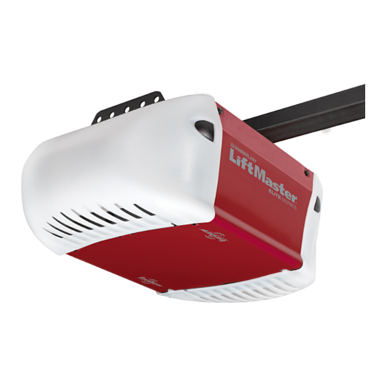
GARAGE DOOR OPENER
Model 3850
For Residential Use Only
Owner's Manual
■
Please read this manual and the enclosed safety materials carefully!
■
Fasten the manual near the garage door after installation.
The door WILL NOT CLOSE unless the Protector System
■
properly aligned.
■
Periodic checks of the opener are required to ensure safe operation.
■
The model number label is located under the light lens on the left side
panel of your opener.
®
The Chamberlain Group, Inc.
845 Larch Avenue
Elmhurst, Illinois 60126-1196
www.liftmaster.com
is connected and
®
Advertisement
Table of Contents

Related Manuals for Chamberlain LiftMaster Professional Security+ 3850


Summary of Contents for Chamberlain LiftMaster Professional Security+ 3850
- Page 1 Periodic checks of the opener are required to ensure safe operation. ■ The model number label is located under the light lens on the left side panel of your opener. ® The Chamberlain Group, Inc. 845 Larch Avenue Elmhurst, Illinois 60126-1196 www.liftmaster.com is connected and...
-
Page 2: Table Of Contents
Operation safety instructions .....26 Using your garage door opener ....26 Using the wall-mounted control console . -
Page 3: Preparing Your Garage Door
To prevent damage to garage door and opener: • ALWAYS disable locks before installing and operating the opener. • ONLY operate garage door opener at 120V, 60 Hz to avoid malfunction and damage. Tools needed During assembly, installation and adjustment of the opener, instructions will call for hand tools as illustrated below. -
Page 4: Planning
Planning Identify the type and height of your garage door. Survey your garage area to see if any of the conditions below apply to your installation. Additional materials may be required. You may find it helpful to refer back to this page and the accompanying illustrations as you proceed with the installation of your opener. -
Page 5: Carton Inventory
Carton Inventory Your garage door opener is packaged in two cartons which contain the motor unit and all parts illustrated below. Accessories will depend on the model purchased. Motion Detecting Control Console 2-Conductor Bell Wire White & White/Red Belt Pulley Bracket... -
Page 6: Assembly
ASSEMBLY STEP 1 Attach the Rail to the Motor Unit To avoid installation difficulties, do not run the garage door opener until instructed to do so. • Remove the two washered bolts mounted on top of motor unit. • Align rail and styrofoam over belt pulley. Cut tape from rail, chain and styrofoam. -
Page 7: Attach The Belt Cap Retainer
4. Disable ALL locks and remove ALL ropes connected to garage door BEFORE installing opener to avoid entanglement. 5. Install garage door opener 7 feet (2.1 m) or more above floor. 6. Mount emergency release handle 6 feet (1.8 m) above floor. -
Page 8: Determine The Header Bracket Location
INSTALLATION STEP 1 Determine the Header Bracket Location WARNING To prevent possible SERIOUS INJURY or DEATH: • Header bracket MUST be RIGIDLY fastened to structural CAUTION support on header wall or ceiling, otherwise garage door might not reverse when required. DO NOT install header bracket over drywall. -
Page 9: Install The Header Bracket
INSTALLATION STEP 2 Install the Header Bracket You can attach the header bracket either to the wall above the garage door, or to the ceiling. Follow the instructions which will work best for your particular requirements. Do not install the header bracket over drywall. -
Page 10: Attach The Rail To The Header Bracket
Header Wall Header Bracket Belt Pulley Bracket Garage Door HARDWARE SHOWN ACTUAL SIZE Clevis Pin 5/16"x2-3/4" INSTALLATION STEP 3 Attach the Rail to the Header Bracket • Position the opener on the garage floor below the header bracket. Use packing material as a protective base. -
Page 11: Position The Opener
• The top of the door should be level with the top of the motor unit. Do not position the opener more than 4" (10 cm) above this point. To prevent damage to garage door, rest garage door opener rail on 2x4 placed on top section of door. RELEASED... -
Page 12: Hang The Opener
INSTALLATION STEP 5 Hang the Opener Three representative installations are shown. Yours may be different. Hanging brackets should be angled (Figure 1) to provide rigid support. On finished ceilings (Figure 2 and Figure 3), attach a sturdy metal bracket to structural supports before installing the opener. -
Page 13: Install The Control Console
CAUTION INSTALLATION STEP 6 Install the Control Console Locate control console within sight of the door at a minimum height of 5 feet where small children cannot reach, and away from moving parts of the door and door hardware. The installation surface must be smooth and flat. -
Page 14: Install The Battery Backup (Optional)
• Reverse the procedure to close the lens. • If the bulbs burn out prematurely due to vibration, replace with a Garage Door Opener bulb. NOTE: Use only standard light bulbs. The use of short neck or speciality light bulbs may overheat the endpanel or light socket. -
Page 15: Attach The Emergency Release Rope And Handle
INSTALLATION STEP 9 Attach the Emergency Release Rope and Handle • Thread one end of the rope through the hole in the top of the red handle so “NOTICE” reads right side up as shown. Secure with an overhand knot at least 1"... -
Page 16: Install The Protector System (Safety Sensors)
6" (15 cm) max. above floor Facing the door from inside the garage ® Be sure power is NOT connected to the garage door opener BEFORE installing the safety reversing sensor. To prevent SERIOUS INJURY or DEATH from a closing garage door: •... - Page 17 INSTALLING THE BRACKETS Be sure power to the opener is disconnected. Install and align the brackets so the sensors will face each other across the garage door, with the beam no higher than 6" (15 cm) above the floor. They may be installed in one of three ways, as follows.
- Page 18 MOUNTING AND WIRING THE SAFETY REVERSING SENSORS • Slide a 1/4"-20x1/2" carriage bolt head into the slot on each sensor. Use wing nuts to fasten sensors to brackets, with lenses pointing toward each other across the door. Be sure the lens is not obstructed by a bracket extension (Figure 5).
-
Page 19: Fasten The Door Bracket
INSTALLATION STEP 12 Fasten the Door Bracket Follow instructions which apply to your door type as illustrated below or on the following page. A horizontal reinforcement brace should be long enough to be secured to two or three vertical supports. A vertical reinforcement brace should cover the height of the top panel. - Page 20 ONE-PIECE DOORS Please read and comply with the warnings and reinforcement instructions on the previous page. They apply to one-piece doors also. • Center the door bracket on the top of the door, in line with the header bracket as shown. Mark either the left and right, or the top and bottom holes.
-
Page 21: Connect Door Arm To Trolley
INSTALLATION STEP 13 Connect Door Arm to Trolley Follow instructions which apply to your door type as illustrated below and on the following page. SECTIONAL DOORS ONLY Make sure garage door is fully closed. Pull the emergency release handle to disconnect the outer trolley from the inner trolley. - Page 22 ALL ONE-PIECE DOORS 1. Assemble the Door Arm: • Fasten the straight and curved door arm sections together to the longest possible length (with a 2 or 3 hole overlap). • Make sure the garage door is fully closed. Connect the straight door arm section to the door bracket with the 5/16"x1-1/4"...
-
Page 23: Adjustment
ADJUSTMENT STEP 1 Program the Travel Limits Travel limits regulate the points at which the door will stop when moving up or down. Follow the steps below to set the limits. Figure 1 To program the travel limits: Adjust the position of the door by using the black and purple buttons. -
Page 24: Setting The Force
ADJUSTMENT STEP 2 Setting the Force The force setting button is located on the left panel of the motor unit. The force setting measures the amount of force required to open and close the door. 1. Locate the purple button on the left panel of the motor unit (Figure 1). -
Page 25: Test The Safety Reversal System
The door will not move more than an inch (2.5 cm), and the opener lights will flash. The garage door opener will not close from a remote if the indicator light in either sensor is off (alerting you to the fact that the sensor is misaligned or obstructed). -
Page 26: Operation
• The wall-mounted control console: Hold the push button or bar down until the door starts to move. • The Keyless Entry (See Accessories): If provided with your garage door opener, it must be programmed before use. See Programming. When the opener is activated (with the safety reversing sensor correctly installed and aligned) 1. -
Page 27: Using The Wall-Mounted Control Console
Using the Wall-Mounted Door Control THE MOTION DETECTING CONTROL CONSOLE Press the push bar to open or close the door. Press again to reverse the door during the closing cycle or to stop the door while it’s opening. This door control contains a motion detector that will automatically turn on the light when it detects a person... -
Page 28: Battery Backup (Optional)
Battery Backup (Optional) WARNING OPERATING INSTRUCTIONS 1. Test the installed battery with the motor unit. CAUTION To test the battery, disconnect the motor unit power cord from the electrical outlet. • A solid orange LED indicates the battery is operating on battery power. -
Page 29: Care Of Your Garage Door Opener
Care of Your Opener MAINTENANCE SCHEDULE Once a Month • Manually operate door. If it is unbalanced or binding, call a trained door systems technician. • Check to be sure door opens & closes fully. Adjust limits and/or force if necessary. (See pages 23 and 24.) •... -
Page 30: Having A Problem (Troubleshooting)
Limits. Decrease down travel. 5. My lights will not turn off when door is open: • The garage door opener is equipped with a security light feature. This feature activates the light on when the safety reversing sensor beam has been obstructed. -
Page 31: Diagnostic Chart
5 FLASHES Possible RPM sensor failure. Unplug to reset. Your garage door opener is programmed with self-diagnostic capabilities. The “Learn” button/diagnostic LED will flash a number of times then pause signifying it has found a potential issue. Consult Diagnostic Chart below. -
Page 32: Programming
The owner of the copyright in the garage door opener does not authorize the purchaser or supplier of the non-rolling code remote control to circumvent that technical measure. -
Page 33: To Add, Reprogram Or Change A Keyless Entry Pin
To Add, Reprogram or Change a Keyless Entry PIN NOTE: Your new Keyless Entry must be programmed to operate your garage door opener. USING THE “LEARN” BUTTON 1. Press and release the “learn” button on motor unit. The learn indicator light will glow steadily for 30 seconds. -
Page 34: Repair Parts
REPAIR PARTS Rail Assembly Parts Installation Parts KEY PART 98LM 373LM 10A20 29B137 41A2828 41B4494-1 41A5047-1 41A4353-1 41A5034 178B34 178B35 41A5266-1 485LM 41A2770-5 114A3281 114A3281SP Owner’s manual - Spanish PART DESCRIPTION 4A1008 Master link kit 41B5424 Belt pulley bracket 41B3869-1 Complete trolley assembly 109B33 Trolley clip... -
Page 35: Motor Unit Assembly Parts
Motor Unit Assembly Parts PART DESCRIPTION 41C76 Belt cap and sprocket 41B4245 Line cord 41B4375-3 Terminal block with screws 41A6281 Wire harness kit Complete with: 41A6282 Battery wires and plug 41A6327 Light socket wires and plug 41A6328 RPM/passpoint wires with plug 41D794 Motor with positioning sensor 41DB002-2... -
Page 36: Accessories
Push bar, light feature and auxiliary button. Includes battery. 485LM Battery Backup System: Provides backup power to the garage door opener. For use with model 3850 only. 975LM Laser Park Assist: Laser enables homeowners to precisely park vehicles in the garage. 990LM... -
Page 37: Notes
NOTES... -
Page 40: Repair Parts And Service
The Chamberlain Group, Inc. (“Seller”) warrants to the first retail purchaser of this product, for the residence in which this product is originally installed, that it is free from defect in materials and/or workmanship for a period of 60 full months from the date of purchase [and that the motor and belt] are free from defect in materials and/or workmanship for a period of the lifetime of the product].