Table of Contents
Advertisement
Available languages
Available languages
Quick Links
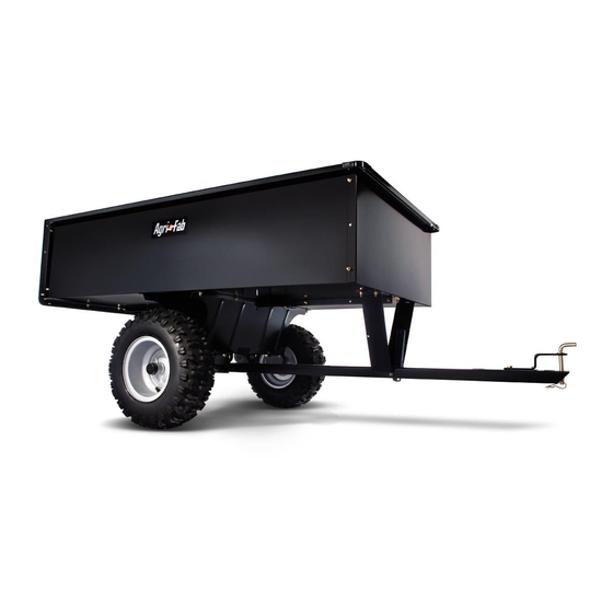
OWNERS MANUAL
MANUAL DEL USUARIO
NOTICE D'UTILISATION
Model No.
Modelo No.
Modèle No.
45-02402 ATV
Read Rules for
Safe Operation
and Instructions
PRECAUCION:
Lea cuidadosamente
los Procedimientos e
Instrucciones para la
Operación Segura de la
ATTENTION:
Lire et suivre attentivement
les instructions et
consignes de sécurité de
cette notice.
PRINTED IN USA
™
CAUTION:
• Assembly
Carefully
• Safety
• Operation
• Maintenance
• Parts
Máquina.
the fastest way to purchase parts www.speedepart.com
UTILITY ATV CART
CARRITOS
REMORQUE UTILITAIRE
• Montaje
• Seguridad
• Operación
• Mantenimiento
• Piezas de Repuesto
Call 1-800-448-9282 for missing parts or assembly help.
• Assemblage
• Sécurité
• Utilisation
• Entretien
• Pièces de Rechange
FORM NO. 42372 (12/21/11)
Advertisement
Table of Contents

Related Manuals for Agri-Fab 45-02402 ATV


Summary of Contents for Agri-Fab 45-02402 ATV
- Page 1 ™ OWNERS MANUAL MANUAL DEL USUARIO NOTICE D’UTILISATION Model No. Modelo No. Modèle No. 45-02402 ATV UTILITY ATV CART CARRITOS REMORQUE UTILITAIRE CAUTION: Read Rules for Safe Operation and Instructions • Assembly Carefully • Safety • Operation PRECAUCION: • Maintenance Lea cuidadosamente • Parts...
-
Page 2: Safety Rules
ENGLISH SAFETY RULES Remember, any power equipment can cause injury if operated improperly or if the user does not understand how to operate the equipment. Exercise caution at all times when using power equipment. CAUTION: VEHICLE BRAKING AND LOOK FOR THIS SYMBOL TO POINT OUT STABILITY MAY BE AFFECTED WITH THE IMPORTANT SAFETY PRECAUTIONS. IT ADDITION OF AN ACCESSORY OR AN MEANS – ATTENTION! BECOME ALERT! ATTACHMENT. BE AWARE OF CHANGING YOUR SAFETY IS INVOLVED. - Page 3 ENGLISH HARDWARE SHOWN FULL SIZE 47810 47189 46980 43012 43814 HA21362 43001 47407 Not Shown Full Size 43014 47622 43343 23353 43093 43601 45132 47407 FIGURE 1 - HARDWARE PACK REF. QTY. DESCRIPTION Hex Bolt, 5/16-18 x 4" Hex Bolt, 1/4" x 3/4" Hex Bolt, 3/8" x 1" Truss Hd. Bolt, 5/16" x 3/4" Nylock Nut, 1/4" SEMS Nut, 5/16" Nylock Nut, 5/16" Nylock Nut, 3/8"...
- Page 4 ENGLISH ASSEMBLY INSTRUCTIONS 5. Position the tailgate reinforcement bracket on outside of cart as shown in figure 3. Assemble to the bottom of the cart body using four 5/16" x 3/4" truss head bolts and TOOLS REQUIRED FOR ASSEMBLY 5/16" nylock nuts. Do not tighten yet. See figure 3. (1) Screwdriver 6. Position the tailgate guides on the inside of the cart bodies Pliers with guide channels to the front as shown in figure 3. (2) 7/16" Wrenches Assemble using four 1/4" x 3/4" hex bolts and 1/4" nylock nuts. Do not tighten yet. See figure 3. (2) 1/2" Wrench (2) 9/16" Wrenches 1/4" NYLOCK NUT Grease Gun TAILGATE GUIDE 1/4"...
- Page 5 ENGLISH 9. Assemble the front panel over the end of the cart using 11. Turn the latch stand bracket so that the aligning tab is six 1/4" x 3/4" hex bolts and 1/4" nylock nuts as shown at the rear (bottom) of the bracket. Assemble the latch in figure 5. Leave two holes in the bottom of the panel stand bracket to the cart using four 1/4" x 3/4" hex bolts empty as shown. With the cart body halves pulled and 1/4" nylock nuts. TIGHTEN. See figure 7. together, tighten the bolts in the bottom of the front panel, then tighten the bolts in the sides. See figure LATCH STAND BRACKET 1/4" x 3/4" At this time tighten the bolts assembled in step 4, which HEX BOLT fasten the bottom of the cart together. LEAVE HOLES OPEN FOR 1/4"...
- Page 6 ENGLISH 13. To prevent accidental tipping during the following 16. Hook the short end of the spring into the hole in the assembly procedures, lower the cart to rest upside down latch lock lever. Use the spring puller tool to hook the on its top flanges, so that the wheel support is facing long end of the spring into the square hole in the tongue. up. See figure 9. The spring puller tool can be stored when finished. See 14. Lay the drawbar tongue (open side facing up) onto the figure 11. Wheel Support and the Latch Stand Bracket. Assemble the axle through the wheel support and the tongue. See figure 9. SPRING PULLER TOOL AXLE DRAW BAR TONGUE LONG END OF SPRING LATCH STAND BRACKET LATCH LOCK LEVER FIGURE 9 FIGURE 11 17. Assemble a spacer, a flat washer, a wheel with the valve...
-
Page 7: Operation
ENGLISH OPERATION IMPORTANT: Make sure drawbar tongue is securely locked to the latch stand bracket by the latch lock lever. 19. Turn cart over so that it rests right side up on its wheels. CAUTION: VEHICLE BRAKING AND 20. Assemble the end of the hitch bracket (two holes) down STABILITY MAY BE AFFECTED WITH THE through the slot at the front of the drawbar tongue. ADDITION OF AN ACCESSORY OR AN Fasten it to the tongue using the 3/8" x 1" hex bolt, and ATTACHMENT. BE AWARE OF CHANGING 3/8" nylock nut. Tighten. See figure 13. -
Page 8: Slope Guide
ENGLISH SLOPE GUIDE (Keep this sheet in a safe place for future reference.) Use this guide to determine if a slope is safe for the operation of your tractor and cart. Refer also to the instructions in your vehicle owners manual. -
Page 10: Instructions De Montage
FRANÇAIS SÉCURITÉ Tout appareil mécanique utilisé incorrectement peut être la cause de blessures. L’utilisateur doit bien en maîtriser le fonctionnement. Observez en tout temps la plus grande prudence lorsque vous utilisez un appareil mécanique. ATTENTION: LA STABILITÉ ET LA CAPACITÉ CE SYMBOLE ATTIRE L’ATTENTION SUR DES DE FREINAGE D’UN VÉHICULE PEUT ÊTRE MESURES DE SÉCURITÉ IMPORTANTES. DIMINUÉE PAR L’AJOUT D’UN ACCESSOIRE. IL SIGNIFIE: «ATTENTION, DEMEUREZ SOYEZ VIGILANT DANS LES PENTES. VIGILANT, VOTRE SÉCURITÉ EN DÉPEND.» 1. Lisez attentivement ce manuel avant d’assembler et d’utiliser la remorque. 2. Lisez le manuel d’utilisation du tracteur afin d’en bien maîtriser le fonctionnement avant d’y attacher la remorque. 3. Ne jamais transporter de passagers dans la remorque puisqu’elle n’a pas été conçue à cet effet. 4. Les enfants ne devraient jamais être autorisés à utiliser le tracteur et la remorque. 5. Les adultes qui n’ont pas reçu d’instructions précises préalablement ne devraient pas utiliser ces appareils. 6. Démarrez toujours l’appareil à la plus basse vitesse, puis augmentez graduellement si les conditions de terrain le permettent. 7. Tirez la remorque à vitesse réduite en terrains accidentés ou à flanc de coteau, près des fossés et des cours d’eau, afin d’éviter de basculer ou de perdre le contrôle. Évitez de conduire près des fossés et des cours d’eau. 8. Le freinage et la stabilité du véhicule peuvent être affectés par l’attache de cette remorque. Ne pas remplir la remorque à capacité maximale sans vérifier la tolérance du véhicule remorqueur à tirer et à s’arrêter avec cet accessoire. 9. Avant d’utiliser le véhicule, référez-vous aux règles de sécurité de votre manuel de l’utilisateur, particulièrement en ce qui a trait à la conduite en pentes. Consultez également le guide de ce manuel à la page 13. Évitez les pentes abruptes! 10. Ne pas utiliser cette remorque sur la voie publique. - Page 11 FRANÇAIS 9. Assemblez le panneau avant sur l’extrémité de la remorque 17. Montez une entretoise, une rondelle plate, une roue avec la tige de soupape faisant face vers l'extérieur, une autre en utilisant six boulons hex. 1/4” x 3/4” et des contre-écrous rondelle plate sur l'essieu comme montré dans la figure 12. hex 1/4” comme montré dans la figure 5. Laissez deux Fixez solidement la roue sur l'essieu au moyen d'une goupille, trous vides en bas du panneau comme indiqué. Ayant les en écartant ses extrémités. Montez le chapeau de moyeu en éléments de moitié de carrosserie lies l’un à l’autre, serrez l'appuyant par une pression sur la rondelle plate. Répétez la les boulons en bas du panneau avant, puis serrez les manœuvre sur l'autre extrémité de l'essieu. boulons sur les côtés. Voir figure 5. A ce stade, serrez les boulons assemblés lors de l’étape 4, ce qui fixe le bas de la 18. Graissez les roues à l’aide d’un pistolet graisseur. remorque avec celle-ci. IMPORTANT: Pompez la graisse dans les raccords de graissage 10. Assemblez le support de roue à la remorque en utilisant 8 jusqu’à ce qu’elle sorte au niveau des moyeux des roues.
-
Page 12: Entretien
FRANÇAIS UTILISATION ENTRETIEN 1. Au commencement de chaque saison, graissez au moyen d'une machine à graisser légère, le verrou, le boulon pivot du ATTENTION: LA STABILITÉ ET LA CAPACITÉ verrou, et la zone de l'essieu où la barre de traction d'attelage DE FREINAGE D’UN VÉHICULE PEUT ÊTRE pivote. DIMINUÉE PAR L’AJOUT D’UN ACCESSOIRE. SOYEZ VIGILANT DANS LES PENTES. 2. Graissez ou lubrifiez les roulements des roues périodiquement. Utilisez de la graisse pour roulement de roue d'automobile ou de l'huile de poids 20. Se référer au manuel du tracteur pour des instructions précises concernant la conduite en pentes. - Page 13 FRANÇAIS GUIDE DE CALCUL D’UNE PENTE (Conservez cette feuille en lieu sûr pour référence future.) Utilisez ce guide afin de déterminer si une pente est sécuritaire pour l’utilisation de votre tracteur et de la remorque. Voir également les instructions incluses dans votre manuel d’utilisation du tracteur.
-
Page 14: Reglas De Seguridad
ESPAÑOL REGLAS DE SEGURIDAD Cualquier equipo movido por motor puede causar lesiones si se opera inadecuadamente o si el usuario no entiende cómo debe operarlo. Manténgase atento y cauteloso siempre que opere el equipo. PRECAUCION: LA ESTABILIDAD DEL ESTE SIMBOLO INDICA PRECAUCIONES VEHICULO Y SU CAPACIDAD DE FRENADO IMPORTANTES DE SEGURIDAD. SIGNIFICA PUEDEN AFECTARSE AL REMOLCAR UN — ¡ATENCION! SU SEGURIDAD ESTA EN ACCESORIO O UN VEHICULO ADICIONAL. - Page 15 ESPAÑOL 7. En este momento, con las dos mitades del cuerpo del car- 16. Coloque el extremo corto del muelle en el orificio de la palanca rito juntas, apriete los cuatro tornillos con cabeza reforzada de bloqueo del cierre. Utilice un extractor de muelles, tal y colocados en el paso 5 y, a continuación, los cuatro tornillos como se muestra en la figura 11, para acoplar el extremo con cabeza hex. colocados en el paso 6. De momento, deje largo del muelle en el orificio cuadrado de la lengüeta. flojos los tornillos colocados en el paso 4. 17. Coloque un expaciador, una arandela plana, un rueda con 8. Con mucho cuidado, invierta la posición del carrito, de modo la válvula del neumático mirando hacia fuera y una arandela que descanse sobre el extremo con el soporte de refuerzo de plana en el eje, tal y como se muestra en la figura 12. Fije la puerta trasera recién montado, tal y como se muestra en la rueda al eje con un pasador de aletas, desplegando los la figura 4. Prosiga con los pasos de montaje que se indican extremos. Coloque la tapa del cubo presionándola sobre la a continuación. arandela plana. Repita la operación en el otro extremo del eje. 9. Monte el panel delantero sobre el extremo del carrito utilizando seis tornillos con cabeza hex. 1/4"x 3/4" ytuercas de bloqueo 18.
-
Page 16: Mantenimiento
ESPAÑOL MANTENIMIENTO OPERACIÒN 1. Con cada cambio de estación, utilice aceite ligero para máquinas para lubricar el cierre, el tornillo de giro del cierre PRECAUCIÓN: LA CAPACIDAD DE FRENADO y la zona del eje en la que gira la lengüeta de enganche. Y LA ESTABILIDAD DEL VEHÍCULO PUEDEN VERSE AFECTADAS POR LA UTILIZACIÓN DE 2. Engrase o lubrique con aceite los cojinetes de las ruedas de CUALQUIER TIPO DE ACCESORIO. TENGA EN forma periódica. Utilice aceite de automoción para cojinetes CUANTA LAS CONDICIONES CAMBIANTES de ruedas o aceite 20W. - Page 17 ESPAÑOL GUIA DE PENDIENTES (Mantenga esta guía en un lugar seguro para referencia futura.) Use esta guía para determinar si la operación de tractor y carrito es segura en una pendiente. Consulte también las instrucciones en el Manual del Usuario de su vehículo.
- Page 18 REPAIR PARTS FOR UTILITY CART MODEL NO. 45-02402-ATV...
- Page 19 REPAIR PARTS LIST FOR UTILITY CART MODEL NO. 45-02402-ATV REF. PART QTY. DESCRIPTION 24096 Cart Body 23504 Tailgate 62457 Tailgate Reinforcement Bracket 23548 Tailgate Guide 23490 Front Panel 23487 Wheel Support 24497 Latch Stand Bracket 24498 Latch Lock Lever 23014 Hitch Bracket 24750 Draw Bar Tongue 27336 Axle, 1" Dia. 23484 Front Corner Cap 40758 Wheel 43093...
- Page 20 REPAIR PARTS Agri-Fab, Inc. 303 West Raymond Sullivan, IL. 61951 217-728-8388 www.agri-fab.com This document (or manual) is protected under the U.S. Copyright Laws and the copyright laws of foreign countries, pursuant to the Universal Copyright Convention and the Berne convention. No part of this document may be reproduced or transmitted in any form or by any means, electronic or mechanical, including photocopying or recording, or by any information storage or retrieval system, without the express written permission of Agri-Fab, Inc. Unauthorized uses and/or reproductions of this manual will subject such unauthorized user to civil and criminal penalties as provided by the United States Copyright Laws. © 2002 Agri-Fab, Inc.