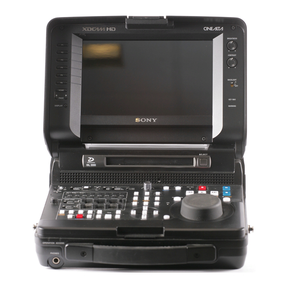
Sony PDWHR1 Installation Manual
Sxs memory card adaptor
Hide thumbs
Also See for PDWHR1:
- Operation manual (214 pages) ,
- Operations & installation manual (60 pages) ,
- Brochure (4 pages)
Advertisement
Available languages
Available languages
Quick Links
Advertisement

Summary of Contents for Sony PDWHR1
- Page 1 SxS MEMORY CARD ADAPTOR PDBK-MK1 INSTALLATION MANUAL 1st Edition...
- Page 2 ! 警告 このマニュアルは,サービス専用です。 お客様が,このマニュアルに記載された設置や保守,点検,修理などを行うと感電や火災, 人身事故につながることがあります。 危険をさけるため,サービストレーニングを受けた技術者のみご使用ください。 設置や保守,点検,修理などを行う前に,PDW-HR1 に付属している下記マニュアルの「安全 のために」を必ずお読みください。 . インストレーションマニュアルおよびオペレーションマニュアル ! WARNING This manual is intended for qualified service personnel only. To reduce the risk of electric shock, fire or injury, do not perform any servicing other than that contained in the operating instructions unless you are qualified to do so. Refer all servicing to qualified service personnel.
- Page 3 第 1 章 設置 1-2. 設置のための一般情報 本書の目的 本書は,SxS メモリーカードアダプター PDBK-MK1 のイン 部品構成 ストレーションマニュアルです。 本書は,システム/サービスエンジニアの方々にご使用い 本機は以下の部品で構成されています。 ただくことを想定し, PDBK-MK1 の納入設置時に必要な情 . MK1 組立 報を記載しています。 . スロットカバー SUB 組立 . 同軸ケーブル . ハーネス (IF-DPR) 関連マニュアル . ハーネスカバー PDBK-MK1 には,この「インストレーションマニュアル」 . ハーネスクランプ (2 個 ) の他に,下記のマニュアルが用意されています。 . インストレーションマニュアル...
- Page 4 1-3. 設置手順 5. ネジ 2 本を外す。 6. 図に示すようにマイナスドライバー(小)2 本の先端 を 切 り 欠 き 部 に 挿 入 し, 矢 印 方 向 に 回 転 さ せ て 1. ネジ 8 本を外し,リアパネル組立を矢印方向に取り外 NET-5 基板を引き出す。 す。 7. NET-5 基板を矢印 方向に取り外す。 ...
- Page 5 8. 本体を裏返してネジ 6 本を外し,ボトムパネル組立を 10. VPR-15 基板のナイロンリベット 1 個を取り外し,付 取り外す。 属のハーネスクランプを取り付ける。 11. 付 属 の 同 軸 ケ ー ブ ル を VPR-15 基 板 の コ ネ ク タ ー ボトムパネル組立を外す際は,EM-8 基板にマウント CN202, CN203, CN204 に接続し,ハーネスクランプ されている IC の破損に注意してください。 に通す。 12. NET-5 基板のナイロンリベット 1 個を取り外し,付属 9. VPR-15 基板に...
- Page 6 14. 手順 9 で TSI-60A 基板を取り外した場合は,逆の手順 17. ハーネス (IF-DPR) を図に示す位置から引き出しながら, で取り付ける。 NET-5 基板をスロットに挿入する。 TSI-60A 基板非装着の場合には, 付属のネジ 4 本でハー 18. NET-5 基板のコネクターが,MB-1138 基板のコネク ネスカバーを取り付ける。 ターに確実に接続するまでスロットに押し込み,ネジ 2 本で締め付ける。 15. 同軸ケーブルを図に示す位置から引き出しながら, 19. DPR-321 基 板 (MK1 組 立 ) の コ ネ ク タ ー CN3400 を VPR-15 基板をスロットに挿入する。...
- Page 7 21. VPR-15 基板に接続した同軸ケーブルと NET-5 基板に 23. PDW-HR1 のボトムパネル組立からネジ 2 本を外し, 接続したハーネスを DPR-321 基板のコネクターに接続 スロットカバーを取り外す。 し,図のように引き回す。 24. PDW-HR1 にボトムパネル組立を取り付ける。 (手順 8 参照) 22. ハーネスと同軸ケーブルの余り分をまとめてシャー シーの内側へ押し込み,ケーブルカバーを取り付ける。 25. 付属のネジ 2 本でスロットカバー SUB 組立を取り付け る。 スロットカバー SUB 組立はボトムパネル組立の A 部に 押し当ててからネジを締めてください。 26. PDW-HR1 にリアパネル組立を取り付ける。 (手順...
- Page 8 1-4. 設置後の設定 確認手順 1. [HOME] ボ タ ン と [SHIFT] ボ タ ン を 押 し な が ら, [MENU] ボタンを押す。 メンテナンスメニューが表示される。 MAINTENANCE MENU M0:CHECK M1:ADJUST M2:SERVICE SUPPORT M3:OTHERS M4:SETUP MAINTENANCE M5:NETWORK M6:DRIVE 2. [PUSH|SET] つまみを回して M2 : SERVICE SUPPORT を選択し,[PUSH|SET] つまみを押す。 3. [PUSH|SET] つまみを回して M22 : OPTION STATUS を選択し,[PUSH|SET] つまみを押す。...
-
Page 9: Section 1 Installation
. Operation Manual . CD-ROM tion and repair information required for parts-level . Attaching screws service. For obtaining, contact your local Sony Sales Office/ +B3 x 6 (2) +PSW2.6 x 6 (8) Service Center. +B2.6 x 3 (4) 1-1. Specifications... -
Page 10: Installation Procedure
1-3. Installation Procedure 5. Remove the two screws. 6. Insert the ends of two flat-blade screwdrivers (small) into the cutout portions as shown in the figure, and turn 1. Remove the eight screws and remove the rear panel them in the arrow A direction to draw out the NET-5 assembly in the arrow direction. - Page 11 8. Turn the unit upside down, remove the six screws, and 10. Remove the nylon rivet from the VPR-15 board, and then remove the bottom panel assembly. install the supplied harness clamp instead. 11. Connect the supplied coaxial cable to the connectors After the bottom panel assembly is removed, be care- CN202, CN203, and CN204 on the VPR-15 board, and ful not to damage the IC on the EM-8 board.
- Page 12 14. When the TSI-60A board was removed in step 9, 17. While pulling out the harness (IF-DPR) from the install it by reversing the steps of removal. location shown in the figure, insert the NET-5 board When the TSI-60A board is not mounted, attach the into the slot. harness cover with the supplied four screws. 18. Push the NET-5 board into the slot until its connectors are firmly connected to the MB-1138 board connectors, and then secure the NET-5 board with two screws.
- Page 13 21. Connect the coaxial cable (connected to the VPR-15 23. Remove the two screws from the bottom panel assem- board) and the harness (connected to the NET-5 board) bly of the PDW-HR1 to detach the slot cover. to the connectors on the DPR-321 board, and arrange them as shown in the figure.
-
Page 14: Settings After Installation
1-4. Settings after Installation Check procedure 1. While press the [HOME] button and the [SHIFT] button simultaneously, press the [MENU] button. The MAINTENANCE MENU is displayed. MAINTENANCE MENU M0:CHECK M1:ADJUST M2:SERVICE SUPPORT M3:OTHERS M4:SETUP MAINTENANCE M5:NETWORK M6:DRIVE 2. Rotate the [PUSH|SET] knob to select M2: SERVICE SUPPORT, and press the [PUSH|SET] knob. - Page 15 (操作,保守等) と異なる目的で本マニュアルを使用する ことを禁止します。 The material contained in this manual consists of information that is the property of Sony Corporation. Sony Corporation expressly prohibits the duplication of any portion of this manual or the use thereof for any purpose other than the operation or maintenance of the equipment described in this manual without the express written permission of Sony Corporation.
- Page 16 Printed in Japan Sony Corporation PDBK-MK1 (SY) J,E 2010. 7 08 4-195-333-01 (1) ©2010...


